2002 JEEP LIBERTY service
[x] Cancel search: servicePage 17 of 1803

FLUID FILL/CHECK
LOCATIONS
DESCRIPTION
The fluid check/fill point locations are located in
each applicable service manual section.
MAINTENANCE SCHEDULES
DESCRIPTION
9Maintenance Schedule Information not included in
this section, is located in the appropriate Owner's
Manual.9
HOISTING
STANDARD PROCEDURE - HOISTING
RECOMMENDATIONS
Refer to the Owner's Manual for emergency vehicle
lifting procedures.
When properly positioned, a floor jack can be used
to lift a Jeep vehicle (Fig. 4). Support the vehicle in
the raised position with jack stands at the front and
rear ends of the frame rails.CAUTION: Do not attempt to lift a Jeep vehicle with
a floor jack positioned under:
²A body side sill.
²A steering linkage component.
²A drive shaft.
²The engine or transmission oil pan.
²The fuel tank.
²A front suspension arm.
²Transfer case.
NOTE: Use the correct sub-frame rail or frame rail
lifting locations only.
HOIST
Refer to the Owner's Manual for emergency vehicle
lifting procedures.
A vehicle can be lifted with:
²A single-post, frame-contact hoist.
²A twin-post, chassis hoist.
²A ramp-type, drive-on hoist.
NOTE: When a frame-contact type hoist is used,
verify that the lifting pads are positioned properly.
WARNING: THE HOISTING AND JACK LIFTING
POINTS PROVIDED ARE FOR A COMPLETE VEHI-
CLE. WHEN A CHASSIS OR DRIVETRAIN COMPO-
NENT IS REMOVED FROM A VEHICLE, THE
CENTER OF GRAVITY IS ALTERED MAKING SOME
HOISTING CONDITIONS UNSTABLE. PROPERLY
SUPPORT OR SECURE VEHICLE TO HOISTING
DEVICE WHEN THESE CONDITIONS EXIST.
Fig. 4 Correct Vehicle Lifting Locations
1 - Frame Contact Lift (Single Post)
Chassis Lift (Non-Axle Dual Post)
Outboard Lift (Dual Post)
Floor Jack
2 - Floor Jack
KJLUBRICATION & MAINTENANCE 0 - 5
Page 33 of 1803

SPRING
REMOVAL
(1) Raise and support the vehicle.
(2) Remove the tire and wheel assembly.
(3) Remove the shock. Refer to the proper side
shock removal procedure being worked on. (Refer to 2
- SUSPENSION/FRONT/SHOCK - REMOVAL).
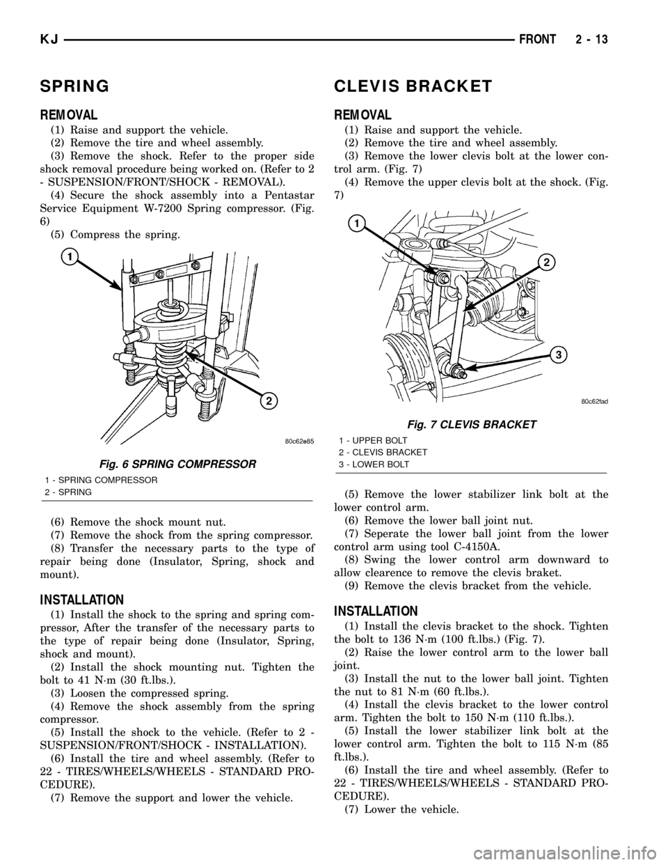
(4) Secure the shock assembly into a Pentastar
Service Equipment W-7200 Spring compressor. (Fig.
6)
(5) Compress the spring.
(6) Remove the shock mount nut.
(7) Remove the shock from the spring compressor.
(8) Transfer the necessary parts to the type of
repair being done (Insulator, Spring, shock and
mount).
INSTALLATION
(1) Install the shock to the spring and spring com-
pressor, After the transfer of the necessary parts to
the type of repair being done (Insulator, Spring,
shock and mount).
(2) Install the shock mounting nut. Tighten the
bolt to 41 N´m (30 ft.lbs.).
(3) Loosen the compressed spring.
(4) Remove the shock assembly from the spring
compressor.
(5) Install the shock to the vehicle. (Refer to 2 -
SUSPENSION/FRONT/SHOCK - INSTALLATION).
(6) Install the tire and wheel assembly. (Refer to
22 - TIRES/WHEELS/WHEELS - STANDARD PRO-
CEDURE).
(7) Remove the support and lower the vehicle.
CLEVIS BRACKET
REMOVAL
(1) Raise and support the vehicle.
(2) Remove the tire and wheel assembly.
(3) Remove the lower clevis bolt at the lower con-
trol arm. (Fig. 7)
(4) Remove the upper clevis bolt at the shock. (Fig.
7)
(5) Remove the lower stabilizer link bolt at the
lower control arm.
(6) Remove the lower ball joint nut.
(7) Seperate the lower ball joint from the lower
control arm using tool C-4150A.
(8) Swing the lower control arm downward to
allow clearence to remove the clevis braket.
(9) Remove the clevis bracket from the vehicle.
INSTALLATION
(1) Install the clevis bracket to the shock. Tighten
the bolt to 136 N´m (100 ft.lbs.) (Fig. 7).
(2) Raise the lower control arm to the lower ball
joint.
(3) Install the nut to the lower ball joint. Tighten
the nut to 81 N´m (60 ft.lbs.).
(4) Install the clevis bracket to the lower control
arm. Tighten the bolt to 150 N´m (110 ft.lbs.).
(5) Install the lower stabilizer link bolt at the
lower control arm. Tighten the bolt to 115 N´m (85
ft.lbs.).
(6) Install the tire and wheel assembly. (Refer to
22 - TIRES/WHEELS/WHEELS - STANDARD PRO-
CEDURE).
(7) Lower the vehicle.
Fig. 6 SPRING COMPRESSOR
1 - SPRING COMPRESSOR
2 - SPRING
Fig. 7 CLEVIS BRACKET
1 - UPPER BOLT
2 - CLEVIS BRACKET
3 - LOWER BOLT
KJFRONT 2 - 13
Page 57 of 1803

SINGLE CARDAN UNIVERSAL
JOINTS
DISASSEMBLY
NOTE: Individual components of cardan universal
joints are not serviceable. If worn or leaking, they
must be replaced as an assembly.
(1) Remove the propeller shaft.
(2) Tap the outside of the bearing cap assembly
with a drift to loosen snap ring.
(3) Remove snap rings from both sides of yoke
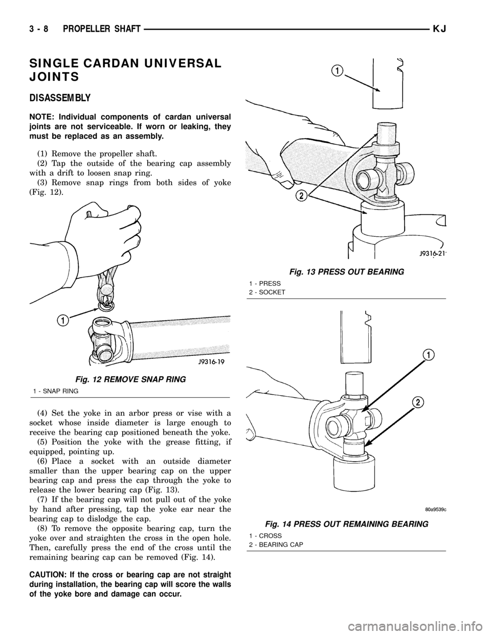
(Fig. 12).
(4) Set the yoke in an arbor press or vise with a
socket whose inside diameter is large enough to
receive the bearing cap positioned beneath the yoke.
(5) Position the yoke with the grease fitting, if
equipped, pointing up.
(6) Place a socket with an outside diameter
smaller than the upper bearing cap on the upper
bearing cap and press the cap through the yoke to
release the lower bearing cap (Fig. 13).
(7) If the bearing cap will not pull out of the yoke
by hand after pressing, tap the yoke ear near the
bearing cap to dislodge the cap.
(8) To remove the opposite bearing cap, turn the
yoke over and straighten the cross in the open hole.
Then, carefully press the end of the cross until the
remaining bearing cap can be removed (Fig. 14).
CAUTION: If the cross or bearing cap are not straight
during installation, the bearing cap will score the walls
of the yoke bore and damage can occur.
Fig. 12 REMOVE SNAP RING
1 - SNAP RING
Fig. 13 PRESS OUT BEARING
1 - PRESS
2 - SOCKET
Fig. 14 PRESS OUT REMAINING BEARING
1 - CROSS
2 - BEARING CAP
3 - 8 PROPELLER SHAFTKJ
Page 59 of 1803

HALF SHAFT
TABLE OF CONTENTS
page page
HALF SHAFT
CAUTION.............................10
DIAGNOSIS AND TESTING - HALF SHAFT....10
REMOVAL.............................10
INSTALLATION.........................11
SPECIFICATIONS
HALF SHAFT.........................11SPECIAL TOOLS.......................12
CV JOINT/BOOT-OUTER
REMOVAL.............................12
INSTALLATION.........................13
CV JOINT/BOOT-INNER
REMOVAL.............................15
INSTALLATION.........................17
HALF SHAFT
CAUTION
CAUTION:: Never grasp half shaft assembly by the
boots. This may cause the boot to pucker or crease
and reduce the service life of the boot.
Avoid over angulating or stroking the C/V joints
when handling the half shaft.
Half shafts exposed to battery acid, transmission
fluid, brake fluid, differential fluid or gasoline may
cause the boots to deteriorate.
DIAGNOSIS AND TESTING - HALF SHAFT
Check for grease at the inboard and outboard C/V
joint. This is a sign of boot or boot clamp damage.
NOISE AND/OR VIBRATION IN TURNS
A clicking noise or a vibration in turns could be
caused by a damaged outer C/V or inner tripod joint
seal boot or seal boot clamps. This will result in the
loss/contamination of the joint grease, resulting in
inadequate lubrication of the joint. Noise could also
be caused by another component of the vehicle com-
ing in contact with the half shafts.
CLUNKING NOISE DURING ACCELERATION
This noise may be a result of a damaged or worn
C/V joint. A torn boot or loose/missing clamp on the
inner/outer joint which has allowed the grease to be
lost will damage the C/V joint.
SHUDDER OR VIBRATION DURING ACCELERATION
This problem could be a result of a worn/damaged
inner tripod joint or a sticking tripod joint. Improper
wheel alignment may also cause a shudder or vibration.
VIBRATION AT HIGHWAY SPEEDS
This problem could be a result of out of balance
front tires or tire/wheel runout. Foreign material
(mud, etc.) packed on the backside of the wheel(s)
will also cause a vibration.
REMOVAL
(1) Raise and support vehicle.
(2) Remove wheel and tire assembly.
(3) Remove half shaft hub nut.
(4) Remove stabilizer link (Fig. 1).
Fig. 1 STABILIZER BAR LINK
1 - STABILIZER BAR
2 - STABILIZER BAR LINK
3 - 10 HALF SHAFTKJ
Page 68 of 1803

FRONT AXLE - 186FIA
TABLE OF CONTENTS
page page
FRONT AXLE - 186FIA
DESCRIPTION.........................19
OPERATION...........................19
DIAGNOSIS AND TESTING - AXLE..........20
REMOVAL.............................24
INSTALLATION.........................24
ADJUSTMENTS........................25
SPECIFICATIONS - FRONT AXLE...........33
SPECIAL TOOLS
FRONT AXLE........................34
AXLE SHAFTS
REMOVAL.............................37
INSTALLATION.........................37
AXLE SHAFT SEALS
REMOVAL.............................37
INSTALLATION.........................38
AXLE BEARINGS
REMOVAL.............................38INSTALLATION.........................38
PINION SEAL
REMOVAL.............................38
INSTALLATION.........................39
DIFFERENTIAL
REMOVAL.............................40
DISASSEMBLY.........................41
ASSEMBLY............................41
INSTALLATION.........................42
DIFFERENTIAL CASE BEARINGS
REMOVAL.............................43
INSTALLATION.........................44
PINION GEAR/RING GEAR
REMOVAL.............................44
INSTALLATION.........................46
FRONT AXLE - 186FIA
DESCRIPTION
The 186FIA (Model 30) axle consists of an alumu-
num center section with an axle tube extending from
one side. The tube is pressed into the differential
housing. The integral type housing, hypoid gear
design has the centerline of the pinion set below the
centerline of the ring gear.
The differential case is a one-piece design. The differ-
ential pinion mate shaft is retained with a roll-pin. Dif-
ferential bearing preload and ring gear backlash is
adjusted by the use of shims (select thickness). The
shims are located between the differential bearing cups
and the axle housing. Pinion bearing preload is set and
maintained by the use of a collapsible spacer.
The power is transferred from the axle through two
constant velocity (C/V) drive shafts to the wheel hubs.
The differential cover provides a means for inspec-
tion and service without removing the axle from the
vehicle. The cover has a vent tube used to relieve
internal pressure caused by vaporization and inter-
nal expansion.
OPERATION
The axle receives power from the transfer case through
the front propeller shaft. The front propeller shaft is con-
nected to the pinion gear which rotates the differential
through the gear mesh with the ring gear bolted to thedifferential case. The engine power is transmitted to the
axle shafts through the pinion mate and side gears. The
side gears are splined to the axle shafts.
During straight-ahead driving, the differential pin-
ion gears do not rotate on the pinion mate shaft. This
occurs because input torque applied to the gears is
divided and distributed equally between the two side
gears. As a result, the pinion gears revolve with the
pinion mate shaft but do not rotate around it (Fig. 1).
Fig. 1 DIFFERENTIAL-STRAIGHT AHEAD DRIVING
1 - STRAIGHT AHEAD DRIVING
2 - PINION GEAR
3 - SIDE GEAR
4 - PINION GEARS ROTATE WITH CASE
KJFRONT AXLE - 186FIA 3 - 19
Page 71 of 1803

Condition Possible Causes Correction
Differential Cracked 1. Improper adjustment of the
differential bearings.1. Replace case and inspect gears
and bearings for further damage.
Set differential bearing pre-load
properly.
2. Excessive ring gear backlash. 2. Replace case and inspect gears
and bearings for further damage.
Set ring gear backlash properly.
3. Vehicle overloaded. 3. Replace case and inspect gears
and bearings for further damage.
Avoid excessive vehicle weight.
4. Erratic clutch operation. 4. Replace case and inspect gears
and bearings for further damage.
Avoid erratic use of clutch.
Differential Gears Scored 1. Insufficient lubrication. 1. Replace scored gears. Fill
differential with the correct fluid type
and quantity.
2. Improper grade of lubricant. 2. Replace scored gears. Fill
differential with the correct fluid type
and quantity.
3. Excessive spinning of one
wheel/tire.3. Replace scored gears. Inspect all
gears, pinion bores, and shaft for
damage. Service as necessary.
Loss Of Lubricant 1. Lubricant level too high. 1. Drain lubricant to the correct
level.
2. Worn axle shaft seals. 2. Replace seals.
3. Cracked differential housing. 3. Repair as necessary.
4. Worn pinion seal. 4. Replace seal.
5. Worn/scored yoke. 5. Replace yoke and seal.
6. Axle cover not properly sealed. 6. Remove, clean, and re-seal
cover.
Axle Overheating 1. Lubricant level low. 1. Fill differential to correct level.
2. Improper grade of lubricant. 2. Fill differential with the correct
fluid type and quantity.
3. Bearing pre-loads too high. 3. Re-adjust bearing pre-loads.
4. Insufficient ring gear backlash. 4. Re-adjust ring gear backlash.
3 - 22 FRONT AXLE - 186FIAKJ
FRONT AXLE - 186FIA (Continued)
Page 76 of 1803

PINION DEPTH MEASUREMENT
Measurements are taken with pinion bearing cups
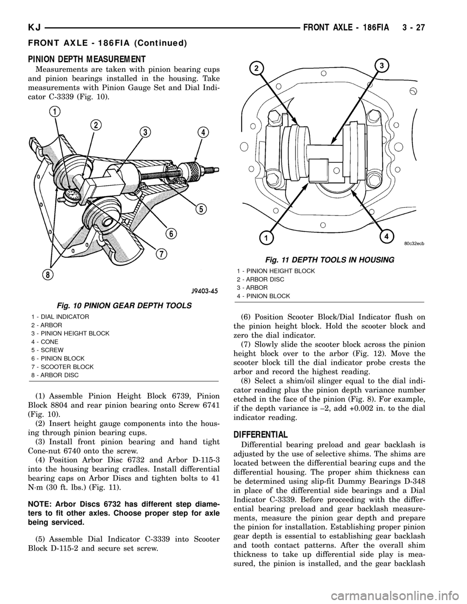
and pinion bearings installed in the housing. Take
measurements with Pinion Gauge Set and Dial Indi-
cator C-3339 (Fig. 10).
(1) Assemble Pinion Height Block 6739, Pinion
Block 8804 and rear pinion bearing onto Screw 6741
(Fig. 10).
(2) Insert height gauge components into the hous-
ing through pinion bearing cups.
(3) Install front pinion bearing and hand tight
Cone-nut 6740 onto the screw.
(4) Position Arbor Disc 6732 and Arbor D-115-3
into the housing bearing cradles. Install differential
bearing caps on Arbor Discs and tighten bolts to 41
N´m (30 ft. lbs.) (Fig. 11).
NOTE: Arbor Discs 6732 has different step diame-
ters to fit other axles. Choose proper step for axle
being serviced.
(5) Assemble Dial Indicator C-3339 into Scooter
Block D-115-2 and secure set screw.(6) Position Scooter Block/Dial Indicator flush on
the pinion height block. Hold the scooter block and
zero the dial indicator.
(7) Slowly slide the scooter block across the pinion
height block over to the arbor (Fig. 12). Move the
scooter block till the dial indicator probe crests the
arbor and record the highest reading.
(8) Select a shim/oil slinger equal to the dial indi-
cator reading plus the pinion depth variance number
etched in the face of the pinion (Fig. 8). For example,
if the depth variance is ±2, add +0.002 in. to the dial
indicator reading.
DIFFERENTIAL
Differential bearing preload and gear backlash is
adjusted by the use of selective shims. The shims are
located between the differential bearing cups and the
differential housing. The proper shim thickness can
be determined using slip-fit Dummy Bearings D-348
in place of the differential side bearings and a Dial
Indicator C-3339. Before proceeding with the differ-
ential bearing preload and gear backlash measure-
ments, measure the pinion gear depth and prepare
the pinion for installation. Establishing proper pinion
gear depth is essential to establishing gear backlash
and tooth contact patterns. After the overall shim
thickness to take up differential side play is mea-
sured, the pinion is installed, and the gear backlash
Fig. 10 PINION GEAR DEPTH TOOLS
1 - DIAL INDICATOR
2 - ARBOR
3 - PINION HEIGHT BLOCK
4 - CONE
5 - SCREW
6 - PINION BLOCK
7 - SCOOTER BLOCK
8 - ARBOR DISC
Fig. 11 DEPTH TOOLS IN HOUSING
1 - PINION HEIGHT BLOCK
2 - ARBOR DISC
3 - ARBOR
4 - PINION BLOCK
KJFRONT AXLE - 186FIA 3 - 27
FRONT AXLE - 186FIA (Continued)
Page 93 of 1803

INSTALLATION
(1) Install differential case bearings with Installer
C-3716-A and Handle C-4171 (Fig. 45).
(2) Install differential into the housing.
PINION GEAR/RING GEAR
REMOVAL
NOTE: The ring gear and pinion are serviced as a
matched set. Never replace ring gear without
replacing the matched pinion gear.
(1) Raise and support vehicle
(2) Mark pinion companion flange and propeller
shaft for installation alignment.
(3) Remove propeller shaft from pinion companion
flange and tie propeller shaft to underbody.
(4) Remove axle assembly from the vehicle.
(5) Remove differential from axle housing.
(6) Place differential case in a vise with soft metal
jaw (Fig. 46).
(7) Remove bolts holding ring gear to differential
case.
(8) Driver ring gear off the differential case with a
rawhide hammer (Fig. 46).(9) With Spanner Wrench 6958 and a short length
of 1 in. pipe, hold pinion companion flange and
remove pinion nut (Fig. 47).
Fig. 45 DIFFERENTIAL CASE BEARINGS
1 - HANDLE
2 - DIFFERENTIAL
3 - BEARING
4 - INSTALLER
Fig. 46 RING GEAR
1 - DIFFERENTIAL CASE
2 - RING GEAR
3 - HAMMER
Fig. 47 PINION COMPANION FLANGE
1 - SPANNER WRENCH
2 - PINION COMPANION FLANGE
3 - 44 FRONT AXLE - 186FIAKJ
DIFFERENTIAL CASE BEARINGS (Continued)