2002 JEEP LIBERTY service
[x] Cancel search: servicePage 101 of 1803

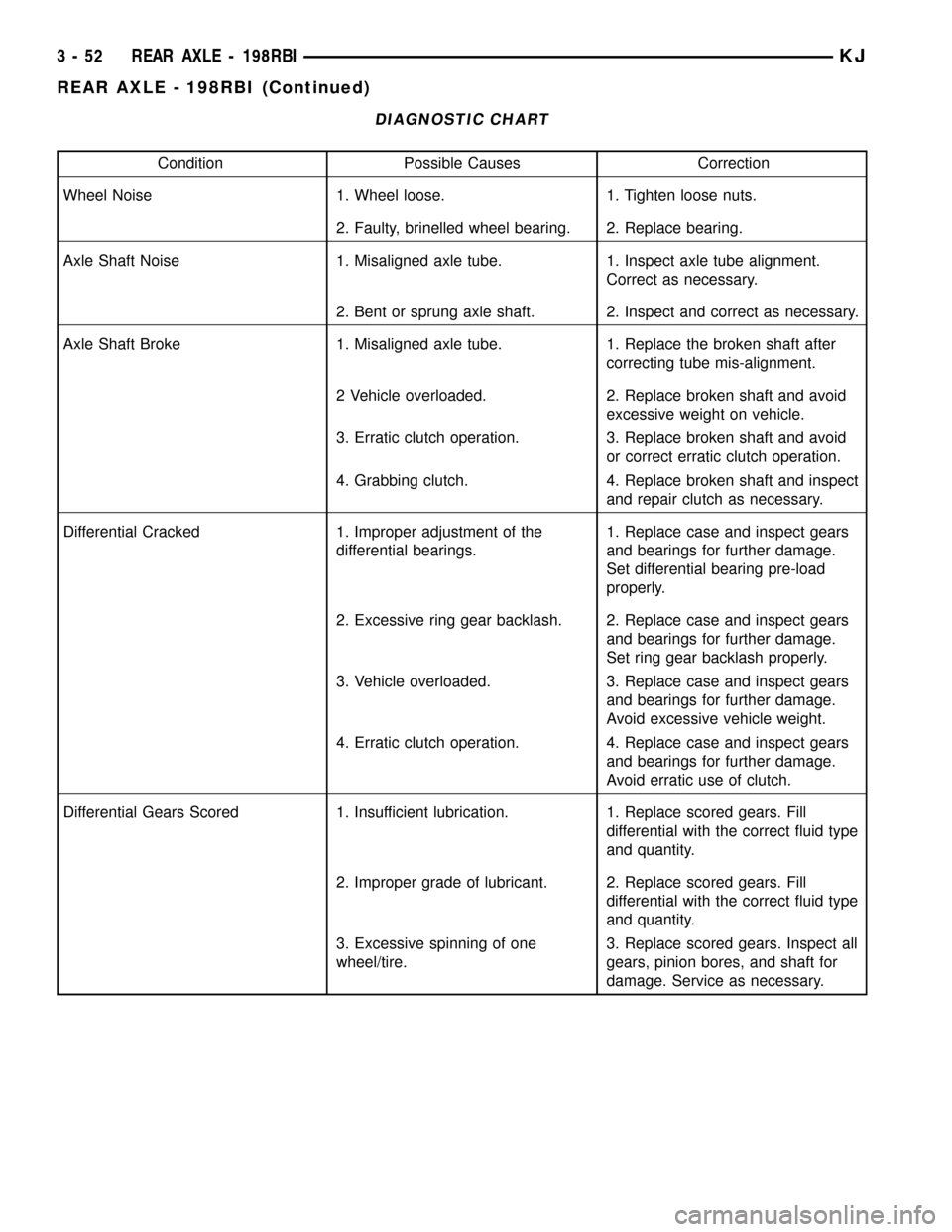
DIAGNOSTIC CHART
Condition Possible Causes Correction
Wheel Noise 1. Wheel loose. 1. Tighten loose nuts.
2. Faulty, brinelled wheel bearing. 2. Replace bearing.
Axle Shaft Noise 1. Misaligned axle tube. 1. Inspect axle tube alignment.
Correct as necessary.
2. Bent or sprung axle shaft. 2. Inspect and correct as necessary.
Axle Shaft Broke 1. Misaligned axle tube. 1. Replace the broken shaft after
correcting tube mis-alignment.
2 Vehicle overloaded. 2. Replace broken shaft and avoid
excessive weight on vehicle.
3. Erratic clutch operation. 3. Replace broken shaft and avoid
or correct erratic clutch operation.
4. Grabbing clutch. 4. Replace broken shaft and inspect
and repair clutch as necessary.
Differential Cracked 1. Improper adjustment of the
differential bearings.1. Replace case and inspect gears
and bearings for further damage.
Set differential bearing pre-load
properly.
2. Excessive ring gear backlash. 2. Replace case and inspect gears
and bearings for further damage.
Set ring gear backlash properly.
3. Vehicle overloaded. 3. Replace case and inspect gears
and bearings for further damage.
Avoid excessive vehicle weight.
4. Erratic clutch operation. 4. Replace case and inspect gears
and bearings for further damage.
Avoid erratic use of clutch.
Differential Gears Scored 1. Insufficient lubrication. 1. Replace scored gears. Fill
differential with the correct fluid type
and quantity.
2. Improper grade of lubricant. 2. Replace scored gears. Fill
differential with the correct fluid type
and quantity.
3. Excessive spinning of one
wheel/tire.3. Replace scored gears. Inspect all
gears, pinion bores, and shaft for
damage. Service as necessary.
3 - 52 REAR AXLE - 198RBIKJ
REAR AXLE - 198RBI (Continued)
Page 105 of 1803

PINION GEAR DEPTH VARIANCE
Original Pinion
Gear Depth
VarianceReplacement Pinion Gear Depth Variance
24232221 0 +1 +2 +3 +4
+4+0.008 +0.007 +0.006 +0.005 +0.004 +0.003 +0.002 +0.001 0
+3+0.007 +0.006 +0.005 +0.004 +0.003 +0.002 +0.001 020.001
+2+0.006 +0.005 +0.004 +0.003 +0.002 +0.001 020.00120.002
+1+0.005 +0.004 +0.003 +0.002 +0.001 020.00120.00220.003
0+0.004 +0.003 +0.002 +0.001 020.00120.00220.00320.004
21+0.003 +0.002 +0.001 020.00120.00220.00320.00420.005
22+0.002 +0.001 020.00120.00220.00320.00420.00520.006
23+0.001 020.00120.00220.00320.00420.00520.00620.007
24020.00120.00220.00320.00420.00520.00620.00720.008
PINION DEPTH MEASUREMENT
Measurements are taken with pinion cups and pin-
ion bearings installed in the housing. Take measure-
ments with a Pinion Gauge Set, Pinion Block 6735,
Arbor Discs 6732 and Dial Indicator C-3339 (Fig. 11).
(1) Assemble Pinion Height Block 6739, PinionBlock 6735 and rear pinion bearing onto Screw 6741
(Fig. 11).
(2) Insert assembled height gauge components,
rear bearing and screw into the housing through pin-
ion bearing cups (Fig. 12).
(3) Install front pinion bearing and Cone 6740
hand tight.
(4) Place Arbor Disc 6732 on Arbor D-115-3 in posi-
tion in the housing side bearing cradles (Fig. 13).
Install differential bearing caps on Arbor Discs and
tighten cap bolts. Refer to the Torque Specifications.
NOTE: Arbor Discs 6732 have different step diame-
ters to fit other axle sizes. Pick correct size step for
axle being serviced.
Fig. 11 PINION DEPTH TOOLS
1 - DIAL INDICATOR
2 - ARBOR
3 - PINION HEIGHT BLOCK
4 - CONE
5 - SCREW
6 - PINION BLOCK
7 - SCOOTER BLOCK
8 - ARBOR DISC
Fig. 12 PINION HEIGHT BLOCK
1 - PINION BLOCK
2 - PINION HEIGHT BLOCK
3 - 56 REAR AXLE - 198RBIKJ
REAR AXLE - 198RBI (Continued)
Page 123 of 1803

(6) Install the bearing caps in their original loca-
tions (Fig. 50).
(7) Loosely install differential bearing cap bolts.
(8) Remove axle housing spreader.
(9) Tighten the bearing cap bolts to 64-91 N´m
(47-67 ft. lbs.).
(10) Install the axle shafts.
(11) Apply a 6.35mm (1/4 in.) bead of red Mopar
Silicone Rubber Sealant or equivalent to the housing
cover (Fig. 51).
CAUTION: If cover is not installed within 3 to 5 min-
utes, the cover must be cleaned and new RTV
applied or adhesion quality will be compromised.
(12) Install the cover and tighten cover bolts in a
criss-cross pattern to 38-45 N´m (28-33 ft. lbs.).
(13) Refill the differential with lubricant and
install fill plug.
(14) Remove support and lower the vehicle.
DIFFERENTIAL - TRAC-LOK
DIAGNOSIS AND TESTING - TRAC-LOKT
The most common problem is a chatter noise when
turning corners. Before removing the unit for repair,
drain, flush and refill the axle with the specified
lubricant. A container of Mopar Trac-loktLubricant
(friction modifier) should be added after repair ser-
vice or during a lubricant change.
After changing the lubricant, drive the vehicle and
make 10 to 12 slow, figure-eight turns. This maneu-
ver will pump lubricant through the clutches. This
will correct the condition in most instances. If the
chatter persists, clutch damage could have occurred.
DIFFERENTIAL TEST
The differential can be tested without removing the
differential case by measuring rotating torque. Make
sure brakes are not dragging during this measure-
ment.
(1) Place blocks in front and rear of both front
wheels.
(2) Raise one rear wheel until it is completely off
the ground.
(3) Engine off, transmission in neutral, and park-
ing brake off.
(4) Remove wheel and bolt Special Tool 6790 or
equivalent tool to studs.
(5) Use torque wrench on special tool to rotate
wheel and read rotating torque (Fig. 52).
(6) If rotating torque is less than 41 N´m (56 ft.
lbs.) or more than 271 N´m (200 ft. lbs.) on either
wheel the unit should be serviced.
Fig. 50 BEARING CAP REFERENCE
1 - REFERENCE LETTERS
2 - REFERENCE LETTERS
Fig. 51 DIFFERENTIAL COVER - TYPICAL
1 - SEALING SURFACE
2 - SEALANT BEAD
3 - SEALANT THICKNESS
3 - 74 REAR AXLE - 198RBIKJ
DIFFERENTIAL (Continued)
Page 124 of 1803

DISASSEMBLY
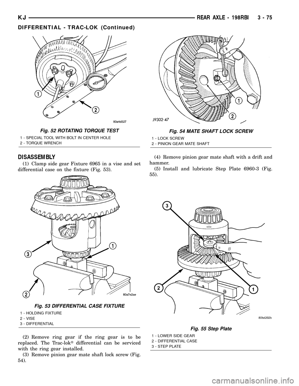
(1) Clamp side gear Fixture 6965 in a vise and set
differential case on the fixture (Fig. 53).
(2) Remove ring gear if the ring gear is to be
replaced. The Trac-loktdifferential can be serviced
with the ring gear installed.
(3) Remove pinion gear mate shaft lock screw (Fig.
54).(4) Remove pinion gear mate shaft with a drift and
hammer.
(5) Install and lubricate Step Plate 6960-3 (Fig.
55).
Fig. 52 ROTATING TORQUE TEST
1 - SPECIAL TOOL WITH BOLT IN CENTER HOLE
2 - TORQUE WRENCH
Fig. 53 DIFFERENTIAL CASE FIXTURE
1 - HOLDING FIXTURE
2 - VISE
3 - DIFFERENTIAL
Fig. 54 MATE SHAFT LOCK SCREW
1 - LOCK SCREW
2 - PINION GEAR MATE SHAFT
Fig. 55 Step Plate
1 - LOWER SIDE GEAR
2 - DIFFERENTIAL CASE
3 - STEP PLATE
KJREAR AXLE - 198RBI 3 - 75
DIFFERENTIAL - TRAC-LOK (Continued)
Page 128 of 1803

DIFFERENTIAL CASE
BEARINGS
REMOVAL
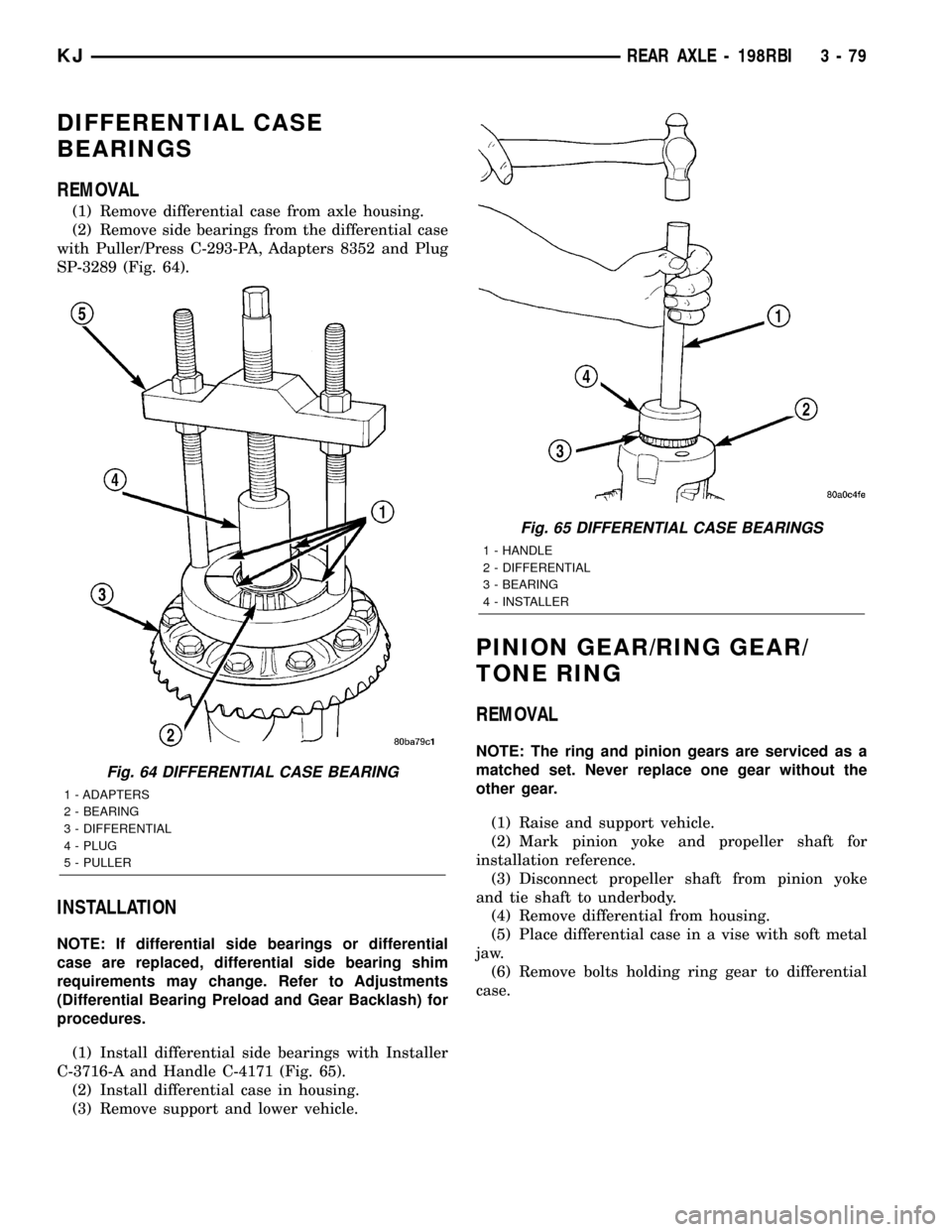
(1) Remove differential case from axle housing.
(2) Remove side bearings from the differential case
with Puller/Press C-293-PA, Adapters 8352 and Plug
SP-3289 (Fig. 64).
INSTALLATION
NOTE: If differential side bearings or differential
case are replaced, differential side bearing shim
requirements may change. Refer to Adjustments
(Differential Bearing Preload and Gear Backlash) for
procedures.
(1) Install differential side bearings with Installer
C-3716-A and Handle C-4171 (Fig. 65).
(2) Install differential case in housing.
(3) Remove support and lower vehicle.
PINION GEAR/RING GEAR/
TONE RING
REMOVAL
NOTE: The ring and pinion gears are serviced as a
matched set. Never replace one gear without the
other gear.
(1) Raise and support vehicle.
(2) Mark pinion yoke and propeller shaft for
installation reference.
(3) Disconnect propeller shaft from pinion yoke
and tie shaft to underbody.
(4) Remove differential from housing.
(5) Place differential case in a vise with soft metal
jaw.
(6) Remove bolts holding ring gear to differential
case.
Fig. 64 DIFFERENTIAL CASE BEARING
1 - ADAPTERS
2 - BEARING
3 - DIFFERENTIAL
4 - PLUG
5 - PULLER
Fig. 65 DIFFERENTIAL CASE BEARINGS
1 - HANDLE
2 - DIFFERENTIAL
3 - BEARING
4 - INSTALLER
KJREAR AXLE - 198RBI 3 - 79
Page 135 of 1803

REAR AXLE-81/4
TABLE OF CONTENTS
page page
REAR AXLE-81/4
DESCRIPTION.........................86
OPERATION...........................86
DIAGNOSIS AND TESTING - AXLE..........88
REMOVAL.............................91
INSTALLATION.........................91
ADJUSTMENTS........................92
SPECIFICATIONS
REAR AXLE..........................98
SPECIAL TOOLS
8 1/4 AXLE..........................98
AXLE SHAFTS
REMOVAL............................101
INSTALLATION........................101
AXLE SHAFT SEALS
REMOVAL............................101
INSTALLATION........................102
AXLE BEARINGS
REMOVAL............................102
INSTALLATION........................102PINION SEAL
REMOVAL............................102
INSTALLATION........................103
DIFFERENTIAL
REMOVAL............................104
DISASSEMBLY........................105
ASSEMBLY...........................105
INSTALLATION........................105
DIFFERENTIAL - TRAC-LOK
DIAGNOSIS AND TESTING - TRAC-LOKT....106
DISASSEMBLY........................107
CLEANING...........................109
INSPECTION.........................109
ASSEMBLY...........................109
DIFFERENTIAL CASE BEARINGS
REMOVAL............................110
INSTALLATION........................110
PINION GEAR/RING GEAR/TONE RING
REMOVAL............................110
INSTALLATION........................112
REAR AXLE-81/4
DESCRIPTION
The axle housings consist of a cast iron center sec-
tion with axle tubes extending from either side. The
tubes are pressed into and welded to the differential
housing to form a one-piece axle housing. The axles
are equipped with semi-floating axle shafts, meaning
vehicle loads are supported by the axle shaft and
bearings. The axle shafts are retained by C-locks in
the differential side gears.
The differential case is a one-piece design. The dif-
ferential pinion mate shaft is retained with a
threaded pin. Differential bearing preload and ring
gear backlash are set and maintained by threaded
adjusters at the outside of the differential housing.
Pinion bearing preload is set and maintained by the
use of a collapsible spacer.
The differential cover provides a means for inspec-
tion and service without removing the complete axlefrom the vehicle. A vent hose is used to relieve inter-
nal pressure caused by lubricant vaporization and
internal expansion.
Axles equipped with a Trac-Loktdifferential are
optional. A differential has a one-piece differential
case, and the same internal components as a stan-
dard differential, plus two clutch disc packs.
OPERATION
The axle receives power from the transmission/
transfer case through the rear propeller shaft. The
rear propeller shaft is connected to the pinion gear
which rotates the differential through the gear mesh
with the ring gear bolted to the differential case. The
engine power is transmitted to the axle shafts
through the pinion mate and side gears. The side
gears are splined to the axle shafts.
3 - 86 REAR AXLE-81/4KJ
Page 138 of 1803

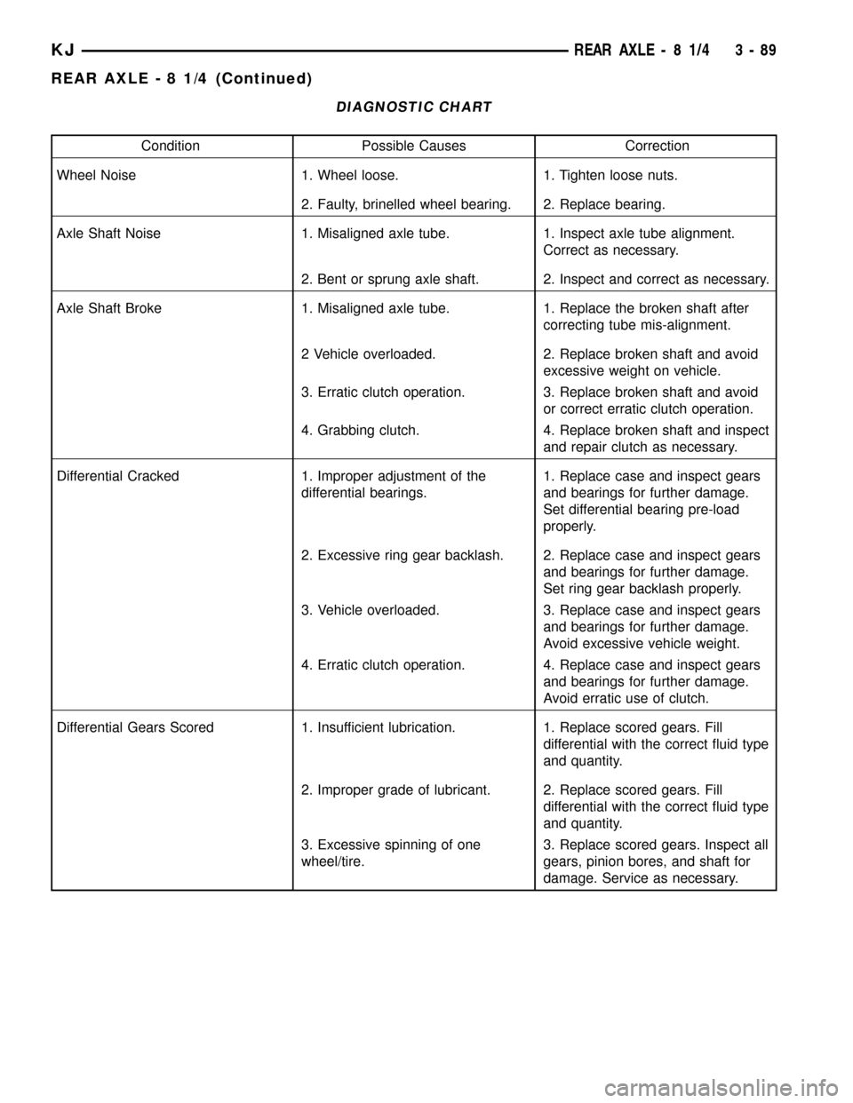
DIAGNOSTIC CHART
Condition Possible Causes Correction
Wheel Noise 1. Wheel loose. 1. Tighten loose nuts.
2. Faulty, brinelled wheel bearing. 2. Replace bearing.
Axle Shaft Noise 1. Misaligned axle tube. 1. Inspect axle tube alignment.
Correct as necessary.
2. Bent or sprung axle shaft. 2. Inspect and correct as necessary.
Axle Shaft Broke 1. Misaligned axle tube. 1. Replace the broken shaft after
correcting tube mis-alignment.
2 Vehicle overloaded. 2. Replace broken shaft and avoid
excessive weight on vehicle.
3. Erratic clutch operation. 3. Replace broken shaft and avoid
or correct erratic clutch operation.
4. Grabbing clutch. 4. Replace broken shaft and inspect
and repair clutch as necessary.
Differential Cracked 1. Improper adjustment of the
differential bearings.1. Replace case and inspect gears
and bearings for further damage.
Set differential bearing pre-load
properly.
2. Excessive ring gear backlash. 2. Replace case and inspect gears
and bearings for further damage.
Set ring gear backlash properly.
3. Vehicle overloaded. 3. Replace case and inspect gears
and bearings for further damage.
Avoid excessive vehicle weight.
4. Erratic clutch operation. 4. Replace case and inspect gears
and bearings for further damage.
Avoid erratic use of clutch.
Differential Gears Scored 1. Insufficient lubrication. 1. Replace scored gears. Fill
differential with the correct fluid type
and quantity.
2. Improper grade of lubricant. 2. Replace scored gears. Fill
differential with the correct fluid type
and quantity.
3. Excessive spinning of one
wheel/tire.3. Replace scored gears. Inspect all
gears, pinion bores, and shaft for
damage. Service as necessary.
KJREAR AXLE - 8 1/4 3 - 89
REAR AXLE - 8 1/4 (Continued)
Page 142 of 1803

PINION GEAR DEPTH VARIANCE
Original Pinion
Gear Depth
VarianceReplacement Pinion Gear Depth Variance
24232221 0 +1 +2 +3 +4
+4+0.008 +0.007 +0.006 +0.005 +0.004 +0.003 +0.002 +0.001 0
+3+0.007 +0.006 +0.005 +0.004 +0.003 +0.002 +0.001 020.001
+2+0.006 +0.005 +0.004 +0.003 +0.002 +0.001 020.00120.002
+1+0.005 +0.004 +0.003 +0.002 +0.001 020.00120.00220.003
0+0.004 +0.003 +0.002 +0.001 020.00120.00220.00320.004
21+0.003 +0.002 +0.001 020.00120.00220.00320.00420.005
22+0.002 +0.001 020.00120.00220.00320.00420.00520.006
23+0.001 020.00120.00220.00320.00420.00520.00620.007
24020.00120.00220.00320.00420.00520.00620.00720.008
PINION DEPTH MEASUREMENT
Measurements are taken with pinion bearing cups and
pinion bearings installed in the housing. Take measure-
ments with Pinion Gauge Set and Dial Indicator C-3339.
(1) Assemble Pinion Height Block 6739, Pinion
Block 8540 and rear pinion bearing onto Screw 6741
(Fig. 10).(2) Insert assembled height gauge components,
rear bearing, and screw into the housing through
pinion bearing cups (Fig. 11).
(3) Install front pinion bearing and Cone-Nut 6740
hand tight (Fig. 10).
(4) Place Arbor Disc 8541 on Arbor D-115-3 in posi-
tion in the housing side bearing cradles (Fig. 12).
Install differential bearing caps on Arbor Discs and
tighten cap bolts to 41 N´m (30 ft. lbs.).
NOTE: Arbor Discs 8541 has different step diame-
ters to fit other axles. Choose proper step for axle
being serviced.
(5) Assemble Dial Indicator C-3339 into Scooter
Block D-115-2 and secure set screw.
Fig. 10 Pinion Depth Gauge Tools
1 - DIAL INDICATOR
2 - ARBOR
3 - PINION HEIGHT BLOCK
4 - CONE
5 - SCREW
6 - PINION BLOCK
7 - SCOOTER BLOOK
8 - ARBOR DISC
Fig. 11 Pinion Height Block
1 - PINION BLOCK
2 - PINION HEIGHT BLOCK
KJREAR AXLE - 8 1/4 3 - 93
REAR AXLE - 8 1/4 (Continued)