2002 JEEP LIBERTY run flat
[x] Cancel search: run flatPage 1455 of 1803
TIRES/WHEELS
TABLE OF CONTENTS
page page
TIRES/WHEELS
DIAGNOSIS AND TESTING - TIRES AND
WHEEL RUNOUT......................1
STANDARD PROCEDURE
STANDARD PROCEDURE - TIRE ROTATION . 2
STANDARD PROCEDURE - MATCH
MOUNTING...........................3
STANDARD PROCEDURE - WHEEL
BALANCING..........................4
TIRES
DESCRIPTION
DESCRIPTION - TIRES..................6
DESCRIPTION - RADIAL-PLY TIRES........6
DESCRIPTION - SPARE TIRE
&TEMPORARY........................6
DESCRIPTION - REPLACEMENT TIRES.....7
DIAGNOSIS AND TESTING
DIAGNOSIS AND TESTING - TIRE
INFLATION...........................7
DIAGNOSIS AND TESTING - TREAD WEAR
INDICATORS..........................8
DIAGNOSIS AND TESTING - TIRE WEAR
PATTERNS...........................8DIAGNOSIS AND TESTING - TIRE NOISE
OR VIBRATION........................8
STANDARD PROCEDURE - REPAIRING
LEAKS...............................8
CLEANING.............................8
SPECIFICATIONS........................8
SPARE TIRE
REMOVAL.............................8
INSTALLATION..........................9
WHEELS
DESCRIPTION..........................9
DIAGNOSIS AND TESTING - WHEELS.......10
STANDARD PROCEDURE
STANDARD PROCEDURE - WHEEL
REPLACEMENT.......................10
STANDARD PROCEDURE - WHEEL
MOUNTING..........................10
SPECIFICATIONS
SPECIFICATION......................11
STUDS
REMOVAL.............................11
INSTALLATION.........................11
TIRES/WHEELS
DIAGNOSIS AND TESTING - TIRES AND
WHEEL RUNOUT
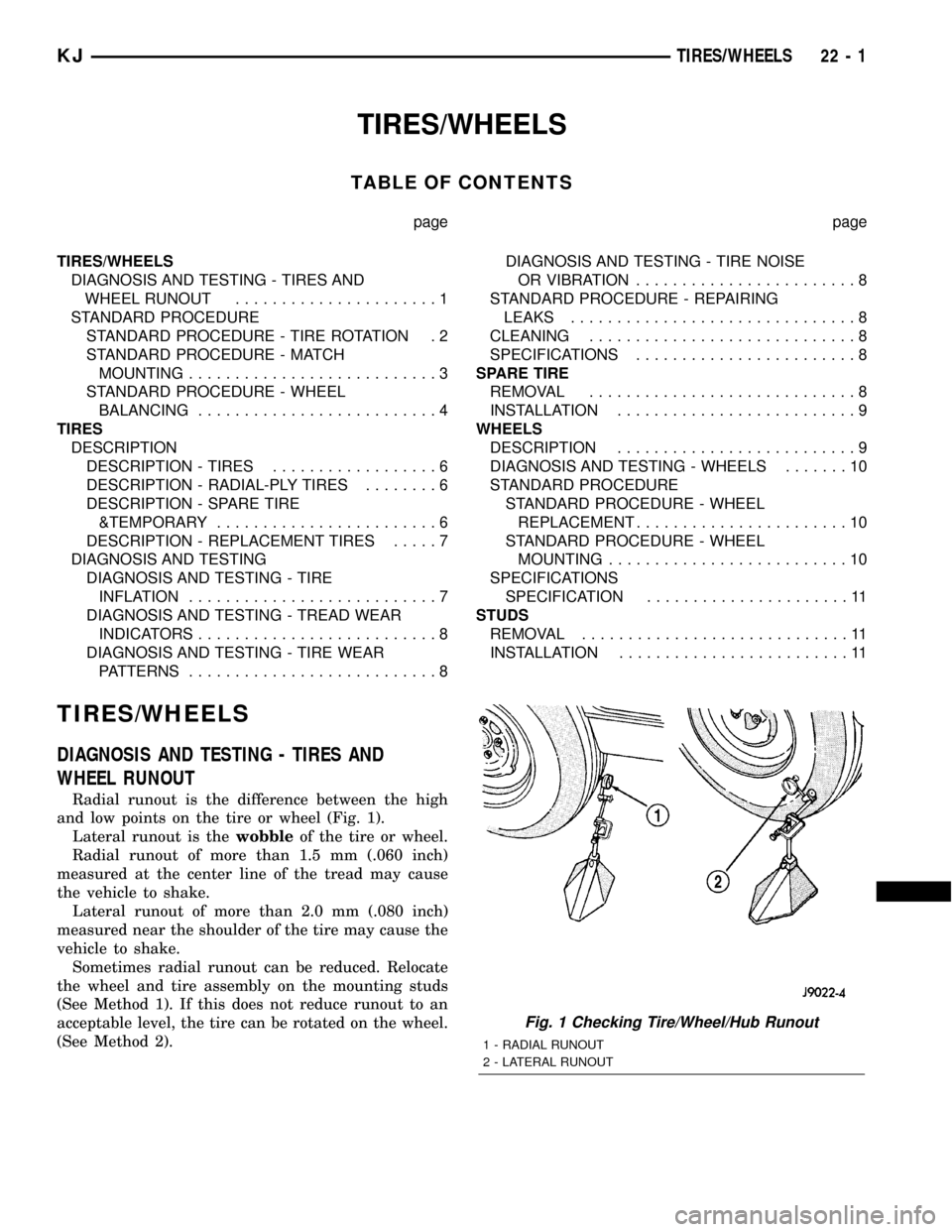
Radial runout is the difference between the high
and low points on the tire or wheel (Fig. 1).
Lateral runout is thewobbleof the tire or wheel.
Radial runout of more than 1.5 mm (.060 inch)
measured at the center line of the tread may cause
the vehicle to shake.
Lateral runout of more than 2.0 mm (.080 inch)
measured near the shoulder of the tire may cause the
vehicle to shake.
Sometimes radial runout can be reduced. Relocate
the wheel and tire assembly on the mounting studs
(See Method 1). If this does not reduce runout to an
acceptable level, the tire can be rotated on the wheel.
(See Method 2).
Fig. 1 Checking Tire/Wheel/Hub Runout
1 - RADIAL RUNOUT
2 - LATERAL RUNOUT
KJTIRES/WHEELS 22 - 1
Page 1456 of 1803
METHOD 1 (RELOCATE WHEEL ON HUB)
(1) Drive vehicle a short distance to eliminate tire
flat spotting from a parked position.
(2) Check wheel bearings and adjust if adjustable
or replace if necessary.
(3) Check the wheel mounting surface.
(4) Relocate wheel on the mounting, two studs
over from the original position.
(5) Tighten wheel nuts until all are properly
torqued, to eliminate brake distortion.
(6) Check radial runout. If still excessive, mark
tire sidewall, wheel, and stud at point of maximum
runout and proceed to Method 2.
METHOD 2 (RELOCATE TIRE ON WHEEL)
NOTE: Rotating the tire on wheel is particularly
effective when there is runout in both tire and
wheel.
(1) Remove tire from wheel and mount wheel on
service dynamic balance machine.
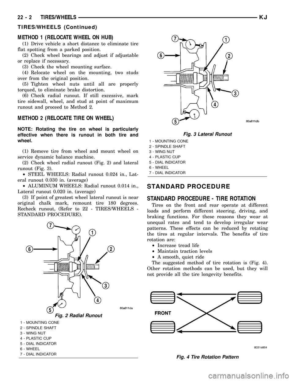
(2) Check wheel radial runout (Fig. 2) and lateral
runout (Fig. 3).
²STEEL WHEELS: Radial runout 0.024 in., Lat-
eral runout 0.030 in. (average)
²ALUMINUM WHEELS: Radial runout 0.014 in.,
Lateral runout 0.020 in. (average)
(3) If point of greatest wheel lateral runout is near
original chalk mark, remount tire 180 degrees.
Recheck runout, (Refer to 22 - TIRES/WHEELS -
STANDARD PROCEDURE).
STANDARD PROCEDURE
STANDARD PROCEDURE - TIRE ROTATION
Tires on the front and rear operate at different
loads and perform different steering, driving, and
braking functions. For these reasons they wear at
unequal rates and tend to develop irregular wear
patterns. These effects can be reduced by rotating
the tires at regular intervals. The benefits of tire
rotation are:
²Increase tread life
²Maintain traction levels
²A smooth, quiet ride
The suggested method of tire rotation is (Fig. 4).
Other rotation methods can be used, but they will
not provide all the tire longevity benefits.
Fig. 2 Radial Runout
1 - MOUNTING CONE
2 - SPINDLE SHAFT
3 - WING NUT
4 - PLASTIC CUP
5 - DIAL INDICATOR
6 - WHEEL
7 - DIAL INDICATOR
Fig. 3 Lateral Runout
1 - MOUNTING CONE
2 - SPINDLE SHAFT
3 - WING NUT
4 - PLASTIC CUP
5 - DIAL INDICATOR
6 - WHEEL
7 - DIAL INDICATOR
Fig. 4 Tire Rotation Pattern
22 - 2 TIRES/WHEELSKJ
TIRES/WHEELS (Continued)
Page 1462 of 1803
DIAGNOSIS AND TESTING - TREAD WEAR
INDICATORS
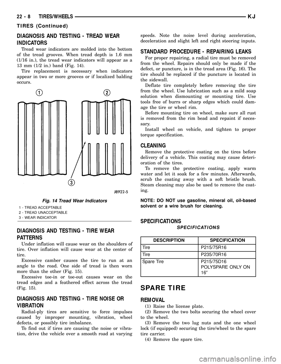
Tread wear indicators are molded into the bottom
of the tread grooves. When tread depth is 1.6 mm
(1/16 in.), the tread wear indicators will appear as a
13 mm (1/2 in.) band (Fig. 14).
Tire replacement is necessary when indicators
appear in two or more grooves or if localized balding
occurs.
DIAGNOSIS AND TESTING - TIRE WEAR
PATTERNS
Under inflation will cause wear on the shoulders of
tire. Over inflation will cause wear at the center of
tire.
Excessive camber causes the tire to run at an
angle to the road. One side of tread is then worn
more than the other (Fig. 15).
Excessive toe-in or toe-out causes wear on the
tread edges and a feathered effect across the tread
(Fig. 15).
DIAGNOSIS AND TESTING - TIRE NOISE OR
VIBRATION
Radial-ply tires are sensitive to force impulses
caused by improper mounting, vibration, wheel
defects, or possibly tire imbalance.
To find out if tires are causing the noise or vibra-
tion, drive the vehicle over a smooth road at varyingspeeds. Note the noise level during acceleration,
deceleration and slight left and right steering inputs.
STANDARD PROCEDURE - REPAIRING LEAKS
For proper repairing, a radial tire must be removed
from the wheel. Repairs should only be made if the
defect, or puncture, is in the tread area (Fig. 16). The
tire should be replaced if the puncture is located in
the sidewall.
Deflate tire completely before removing the tire
from the wheel. Use lubrication such as a mild soap
solution when dismounting or mounting tire. Use
tools free of burrs or sharp edges which could dam-
age the tire or wheel rim.
Before mounting tire on wheel, make sure all rust
is removed from the rim bead and repaint if neces-
sary.
Install wheel on vehicle, and tighten to proper
torque specification.
CLEANING
Remove the protective coating on the tires before
delivery of a vehicle. This coating may cause deteri-
oration of the tires.
To remove the protective coating, apply warm
water and let it soak for a few minutes. Afterwards,
scrub the coating away with a soft bristle brush.
Steam cleaning may also be used to remove the coat-
ing.
NOTE: DO NOT use gasoline, mineral oil, oil-based
solvent or a wire brush for cleaning.
SPECIFICATIONS
SPECIFICATIONS
DESCRIPTION SPECIFICATION
Tire P215/75R16
Tire P235/70R16
Spare Tire P215/75D16
POLYSPARE ONLY ON
169
SPARE TIRE
REMOVAL
(1) Raise the license plate.
(2) Remove the two bolts securing the wheel cover
to the wheel.
(3) Remove the two lug nuts and the one wheel
lock (if equipped) securing the tire/wheel to the spare
tire carrier.
(4) Remove the spare tire.
Fig. 14 Tread Wear Indicators
1 - TREAD ACCEPTABLE
2 - TREAD UNACCEPTABLE
3 - WEAR INDICATOR
22 - 8 TIRES/WHEELSKJ
TIRES (Continued)
Page 1464 of 1803
Initial inflation of the tire forces the bead over
these raised sections. In case of rapid loss of air pres-
sure, the raised sections help hold the tire on the
wheel.
The wheel studs and nuts are designed for specific
applications. All aluminum and some steel wheels
have wheel stud nuts with an enlarged nose. This
enlarged nose is necessary to ensure proper retention
of the wheels. Do not use replacement studs or nuts
with a different design or lesser quality.
DIAGNOSIS AND TESTING - WHEELS
Inspect wheels for:
²Excessive run out
²Dents or cracks
²Damaged wheel lug nut holes
²Air Leaks from any area or surface of the rim
NOTE: Do not attempt to repair a wheel by hammer-
ing, heating or welding.
If a wheel is damaged an original equipment
replacement wheel should be used. When obtaining
replacement wheels, they should be equivalent in
load carrying capacity. The diameter, width, offset,
pilot hole and bolt circle of the wheel should be the
same as the original wheel.
WARNING: FAILURE TO USE EQUIVALENT
REPLACEMENT WHEELS MAY ADVERSELY
AFFECT THE SAFETY AND HANDLING OF THE
VEHICLE. USED WHEELS ARE NOT RECOM-
MENDED. THE SERVICE HISTORY OF THE WHEEL
MAY HAVE INCLUDED SEVERE TREATMENT OR
VERY HIGH MILEAGE. THE RIM COULD FAIL WITH-
OUT WARNING.
STANDARD PROCEDURE
STANDARD PROCEDURE - WHEEL
REPLACEMENT
Wheels must be replaced if they have:
²Excessive runout
²Bent or dented
²Leak air through welds
²Have damaged bolt holes
Wheel repairs employing hammering, heating, or
welding are not allowed.
Original equipment wheels are available through
your dealer. Replacement wheels from any other
source should be equivalent in:
²Load carrying capacity
²Diameter
²Width
²Offset²Mounting configuration
Failure to use equivalent replacement wheels may
affect the safety and handling of your vehicle.
Replacement withusedwheels is not recommended.
Their service history may have included severe treat-
ment.
STANDARD PROCEDURE - WHEEL MOUNTING
The wheel studs and nuts are designed for specific
applications. They must be replaced with equivalent
parts. Do not use replacement parts of lesser quality
or a substitute design. All aluminum and some steel
wheels have wheel stud nuts which feature an
enlarged nose. This enlarged nose is necessary to
ensure proper retention of the aluminum wheels.
NOTE: Do not use chrome plated lug nuts with
chrome plated wheels.
Before installing the wheel, be sure to remove any
build up of corrosion on the wheel mounting surfaces.
Ensure wheels are installed with good metal-to-metal
contact. Improper installation could cause loosening
of wheel nuts. This could affect the safety and han-
dling of your vehicle.
To install the wheel, first position it properly on
the mounting surface. All wheel nuts should then be
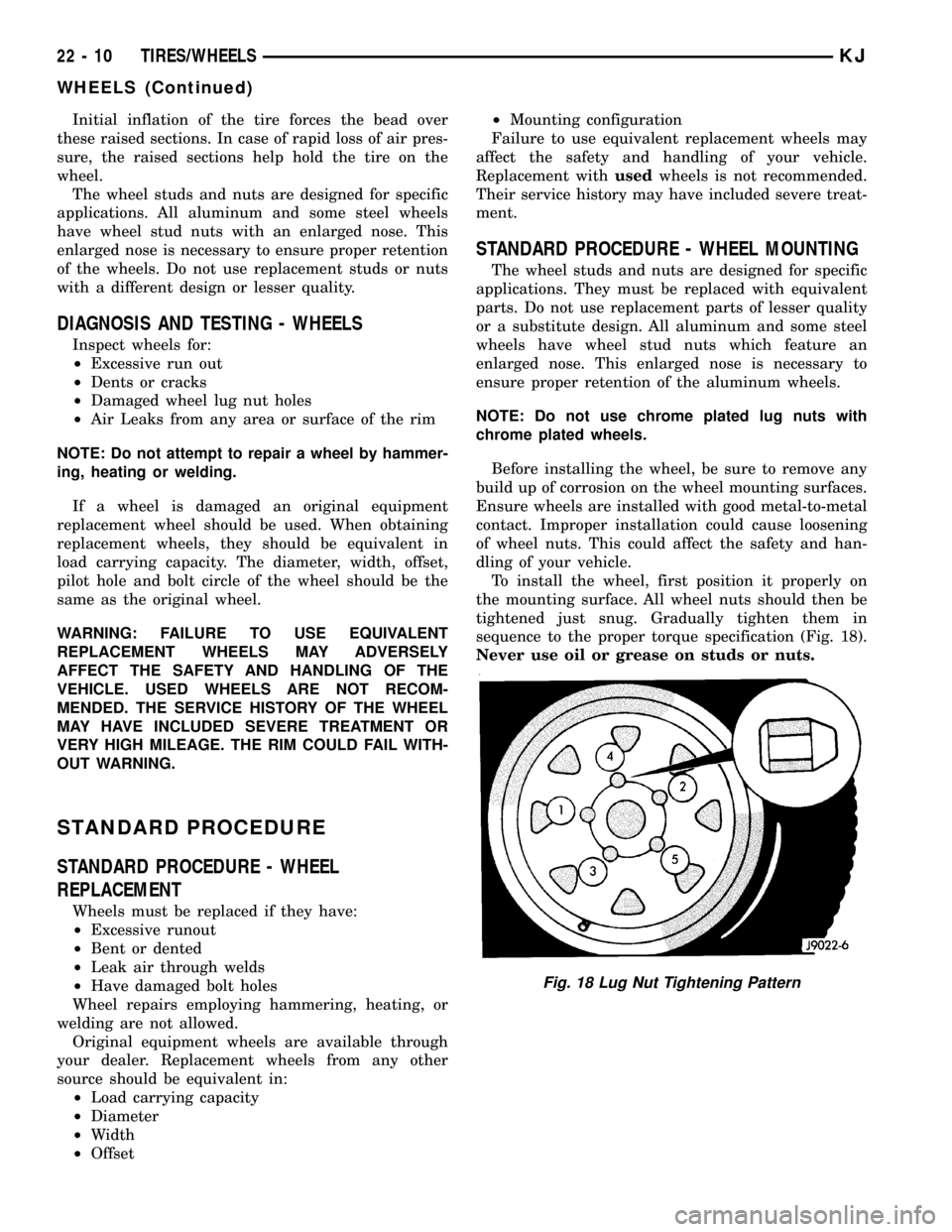
tightened just snug. Gradually tighten them in
sequence to the proper torque specification (Fig. 18).
Never use oil or grease on studs or nuts.
Fig. 18 Lug Nut Tightening Pattern
22 - 10 TIRES/WHEELSKJ
WHEELS (Continued)
Page 1594 of 1803
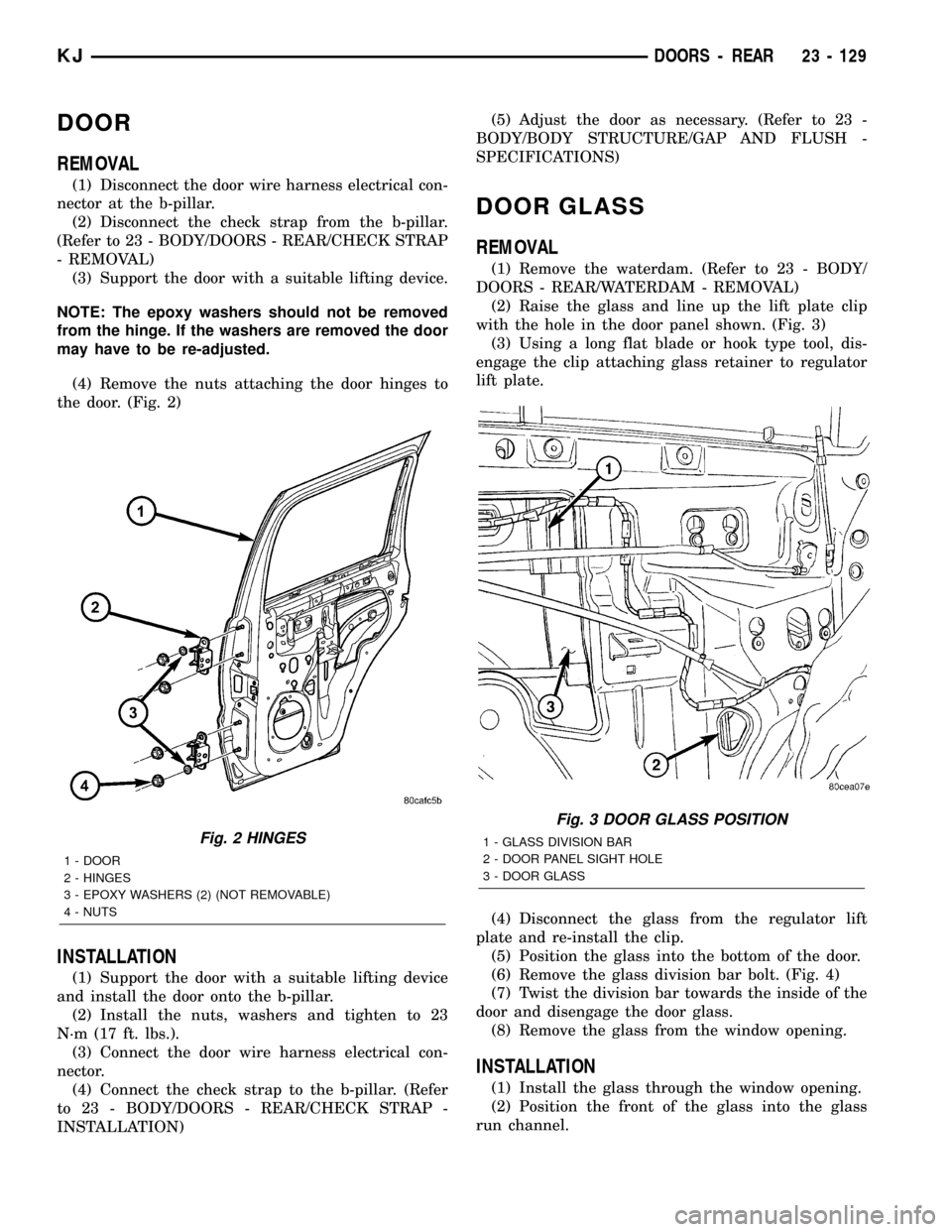
DOOR
REMOVAL
(1) Disconnect the door wire harness electrical con-
nector at the b-pillar.
(2) Disconnect the check strap from the b-pillar.
(Refer to 23 - BODY/DOORS - REAR/CHECK STRAP
- REMOVAL)
(3) Support the door with a suitable lifting device.
NOTE: The epoxy washers should not be removed
from the hinge. If the washers are removed the door
may have to be re-adjusted.
(4) Remove the nuts attaching the door hinges to
the door. (Fig. 2)
INSTALLATION
(1) Support the door with a suitable lifting device
and install the door onto the b-pillar.
(2) Install the nuts, washers and tighten to 23
N´m (17 ft. lbs.).
(3) Connect the door wire harness electrical con-
nector.
(4) Connect the check strap to the b-pillar. (Refer
to 23 - BODY/DOORS - REAR/CHECK STRAP -
INSTALLATION)(5) Adjust the door as necessary. (Refer to 23 -
BODY/BODY STRUCTURE/GAP AND FLUSH -
SPECIFICATIONS)
DOOR GLASS
REMOVAL
(1) Remove the waterdam. (Refer to 23 - BODY/
DOORS - REAR/WATERDAM - REMOVAL)
(2) Raise the glass and line up the lift plate clip
with the hole in the door panel shown. (Fig. 3)
(3) Using a long flat blade or hook type tool, dis-
engage the clip attaching glass retainer to regulator
lift plate.
(4) Disconnect the glass from the regulator lift
plate and re-install the clip.
(5) Position the glass into the bottom of the door.
(6) Remove the glass division bar bolt. (Fig. 4)
(7) Twist the division bar towards the inside of the
door and disengage the door glass.
(8) Remove the glass from the window opening.
INSTALLATION
(1) Install the glass through the window opening.
(2) Position the front of the glass into the glass
run channel.
Fig. 2 HINGES
1 - DOOR
2 - HINGES
3 - EPOXY WASHERS (2) (NOT REMOVABLE)
4 - NUTS
Fig. 3 DOOR GLASS POSITION
1 - GLASS DIVISION BAR
2 - DOOR PANEL SIGHT HOLE
3 - DOOR GLASS
KJDOORS - REAR 23 - 129
Page 1766 of 1803
TANK - REMOVAL, FUEL...............14-25
TANK CHECK VALVE - DESCRIPTION,
FUEL..............................14-28
TANK CHECK VALVE - INSTALLATION,
FUEL..............................14-28
TANK CHECK VALVE - OPERATION, FUEL . . 14-28
TANK CHECK VALVE - REMOVAL, FUEL . . . 14-28
TANK SKID PLATE - INSTALLATION,
FUEL...............................13-9
TANK SKID PLATE - REMOVAL, FUEL......13-9
TASK MANAGER - DESCRIPTION........25-17
TASK MANAGER - OPERATION..........25-21
TCM QUICK LEARN - STANDARD
PROCEDURE........................8E-21
TEMP INDICATOR - DESCRIPTION,
TRANS.............................8J-33
TEMP INDICATOR - OPERATION, TRANS . . 8J-34
TEMP SENSOR - DESCRIPTION,
AMBIENT...........................8M-9
TEMP SENSOR - OPERATION, AMBIENT . . . 8M-9
TEMPERATURE GAUGE - DESCRIPTION,
ENGINE............................8J-18
TEMPERATURE GAUGE - OPERATION,
ENGINE............................8J-18
TEMPERATURE SENSOR - DESCRIPTION,
BATTERY...........................8F-24
TEMPERATURE SENSOR - DESCRIPTION,
ENGINE COOLANT.....................7-19
TEMPERATURE SENSOR - DESCRIPTION,
INTAKE AIR .........................14-36
TEMPERATURE SENSOR - DESCRIPTION,
TRANSMISSION.....................21-170
TEMPERATURE SENSOR - DIAGNOSIS
AND TESTING, AMBIENT...............8M-9
TEMPERATURE SENSOR -
INSTALLATION, BATTERY..............8F-24
TEMPERATURE SENSOR -
INSTALLATION, ENGINE COOLANT........7-21
TEMPERATURE SENSOR -
INSTALLATION, INTAKE AIR............14-38
TEMPERATURE SENSOR - OPERATION,
BATTERY...........................8F-24
TEMPERATURE SENSOR - OPERATION,
ENGINE COOLANT.....................7-20
TEMPERATURE SENSOR - OPERATION,
INTAKE AIR .........................14-36
TEMPERATURE SENSOR - OPERATION,
TRANSMISSION.....................21-170
TEMPERATURE SENSOR - REMOVAL,
BATTERY...........................8F-24
TEMPERATURE SENSOR - REMOVAL,
ENGINE COOLANT.....................7-20
TEMPERATURE SENSOR - REMOVAL,
INTAKE AIR .........................14-37
TEMPERATURE SENSOR CIRCUIT -
DIAGNOSIS AND TESTING, AMBIENT.....8M-9
TENSIONER - DESCRIPTION, SEAT BELT . . 8O-36
TENSIONER - OPERATION, SEAT BELT....8O-36
TERMINAL - INSTALLATION.........8W-01-14
TERMINAL - REMOVAL.............8W-01-14
TEST - DIAGNOSIS AND TESTING, FUEL
PRESSURE LEAK DOWN................14-3
TEST - DIAGNOSIS AND TESTING, FUEL
PUMP AMPERAGE....................14-16
TEST - DIAGNOSIS AND TESTING, FUEL
PUMP CAPACITY.....................14-15
TEST - DIAGNOSIS AND TESTING, FUEL
PUMP PRESSURE....................14-15
TEST - DIAGNOSIS AND TESTING,
HYDRAULIC PRESSURE...............21-79
TEST - DIAGNOSIS AND TESTING, ROAD . . . 8P-2
TEST - STANDARD PROCEDURE,
BUILT-IN INDICATOR..................8F-10
TEST - STANDARD PROCEDURE,
HYDROMETER.......................8F-11
TEST - STANDARD PROCEDURE,
IGNITION-OFF DRAW..................8F-14
TEST - STANDARD PROCEDURE, LOAD . . . 8F-12
TEST - STANDARD PROCEDURE,
OPEN-CIRCUIT VOLTAGE
...............8F-12
TEST - STANDARD PROCEDURE,
VERIFICATION
........................8O-8
TEST MODE - DESCRIPTION, CIRCUIT
ACTUATION
..........................25-2
TEST MODE - DESCRIPTION, STATE
DISPLAY
............................25-2
TESTER - STANDARD PROCEDURE,
USING MIDTRONICS ELECTRICAL
.......8F-15TETHER ANCHOR - DESCRIPTION, CHILD . 8O-13
TETHER ANCHOR - OPERATION, CHILD . . . 8O-13
THEFT SECURITY - DESCRIPTION,
VEHICLE............................8Q-1
THEFT SECURITY - OPERATION, VEHICLE . . 8Q-3
THEFT SECURITY SYSTEM - DIAGNOSIS
AND TESTING, VEHICLE................8Q-6
THERMAL GUARD - DESCRIPTION.......8F-20
THERMAL GUARD - INSTALLATION......8F-20
THERMAL GUARD - OPERATION.........8F-20
THERMAL GUARD - REMOVAL..........8F-20
THERMOSTAT - DIAGNOSIS AND
TESTING............................7-21
THERMOSTAT - OPERATION, ENGINE
COOLANT............................7-21
THREAD REPAIR - STANDARD
PROCEDURE, ALUMINUM..............21-81
THREADED HOLE REPAIR -
DESCRIPTION......................Intro.-4
THREADS - STANDARD PROCEDURE,
REPAIR DAMAGED OR WORN............9-9
THROTTLE BODY - DESCRIPTION........14-43
THROTTLE BODY - INSTALLATION.......14-44
THROTTLE BODY - OPERATION.........14-43
THROTTLE BODY - REMOVAL...........14-43
THROTTLE CONTROL CABLE -
INSTALLATION.......................14-46
THROTTLE CONTROL CABLE - REMOVAL . . 14-45
THROTTLE POSITION SENSOR -
DESCRIPTION.........................14-47
THROTTLE POSITION SENSOR -
INSTALLATION.......................14-48
THROTTLE POSITION SENSOR -
OPERATION.........................14-47
THROTTLE POSITION SENSOR -
REMOVAL..........................14-47
TIE ROD END - INSTALLATION..........19-16
TIE ROD END - REMOVAL..............19-16
TIE ROD END REMOVAL TOOL, SPECIAL
TOOLS - OUTER.....................19-15
TIME INDICATOR - DESCRIPTION, FULL . . . 8J-29
TIME INDICATOR - DESCRIPTION, PART . . 8J-29
TIME INDICATOR - OPERATION, FULL....8J-30
TIME INDICATOR - OPERATION, PART....8J-29
TIMING - DESCRIPTION, VALVE..........9-71
TIMING - OPERATION, VALVE............9-71
TIMING - SPECIFICATIONS, IGNITION......8I-2
TIMING BELT / CHAIN COVER(S) -
INSTALLATION........................9-76
TIMING BELT / CHAIN COVER(S) -
REMOVAL...........................9-74
TIMING CHAIN WEAR, STANDARD
PROCEDURE - MEASURING.............9-71
TIRE - INSTALLATION, SPARE...........22-9
TIRE - REMOVAL, SPARE...............22-8
TIRE INFLATION - DIAGNOSIS AND
TESTING............................22-7
TIRE NOISE OR VIBRATION - DIAGNOSIS
AND TESTING........................22-8
TIRE ROTATION - STANDARD
PROCEDURE.........................22-2
TIRE &TEMPORARY - DESCRIPTION,
SPARE..............................22-6
TIRE WEAR PATTERNS - DIAGNOSIS
AND TESTING........................22-8
TIRES - DESCRIPTION.................22-6
TIRES - DESCRIPTION, RADIAL-PLY.......22-6
TIRES - DESCRIPTION, REPLACEMENT....22-7
TIRES AND WHEEL RUNOUT -
DIAGNOSIS AND TESTING..............22-1
TO GROUND - STANDARD PROCEDURE,
TESTING FOR A SHORT.............8W-01-9
TO GROUND ON FUSES POWERING
SEVERAL LOADS - STANDARD
PROCEDURE, TESTING FOR A SHORT . . 8W-01-9
TO USE WIRING DIAGRAMS -
DESCRIPTION, HOW................8W-01-1
TOE ADJUSTMENT - STANDARD
PROCEDURE..........................2-5
TOE ADJUSTMENT - STANDARD
PROCEDURE, CAMBER, CASTER..........2-5
TOOL, SPECIAL TOOLS - OUTER TIE
ROD END REMOVAL..................19-15
TOOLS - 3.7L ENGINE, SPECIAL
..........9-15
TOOLS - 8 1/4 AXLE, SPECIAL
...........3-98
TOOLS - BASE BRAKES, SPECIAL
.........5-7
TOOLS - BODY, SPECIAL
................23-5
TOOLS - COOLING, SPECIAL
.............7-14TOOLS - FRONT AXLE, SPECIAL..........3-34
TOOLS - FRONT SUSPENSION, SPECIAL....2-8
TOOLS - FUEL SYSTEM, SPECIAL........14-6
TOOLS - OUTER TIE ROD END REMOVAL
TOOL, SPECIAL......................19-15
TOOLS - POWER DISTRIBUTION
SYSTEMS, SPECIAL................8W-97-2
TOOLS - POWER STEERING PUMP,
SPECIAL...........................19-20
TOOLS - REAR AXLE, SPECIAL...........3-63
TOOLS - RFE TRANSMISSION, SPECIAL . . 21-120
TOOLS - STEERING COLUMN, SPECIAL....19-8
TOOLS - WIRING/TERMINAL, SPECIAL . 8W-01-10
TOOLS, BATTERY SYSTEM - SPECIAL.....8F-7
TOOLS, SPECIFICATIONS - SPECIAL....3-12,3-6
TOOLS, SPECIFICATIONS - SPECIAL......8F-24
TOP COVER - INSTALLATION,
INSTRUMENT PANEL.................23-153
TOP COVER - REMOVAL, INSTRUMENT
PANEL............................23-152
TORQUE - SPECIFICATIONS.............13-6
TORQUE CHART, SPECIFICATIONS . . 19-15,19-19,
19-8
TORQUE CHART, SPECIFICATIONS.....2-17,2-8
TORQUE CONVERTER - DESCRIPTION . . . 21-162
TORQUE CONVERTER - INSTALLATION . . . 21-167
TORQUE CONVERTER - OPERATION.....21-166
TORQUE CONVERTER - REMOVAL......21-167
TORQUE, EXCEPT DIESEL..............8F-23
TORQUE, GAS POWERED..............8F-38
TORQUE, IGNITION SYSTEM.............8I-3
TORQUE REFERENCES - DESCRIPTION . . Intro.-7
TORQUE, SPECIFICATIONS...............5-7
TORQUE, SPECIFICATIONS..............7-13
TORQUE, SPECIFICATIONS.............25-26
TORQUE, SPECIFICATIONS..............9-12
TORQUE, SPECIFICATIONS..............14-5
TORQUE, SPEED CONTROL.............8P-2
TOUCH-UP - DESCRIPTION, PAINT......23-163
TOW CONNECTOR - INSTALLATION,
TRAILER...........................8L-61
TOW CONNECTOR - REMOVAL, TRAILER . . 8L-61
TOW HOOK - INSTALLATION, FRONT......13-8
TOW HOOK - INSTALLATION, REAR.......13-8
TOW HOOK - REMOVAL, FRONT..........13-8
TOW HOOK - REMOVAL, REAR...........13-8
TOW RELAY - DESCRIPTION, TRAILER....8L-61
TOW RELAY - DIAGNOSIS AND TESTING,
TRAILER...........................8L-62
TOW RELAY - INSTALLATION, TRAILER . . . 8L-64
TOW RELAY - OPERATION, TRAILER.....8L-62
TOW RELAY - REMOVAL, TRAILER.......8L-63
TOW WIRING - DESCRIPTION, TRAILER . . 8L-64
TOWING - STANDARD PROCEDURE........0-6
TRACK - DESCRIPTION, SEAT..........8N-15
TRACK - DIAGNOSIS AND TESTING,
SEAT ..............................8N-16
TRACK - INSTALLATION, SEAT.........23-168
TRACK - INSTALLATION, SEAT..........8N-16
TRACK - OPERATION, SEAT............8N-15
TRACK - REMOVAL, SEAT.............23-168
TRACK - REMOVAL, SEAT..............8N-16
TRAC-LOK - ASSEMBLY, DIFFERENTIAL . . . 3-109,
3-77
TRAC-LOK - CLEANING, DIFFERENTIAL . . . 3-109,
3-77
TRAC-LOK - DISASSEMBLY,
DIFFERENTIAL...................3-107,3-75
TRAC-LOK - INSPECTION, DIFFERENTIAL . 3-109,
3-77
TRAC-LOKT- DIAGNOSIS AND TESTING . . 3-106,
3-74
TRAILER HITCH - INSTALLATION.........13-9
TRAILER HITCH - REMOVAL.............13-9
TRAILER TOW CONNECTOR -
INSTALLATION.......................8L-61
TRAILER TOW CONNECTOR - REMOVAL . . 8L-61
TRAILER TOW RELAY - DESCRIPTION....8L-61
TRAILER TOW RELAY - DIAGNOSIS AND
TESTING...........................8L-62
TRAILER TOW RELAY - INSTALLATION . . . 8L-64
TRAILER TOW RELAY - OPERATION......8L-62
TRAILER TOW RELAY - REMOVAL
.......8L-63
TRAILER TOW WIRING - DESCRIPTION
. . . 8L-64
TRANS COOLER - DESCRIPTION
.........7-32
TRANS TEMP INDICATOR -
DESCRIPTION
.......................8J-33
TRANS TEMP INDICATOR - OPERATION
. . . 8J-34
KJINDEX 27
Description Group-Page Description Group-Page Description Group-Page