2002 JEEP LIBERTY buttons
[x] Cancel search: buttonsPage 1393 of 1803

CAUTION: The interior components (o-rings, spac-
ers) of some types of quick-connect fitting are not
serviced separately. If service parts are not avail-
able, do not attempt to repair a damaged fitting or
fuel line. If repair is necessary, replace complete
fuel line assembly.
(1) Perform fuel pressure release procedure. Refer
to Fuel Pressure Release Procedure.
(2) Disconnect negative battery cable from battery.
(3) Clean fitting of any foreign material before dis-
assembly.
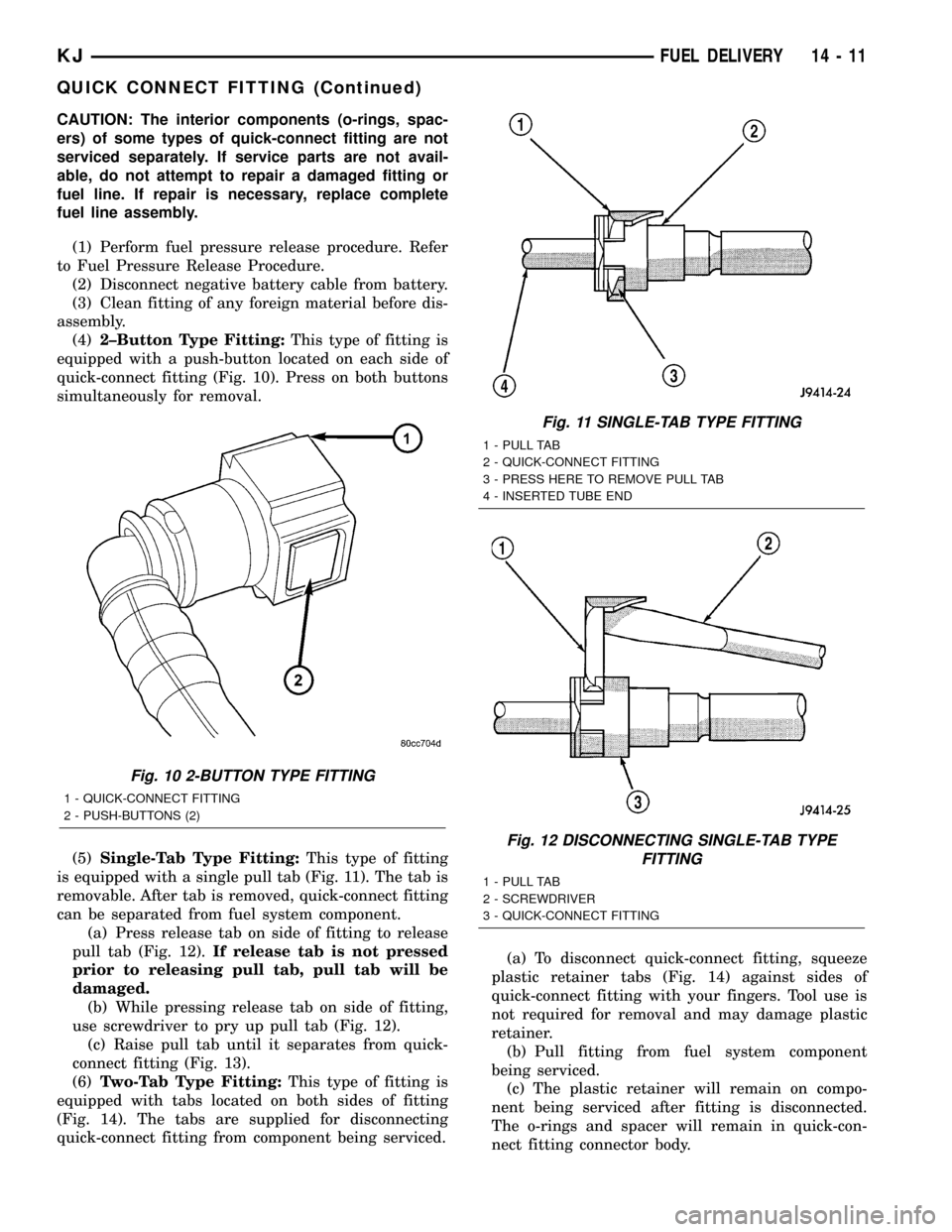
(4)2±Button Type Fitting:This type of fitting is
equipped with a push-button located on each side of
quick-connect fitting (Fig. 10). Press on both buttons
simultaneously for removal.
(5)Single-Tab Type Fitting:This type of fitting
is equipped with a single pull tab (Fig. 11). The tab is
removable. After tab is removed, quick-connect fitting
can be separated from fuel system component.
(a) Press release tab on side of fitting to release
pull tab (Fig. 12).If release tab is not pressed
prior to releasing pull tab, pull tab will be
damaged.
(b) While pressing release tab on side of fitting,
use screwdriver to pry up pull tab (Fig. 12).
(c) Raise pull tab until it separates from quick-
connect fitting (Fig. 13).
(6)Two-Tab Type Fitting:This type of fitting is
equipped with tabs located on both sides of fitting
(Fig. 14). The tabs are supplied for disconnecting
quick-connect fitting from component being serviced.(a) To disconnect quick-connect fitting, squeeze
plastic retainer tabs (Fig. 14) against sides of
quick-connect fitting with your fingers. Tool use is
not required for removal and may damage plastic
retainer.
(b) Pull fitting from fuel system component
being serviced.
(c) The plastic retainer will remain on compo-
nent being serviced after fitting is disconnected.
The o-rings and spacer will remain in quick-con-
nect fitting connector body.
Fig. 10 2-BUTTON TYPE FITTING
1 - QUICK-CONNECT FITTING
2 - PUSH-BUTTONS (2)
Fig. 11 SINGLE-TAB TYPE FITTING
1 - PULL TAB
2 - QUICK-CONNECT FITTING
3 - PRESS HERE TO REMOVE PULL TAB
4 - INSERTED TUBE END
Fig. 12 DISCONNECTING SINGLE-TAB TYPE
FITTING
1 - PULL TAB
2 - SCREWDRIVER
3 - QUICK-CONNECT FITTING
KJFUEL DELIVERY 14 - 11
QUICK CONNECT FITTING (Continued)
Page 1400 of 1803

(17) When LCS adapter test leads are attached
into relay cavities, fuel pumpwill be activated.
Determine fuel pump amperage on DRB screen.
Amperage should be below 10.0 amps. If amperage is
below 10.0 amps, and specifications for the Fuel
Pump Pressure, Fuel Pump Capacity and Fuel Pres-
sure Leak Down tests were met, the fuel pump mod-
ule is OK.
(18) If amperage is more than 10.0 amps, replace
fuel pump module assembly. The electric fuel pump
is not serviced separately.
(19) Disconnect test leads from relay cavities
immediately after testing.
FUEL PUMP MODULE
DESCRIPTION
The fuel pump module assembly is located in the
fuel tank (Fig. 1). The assembly is divided into 2±sec-
tions, upper and lower. The lower section is locked to
the bottom of the fuel tank. The complete assembly
contains the following components:
²A fuel pressure regulator
²A separate fuel pick-up, or inlet filter
²An electric fuel pump
²A lockring to retain upper section of pump mod-
ule to tank
²A rollover valve
²A vent fitting for ORVR system
²A soft gasket between tank flange and module
²A fuel gauge sending unit (fuel level sensor)
²Two fuel line connections (supply and return)
The fuel gauge sending unit may be serviced sepa-
rately. If the electrical fuel pump, primary inlet filter
or fuel pressure regulator require service, the lower
section of the fuel pump module must be replaced.
OPERATION
Refer to Fuel Pump, Inlet Filter, Fuel Pressure
Regulator and Fuel Gauge Sending Unit.
REMOVAL
The fuel pump module is divided into 2 sections,
upper and lower. To service the check (control) valve,
replace only the upper section. To service the fuel
gauge sending unit, remove the upper section. To ser-
vice the electric fuel pump, fuel pressure regulator or
primary inlet filter, remove both sections and replace
lower section.
Fuel tank removal will not be necessary for
fuel pump module removal. Access is from rear
cargo area.
(1) Four cargo holdown clamps are located inside
the vehicle on the floor of the rear cargo area.Remove the 2 rearward mounted clamps by drilling
out the clamp rivets.
(2) Fold carpeting forward to gain access to fuel
pump module access plate (Fig. 25).
(3) Remove 4 fuel pump module access plate nuts
(Fig. 25).
(4) While applying heat from a heat gun, carefully
pry up fuel pump module access plate. Take care not
to bend plate.
(5) Thoroughly clean area around top of pump
module to prevent contaminants from entering fuel
tank or fuel lines.
WARNING: THE FUEL SYSTEM IS UNDER A CON-
STANT PRESSURE EVEN WITH ENGINE OFF.
BEFORE SERVICING THE FUEL PUMP MODULE,
FUEL SYSTEM PRESSURE MUST BE RELEASED.
(6) Release fuel system pressure. Refer to Fuel
System Pressure Release procedure.
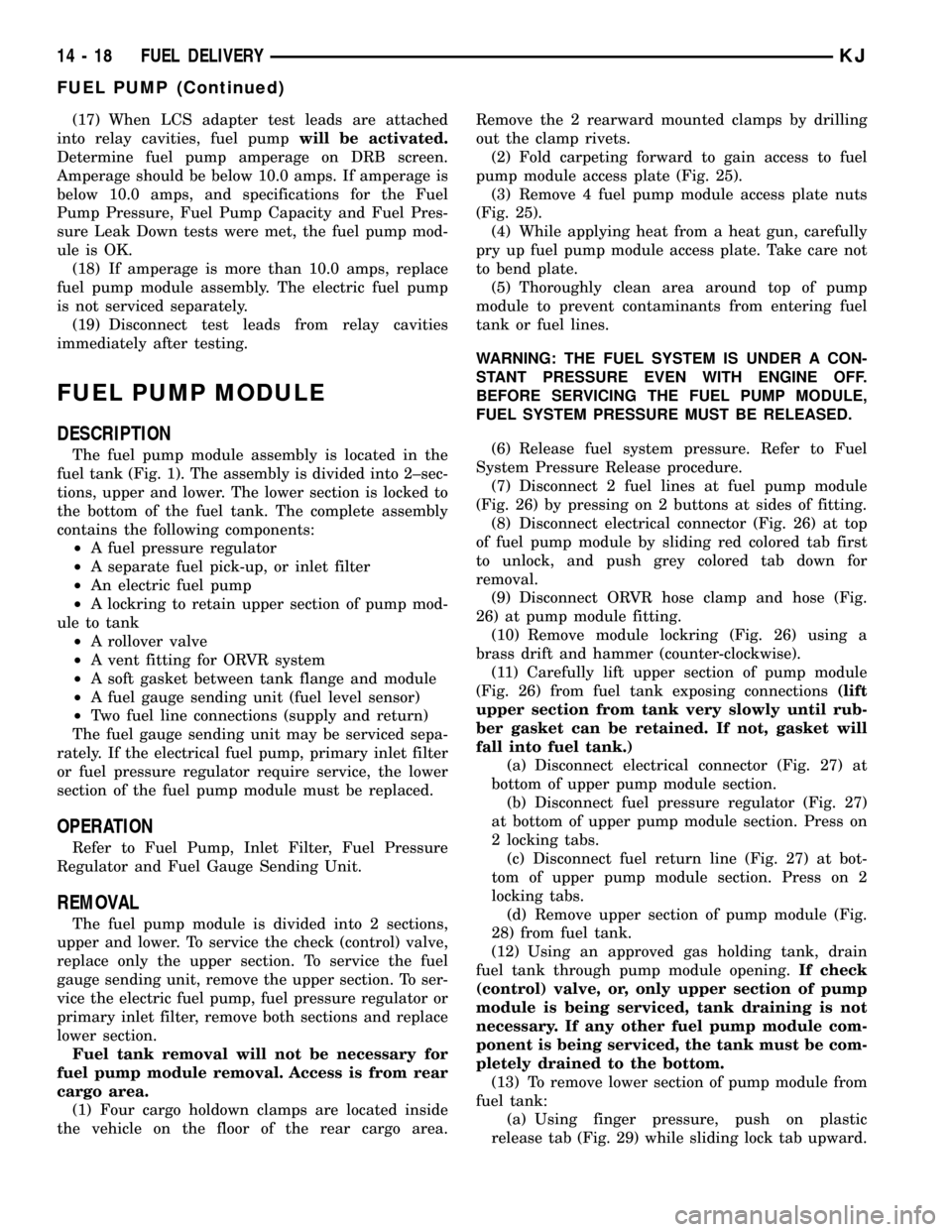
(7) Disconnect 2 fuel lines at fuel pump module
(Fig. 26) by pressing on 2 buttons at sides of fitting.
(8) Disconnect electrical connector (Fig. 26) at top
of fuel pump module by sliding red colored tab first
to unlock, and push grey colored tab down for
removal.
(9) Disconnect ORVR hose clamp and hose (Fig.
26) at pump module fitting.
(10) Remove module lockring (Fig. 26) using a
brass drift and hammer (counter-clockwise).
(11) Carefully lift upper section of pump module
(Fig. 26) from fuel tank exposing connections(lift
upper section from tank very slowly until rub-
ber gasket can be retained. If not, gasket will
fall into fuel tank.)
(a) Disconnect electrical connector (Fig. 27) at
bottom of upper pump module section.
(b) Disconnect fuel pressure regulator (Fig. 27)
at bottom of upper pump module section. Press on
2 locking tabs.
(c) Disconnect fuel return line (Fig. 27) at bot-
tom of upper pump module section. Press on 2
locking tabs.
(d) Remove upper section of pump module (Fig.
28) from fuel tank.
(12) Using an approved gas holding tank, drain
fuel tank through pump module opening.If check
(control) valve, or, only upper section of pump
module is being serviced, tank draining is not
necessary. If any other fuel pump module com-
ponent is being serviced, the tank must be com-
pletely drained to the bottom.
(13) To remove lower section of pump module from
fuel tank:
(a) Using finger pressure, push on plastic
release tab (Fig. 29) while sliding lock tab upward.
14 - 18 FUEL DELIVERYKJ
FUEL PUMP (Continued)
Page 1785 of 1803

JEEP LIBERTY 2002
23.35
60.0011.35
LeamerPassenger Sidew/ButtonLight Taupe AiL WA49TL2AASlate Gray AiL WA49XDVAAwiG ButtonLight Taupe AiL WA50TL2AASlate Gray AiL WA50XDVAADriver Sidew/Button WA49TL2AAwiG Button WA50Tl2AA9 Sleeve. HeadrestPassenger Side AiL 5066563AADriver Side AiL 5O66563AA
~21
10
5.505.50
5.505.50
5.505.50
11.9511.95
5 Holder, Cup 5072903AA6 Bezel, ConsolellLimited Model 5HK42SZ5AA.1Sport Model 5GP21 DX9AB .1lIAdditional Parts &lor Dealer Contact Required7 Bin, StorageSlate Gray 5GP34XDVABTaupe 5GP34WL8AB8 Bezel, SwitchFrontSlate Gray WA63XDVAATaupe WA63WL8AARearSlate Gray WA64XDVAATaupe WA64WL8AA9 Switch, Power WindowFront 56010090AC10 Cover, Console 5GG16DX9AB11 Cover, Rear Console::ilate Gray 5GP35XDVABTaupe 5GP35WL8AB.12 Switch, Power Window~ear 56010091AB_.
6.606.60
1 22.10I 22.10
1 22.101 22.10
1 0.001 11.85
1 11.101 11.10!-, 27.85f-5
14
, 10
~A
14~
LeatherPassenger SideLight TaupeSlate GrayDriver SideLight TaupeSlate Gray
UZ401 L2AAUZ401DVAA
UZ401L2AAUZ401DVAA
#.8 577.00#.8 577.00
#.8 577.00#.8 577.00
15
1':J
20
1~
.,-'i
Use Procedure Explanations 14,15 and 28 with the fol/owingtext.
Heated ---
Passenger SideUgh! Taupe UZ381L2AA 1.8 932.00Slate Gray UZ381DVAA #.8 932.00Driver SideUgh! Taupe UZ391L2AA #.8 932.00Slate Gray UZ391DVAA #.8 932.001Non-HeatedPassenger SideUght Taupe UZ361 L2AA 1.8 864.00Slate Gray UZ361DVAA 1.8 864.00Driver SideUght Taupe UZ371L2AA #.8 864.00Slate Gray UZ371DVAA 1.8 864.00#R&R One Side Complete, wISest Assy Removed3 Cover, Seat CushionClothPassenger SideISlate Gray UZ161DVAA Tau~ UZ161L5AA
Driver SideSlate Gray UZ171DVAAraupe UZ171L5AALeatherHeatedPassenger SideUgh! Taupe UZ201L2AASlate Gray UZ201DVAADriver SideUght Taupe UZ211 L2AASlate Gray UZ211DVAANon-HeatedPassenger SideUghtTaupe UZ181L2AASlate Gray UZ181DVAADriver SideLight Taupe UZ191L2AASlate Gray UZ191DVAA 4 Frame, Seat Cushionll
ManualPassenger Side 5072110AADriver Side 5072111AAPowerPassenger Side 5O72126AADriver Side 5072126AA1]Additional Palts &Jar Dealer Contact Required ~5 Heater, Seat Back .c
Passenger Side 5072368AADriver Side 5072368AA6 Heater, Seat CushionPassenger Side 5072369AAIDriver Side 5072369AA7 HeadrestClothPassen er SideSlate ~ray WB351DVAATaupe WB351L5AADriver SideSlate Gray WB351DVA.A.Taupe WB351L5AALeatherPassenger SideUght Taupe WA521L2AASlate Gray WA521DVAADriver SideLight Taupe WA521L2AASlate Gray WA521DVAA.. ..8 Cap, HeadrestClothPassenger Sidew/ButtonSlate GrayTaupeIwlo ButtonSlate Gray\raupe Driver Side
w/Buttonwlo Button
ROCKER/PILLARS
1
17--
g~285.00285.00
287.00287.00
004-09545
1 Panel, Outer Side Body Repair-See Side Body Section
FLOOR
1
16.3516.35
15.3515.35
""
~~6492.00350.00
495.003SQOO19.3513.3519.3513~~.,
~
),
144.00 I144.00
136.00136.00
20.5013.3521.70
13.35
13.3520.5013.3521.70
83.6083.6083.6083.60
65
87.9587.95
112.0011200
004-09546
1 Pan Assy, Front Floor 55176800AB #18.0 459.00#W/Each Front Frame Rail Removed Deduct 3.5, w/EachSide Body Si// Removed Deduct 2.02 Bracket, Floor1] 55360352AB 1.0 14.853 Crossmember, Front Seal1l R/L 55360058AA 1.5 23.954 Crossmember, Rear Seat1] 55360060AB 2.0 36.001]lncluded w/Front Floor Pan Assy5 Crossmember, Trans-See Englne/Trans Mounts Section6 Sill, Side Body R 55176878AA s 4.0 0.00L 55176879AA s 4.0 0.0012.7012.70
12.7012~0
.1 86.70.1 153.00
.1 86.701 15300LIMITED MODEL
R&I Seat AssyR/L.3
Illustration Located in Next Column5.505.50
5.505.50
5.505.50
AIL WA49XDVAAAIL WA49WL5AA
AIL WA50XDVAAAIL WASOWL5AA
AIL WA49WL5AAAIL WA50WL5AA
Seat Back
#.8 327.00#.8 327.00
#.8 327.00#.8 327.00
UZ311DVAAUZ311L5AA
UZ311DVAAUZ311L5AA
12.7012.70
12.7012.70
4.604.60
CH
3'(
~004-09547
SJt79-1 -S
2[;'
~C
~6
1.)
004-09548 "'i'-16
Adjuster, Seat Track10 ManualPassenger Side R 5072104AA #.5 97.10L 5072105AA #.5 123.00#R&R Both Sides .8, wISest Assy RemovedDriver Side R SO72107M #.5 97.10L 5072106AA #.5 t23.00#R&R Both Sides .8, wISest Assy RemovedI PowerPassenger Side WD24WL8AA #.4 799.00582.00 Driver Side WD25XDVAA #.4 799.00582.00I#WlSeat Assy Removed12 Handle, AdJuster585.00 Passenger Side 5072003AA ;,...;,---585.00 Dnver Side 5072003AA .;113 Cable, Recliner C
Passenger Side 5066458AADriver Side 5066458AA114 Shield, Adjuste~Manual ,Passenger Side R UZSOWL5AA .1L UZ42TL2AA .1Driver Side R UZ51WL5AA .1L UZ43TL2AA .1 ,---PowerPassenger SideHeatec R UZ541L2AA .1L UZ42TL2AA .1Non-Heated R UZ52TL2AA .1L UZ43TL2AA .1Driver SideHeated R UZ43TL2AA .1L UZ551L2AA .1Non-Heated R UZ43TL2AA .1L UZ53WL5AA .1,15 Recliner, Seat11; Passenger Side R 5072020AAL 5072021AADriver Side R SO72022AA.1 157.00 L 5072023AA.1 157.00IllAdditional Parts &/or Dealer Contact Required16 HandletRecliner.1 157.00 Light aupe.1 157.00 Passenger SideTo 6-1-01 UZ281L2AAFrom 6-1-01 UZ281L2ABDriver SideTo 6-1-01 UZ291L2AAFrom 6-1-01 UZ291L2AB -'./Slate Grav