2002 JEEP LIBERTY Rear lower control arm
[x] Cancel search: Rear lower control armPage 41 of 1803

INSTALLATION
(1) Position the upper suspension arm in the
frame rail brackets (Fig. 8).
(2) Install the mounting bolts and tighten to 100
N´m (74 ft. lbs.).
(3) Retighten the heat shield back into place.
(4) Pull the arm down on the differential housing
bracket and install the pinch bolt and nut. Tighten
the nut to 95 N´m (70 ft. lbs.) (Fig. 7).
(5) Remove the supports and lower the vehicle.
LOWER CONTROL ARM
DESCRIPTION
The lower suspension arms are stamped steel and
welded and use voided round bushings at the axle
end and solid rubber at the body end of the arm.
OPERATION
The bushings provide isolation from the axle. The
arms mount to the unibody frame rail bracket and
the axle brackets. The arm and bushings provide
location and react to loads.
REMOVAL
(1) Raise the vehicle and support the rear axle.
(2) Remove the stabilizer bar retaining bolts from
the suspension arm.
(3) Remove the lower suspension arm nut and bolt
from the axle bracket (Fig. 10).
NOTE: When removing the right side suspension
arm from the frame rail it will be necessary to pry
the exhaust over slightly to allow enough clearance
to remove the bolt.
(4) Remove the nut and bolt (Fig. 10) from the
frame rail and remove the lower suspension arm.
INSTALLATION
(1) Position the lower suspension arm in the axle
bracket and frame rail bracket.NOTE: The end of the arm with the voided round
bushing attaches to the axle bracket.
(2) Install the axle bracket bolt and nut finger
tight (Fig. 10).
NOTE: When installing the right side suspension
arm to the frame rail it will be necessary to pry the
exhaust over slightly to allow enough clearance to
install the bolt.
(3) Install the frame rail bracket bolt and nut fin-
ger tight.
(4) Install the stabilizer bar retaining bolts to the
suspension arm.
(5) Remove the supports and lower the vehicle.
(6) With the vehicle on the ground tighten the nut
at the frame to 163 N´m (120 ft. lbs.). Tighten the
nut at the axle bracket to 163 N´m (120 ft. lbs.).
Fig. 10 LOWER SUSPENSION ARM
1 - AXLE BRACKET BOLT
2 - LOWER CONTROL ARM
3 - BODY BRACKET BOLT
KJREAR 2 - 21
UPPER CONTROL ARM (Continued)
Page 42 of 1803

SUSPENSION
TABLE OF CONTENTS
page page
FRONT
SPECIAL TOOLS
FRONT SUSPENSION...................1
BUSHINGS
REMOVAL
REMOVAL - LOWER CONTROL ARM
BUSHING............................2
REMOVAL - CLEVIS BRACKET BUSHING....2
REMOVAL - UPPER CONTROL ARM
BUSHINGS...........................3
INSTALLATION
INSTALLATION - LOWER CONTROL ARM
BUSHING............................3
INSTALLATION - CLEVIS BRACKET
BUSHING............................4
INSTALLATION - UPPER CONTROL ARM
BUSHINGS...........................4
LOWER BALL JOINT
REMOVAL.............................5INSTALLATION..........................5
REAR
SPECIAL TOOLS
REAR SUSPENSION....................6
UPPER BALL JOINT
REMOVAL.............................6
INSTALLATION..........................6
BUSHINGS
REMOVAL
REMOVAL - LOWER SUSPENSION ARM
BUSHING............................7
REMOVAL - UPPER SUSPENSION ARM
BUSHING............................7
INSTALLATION
INSTALLATION - LOWER SUSPENSION
ARM BUSHING........................8
INSTALLATION - UPPER SUSPENSION ARM
BUSHING............................8
FRONT
SPECIAL TOOLS
FRONT SUSPENSION
BALL JOINT PRESS - C-4212F
Remover C-4150A
REMOVER / INSTALLER FRONT LOWER BALL
JOINT - 8859
KJSUSPENSION 2s - 1
Page 43 of 1803
BUSHINGS
REMOVAL
REMOVAL - LOWER CONTROL ARM BUSHING
(1) Remove the lower control arm (Refer to 2 -
SUSPENSION/FRONT/LOWER CONTROL ARM -
REMOVAL).
(2) Secure the control arm in a vise.
NOTE: Extreme pressure lubrication must be used
on the threaded portions of the tool. This will
increase the longevity of the tool and insure proper
operation during the removal and installation pro-
cess.
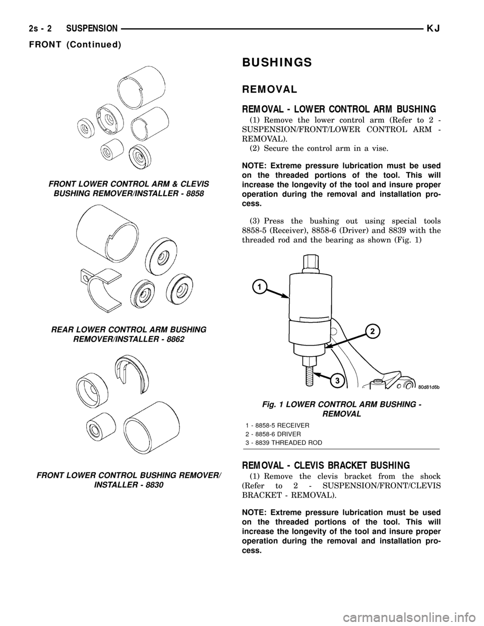
(3) Press the bushing out using special tools
8858-5 (Receiver), 8858-6 (Driver) and 8839 with the
threaded rod and the bearing as shown (Fig. 1)
REMOVAL - CLEVIS BRACKET BUSHING
(1) Remove the clevis bracket from the shock
(Refer to 2 - SUSPENSION/FRONT/CLEVIS
BRACKET - REMOVAL).
NOTE: Extreme pressure lubrication must be used
on the threaded portions of the tool. This will
increase the longevity of the tool and insure proper
operation during the removal and installation pro-
cess.
FRONT LOWER CONTROL ARM & CLEVIS
BUSHING REMOVER/INSTALLER - 8858
REAR LOWER CONTROL ARM BUSHING
REMOVER/INSTALLER - 8862
FRONT LOWER CONTROL BUSHING REMOVER/
INSTALLER - 8830
Fig. 1 LOWER CONTROL ARM BUSHING -
REMOVAL
1 - 8858-5 RECEIVER
2 - 8858-6 DRIVER
3 - 8839 THREADED ROD
2s - 2 SUSPENSIONKJ
FRONT (Continued)
Page 48 of 1803

(2) Press the ball joint in the upper suspension
arm.
(3) Remove the upper suspension arm from the
vise.
(4) Reinstall the upper suspension arm (Refer to 2
- SUSPENSION/REAR/UPPER CONTROL ARM -
INSTALLATION).
(5) Raise the rear axle with a hydraulic jack to
align the ball joint with the differential housing
bracket.
(6) Insert the ball joint into the differential hous-
ing bracket.
(7) Install the ball joint pinch bolt and tighten to
95 N´m (70 ft. lbs.). (Fig. 9).
(8) Remove the supports and lower the vehicle.
BUSHINGS
REMOVAL
REMOVAL - LOWER SUSPENSION ARM
BUSHING
(1) Remove the lower suspension arm (Refer to 2 -
SUSPENSION/REAR/LOWER CONTROL ARM -
REMOVAL).
(2) Secure the suspension arm in a vise.
NOTE: Extreme pressure lubrication must be used
on the threaded portions of the tool. This will
increase the longevity of the tool and insure proper
operation during the removal and installation pro-
cess.(3) Install special tools 8862-4 (receiver), 8862-5
(spacer) and 8862-1 or 8862- 2 (driver) with the
threaded rod 8839 and the bearing as shown (Fig. 12)
(4) Press out the bushing.
REMOVAL - UPPER SUSPENSION ARM
BUSHING
(1) Remove the upper suspension arm (Refer to 2 -
SUSPENSION/REAR/UPPER CONTROL ARM -
REMOVAL).
(2) Secure the suspension arm in a vise.
NOTE: Extreme pressure lubrication must be used
on the threaded portions of the tool. This will
increase the longevity of the tool and insure proper
operation during the removal and installation pro-
cess.
(3) Install special tools 8853-3 (driver), 8860-1
(receiver) and with the threaded rod 8838 and the
bearing as shown (Fig. 13)
(4) Press out the bushing.
Fig. 11 UPPER BALL JOINT - INSTALLATION
1 - C-4212F PRESS
2 - 8861-1 RECEIVER
3 - 8861-2 DRIVER
Fig. 12 LOWER SUSPENSION ARM BUSHING
REMOVAL
1 - 8839 THREADED ROD
2 - 8862-4 RECEIVER
3 - 8862-5 SPACER
4 - 8862-1 OR 8862-2 DRIVERS
KJSUSPENSION 2s - 7
UPPER BALL JOINT (Continued)
Page 49 of 1803

INSTALLATION
INSTALLATION - LOWER SUSPENSION ARM
BUSHING
NOTE: Extreme pressure lubrication must be used
on the threaded portions of the tool. This will
increase the longevity of the tool and insure proper
operation during the removal and installation pro-
cess.
(1) Install the new lower suspension arm bushings
into the lower suspension arm using tools 8862-3
(driver), 8862-4 (receiver), 8862-5 (spacer) and the
bearing with the threaded rod 8839 (Fig. 14) making
sure to properly orient the bushing in the suspension
arm.
(2) Remove the suspension arm from the vise.
(3) Install the lower suspension arm (Refer to 2 -
SUSPENSION/REAR/LOWER CONTROL ARM -
INSTALLATION).
INSTALLATION - UPPER SUSPENSION ARM
BUSHING
NOTE: Extreme pressure lubrication must be used
on the threaded portions of the tool. This will
increase the longevity of the tool and insure proper
operation during the removal and installation pro-
cess.
(1) Install the new upper suspension arm bushings
into the upper suspension arm using tools 8835-3(receiver), 8860-2 (driver) and the bearing with the
threaded rod 8838 (Fig. 15) making sure to properly
orient the bushing in the suspension arm.
(2) Remove the suspension arm from the vise.
(3) Install the upper suspension arm (Refer to 2 -
SUSPENSION/REAR/UPPER CONTROL ARM -
INSTALLATION).
Fig. 13 UPPER SUSPENSION ARM BUSHING -
REMOVAL
1 - 8853-3 DRIVER
2 - 8860-1 RECEIVER
3 - 8838 THREADED ROD
Fig. 14 LOWER SUSPENSION ARM BUSHING
INSTALLATION
1 - 8862-3 DRIVER
2 - 8862-5 SPACER
3 - 8862-4 RECEIVER
4 - 8839 THREADED ROD
Fig. 15 UPPER SUSPENSION ARM BUSHING -
INSTALLATION
1 - 8838 THREADED ROD
2 - 8835-3 RECEIVER
3 - 8860-2 DRIVER
2s - 8 SUSPENSIONKJ
BUSHINGS (Continued)
Page 60 of 1803

(5) Remove lower clevis bolt (Fig. 2).
(6) Seperate lower ball joint from the lower control
arm (Fig. 3).
(7) Pull out on the steering knuckle and push the
half shaft out of the knuckle.
(8) With a pry bar remove the half shaft from the
axle.
NOTE: The right side has a splined axle shaft that
will stay in the axle.
INSTALLATION
(1) Apply a light coat of wheel bearing grease on
the female splines of the inner C/V joint.(2) Install half shaft on the axle shaft spline and
push firmly to engage the snap ring. Pull on the half
shaft to verify snap has engaged.
(3) Clean hub bearing bore and apply a light coat
of wheel bearing grease.
(4) Pull out on the steering knuckle and push the
half shaft through the knuckle.
(5) Install lower ball joint into the lower control
arm and tighten pinch bolt.
(6) Align clevis with knuckle. Install and tighten
lower clevis bolt.
(7) Install stabilizer link.
(8) Install half shaft hub nut.
(9) Install wheel and tire assembly.
(10) Remove support and lower vehicle.
SPECIFICATIONS
HALF SHAFT
TORQUE SPECIFICATIONS
DESCRIPTION N´m Ft. Lbs. In. Lbs.
Half Shaft Nut 136 100 -
Fig. 3 LOWER CONTROL ARM
1 - FRONT CAM BOLT
2 - OUTER TIE ROD END
3 - LOWER BALL JOINT NUT
4 - LOWER CONTROL ARM
5 - REAR CAM BOLTFig. 2 CLEVIS BRACKET
1 - UPPER BOLT
2 - CLEVIS BRACKET
3 - LOWER BOLT
KJHALF SHAFT 3 - 11
HALF SHAFT (Continued)
Page 73 of 1803

REMOVAL
(1) Raise and support vehicle.
(2) Remove wheel and tire assemblies.
(3) Remove half shaft hub nuts.
(4) Remove lower control arms. Refer to 2 suspen-
sion for procedure.
(5) Remove half shafts.
(6) Remove skid plate.
(7) Remove differential drain plug (Fig. 3) and
drain fluid.
(8) Remove differential vent hose (Fig. 4) from
cover.
(9) Remove propeller shaft from pinion flange.
(10) Support axle with a lift/jack.
(11) Remove bolt from left front axle bracket frame
mount (Fig. 5).
(12) Remove bolts from right axle bracket frame
mounts (Fig. 6).
(13) Remove bolt from left rear axle bracket frame
mount (Fig. 7).
(14) Lower axle from vehicle.
(15) Remove brackets from axle if necessary.
INSTALLATION
(1) Install left rear bracket to axle and tighten to
61 N´m (45 ft. lbs.).
(2) Install right bracket to axle and tighten to 88
N´m (65 ft. lbs.).(3) Install left front bracket to axle and tighten to
61 N´m (45 ft. lbs.).
(4) Raise axle up and align brackets with frame
mounts.
(5) Install frame mount bolts and tighten to 88
N´m (65 ft. lbs.).
(6) Install propeller shaft.
(7) Install half shafts.
Fig. 3 DRAIN PLUG
1 - LEFT FRONT AXLE BRACKET
2 - DRAIN PLUG
3 - DIFFERENTIAL HOUSING
Fig. 4 DIFFERENTIAL COVER
1 - COVER
2 - VENT TUBE
Fig. 5 LEFT FRONT AXLE BRACKET
1 - LEFT FRONT AXLE BRACKET
2 - BRACKET BOLT
3 - 24 FRONT AXLE - 186FIAKJ
FRONT AXLE - 186FIA (Continued)
Page 74 of 1803

(8) Install lower control arms, refer to 2 Suspen-
sion for procedures.
(9) Install new half shaft hub nuts and tighten to
136 N´m (100 ft. lbs.).
(10) Install axle vent hose.
(11) Fill differential with gear lubricant.
(12) Install skid plate.
(13) Install wheel and tire assemblies.
(14) Remove support and lower vehicle.
(15) Check vehicle alignment.
ADJUSTMENTS
Ring and pinion gears are supplied as matched
sets only. The identifying numbers for the ring and
pinion gear are etched onto each gear (Fig. 8). A plus
(+) number, minus (±) number or zero (0) is etched
into the face of the pinion gear. This number is the
amount (in thousandths of an inch) the depth varies
from the standard depth setting of a pinion etched
with a (0). The standard setting from the center line
of the ring gear to the back face of the pinion is 92.1
mm (3.625 in.). The standard depth provides the best
gear tooth contact pattern. Refer to Backlash and
Contact Pattern Analysis paragraph in this section
for additional information.
Fig. 6 RIGHT AXLE BRACKET
1 - RIGHT AXLE BRACKET
2 - FRONT BRACKET BOLT
3 - REAR BRACKET BOLT
Fig. 7 LEFT REAR AXLE BRACKET
1 - LEFT REAR AXLE BRACKET
2 - BRACKET BOLT
Fig. 8 PINION GEAR ID NUMBERS
1 - PRODUCTION NUMBERS
2 - DRIVE PINION GEAR DEPTH VARIANCE
3 - GEAR MATCHING NUMBER
KJFRONT AXLE - 186FIA 3 - 25
FRONT AXLE - 186FIA (Continued)