2002 JEEP LIBERTY high intake temp
[x] Cancel search: high intake tempPage 235 of 1803

The ECT sensor is a two-wire Negative Thermal
Coefficient (NTC) sensor. Meaning, as engine coolant
temperature increases, resistance (voltage) in the
sensor decreases. As temperature decreases, resis-
tance (voltage) in the sensor increases.
OPERATION
At key-on, the Powertrain Control Module (PCM)
sends out a regulated 5 volt signal to the ECT sensor.
The PCM then monitors the signal as it passes
through the ECT sensor to the sensor ground (sensor
return).
When the engine is cold, the PCM will operate in
Open Loop cycle. It will demand slightly richer air-
fuel mixtures and higher idle speeds. This is done
until normal operating temperatures are reached.
The PCM uses inputs from the ECT sensor for the
following calculations:
²for engine coolant temperature gauge operation
through CCD or PCI (J1850) communications
²Injector pulse-width
²Spark-advance curves
²ASD relay shut-down times
²Idle Air Control (IAC) motor key-on steps
²Pulse-width prime-shot during cranking
²O2 sensor closed loop times
²Purge solenoid on/off times
²EGR solenoid on/off times (if equipped)
²Leak Detection Pump operation (if equipped)
²Radiator fan relay on/off times (if equipped)
²Target idle speed
REMOVAL
2.4L
The Engine Coolant Temperature (ECT) sensor is
installed into a water jacket at left front of cylinder
head (Fig. 1).
WARNING: HOT, PRESSURIZED COOLANT CAN
CAUSE INJURY BY SCALDING. COOLING SYSTEM
MUST BE PARTIALLY DRAINED BEFORE REMOV-
ING THE COOLANT TEMPERATURE SENSOR.
(1) Partially drain cooling system.
(2) Disconnect electrical connector from sensor.
(3) Remove sensor from cylinder head.
3.7L
The Engine Coolant Temperature (ECT) sensor is
installed into a water jacket at front of intake mani-
fold near rear of generator (Fig. 2).
WARNING: HOT, PRESSURIZED COOLANT CAN
CAUSE INJURY BY SCALDING. COOLING SYSTEM
MUST BE PARTIALLY DRAINED BEFORE REMOV-
ING THE COOLANT TEMPERATURE SENSOR.(1) Partially drain cooling system.
(2) Disconnect electrical connector from sensor.
(3) Remove sensor from intake manifold.
Fig. 1 ECT AND UPPER TIMING BELT COVER/
BOLTS-2.4L
1 - UPPER TIMING BELT COVER
2 - ELECTRICAL CONNECTOR (ECT)
3 - MOUNTING BOLTS (3)
Fig. 2 MAP SENSOR / ECT SENSOR - 3.7L
1 - MOUNTING SCREWS
2 - MAP SENSOR
3 - ECT SENSOR
7 - 20 ENGINEKJ
ENGINE COOLANT TEMPERATURE SENSOR (Continued)
Page 268 of 1803

ENGINE COOLANT
TEMPERATURE SENSOR
DESCRIPTION
The Engine Coolant Temperature (ECT) sensor is
used to sense engine coolant temperature. The sensor
protrudes into an engine water jacket.
The ECT sensor is a two-wire Negative Thermal
Coefficient (NTC) sensor. Meaning, as engine coolant
temperature increases, resistance (voltage) in the
sensor decreases. As temperature decreases, resis-
tance (voltage) in the sensor increases.
OPERATION
At key-on, the Powertrain Control Module (PCM)
sends out a regulated 5 volt signal to the ECT sensor.
The PCM then monitors the signal as it passes
through the ECT sensor to the sensor ground (sensor
return).
When the engine is cold, the PCM will operate in
Open Loop cycle. It will demand slightly richer air-
fuel mixtures and higher idle speeds. This is done
until normal operating temperatures are reached.
The PCM uses inputs from the ECT sensor for the
following calculations:
²for engine coolant temperature gauge operation
through CCD or PCI (J1850) communications
²Injector pulse-width²Spark-advance curves
²ASD relay shut-down times
²Idle Air Control (IAC) motor key-on steps
²Pulse-width prime-shot during cranking
²O2 sensor closed loop times
²Purge solenoid on/off times
²EGR solenoid on/off times (if equipped)
²Leak Detection Pump operation (if equipped)
²Radiator fan relay on/off times (if equipped)
²Target idle speed
REMOVAL
2.4L
The Engine Coolant Temperature (ECT) sensor is
installed into a water jacket at left front of cylinder
head (Fig. 2).
WARNING: HOT, PRESSURIZED COOLANT CAN
CAUSE INJURY BY SCALDING. COOLING SYSTEM
MUST BE PARTIALLY DRAINED BEFORE REMOV-
ING THE COOLANT TEMPERATURE SENSOR.
(1) Partially drain cooling system.
(2) Disconnect electrical connector from sensor.
(3) Remove sensor from cylinder head.
3.7L
The Engine Coolant Temperature (ECT) sensor is
installed into a water jacket at front of intake mani-
fold near rear of generator (Fig. 3).
Fig. 1 ENGINE BLOCK HEATER 2.4L
1 - CORE HOLE
2 - BLOCK HEATER
3 - POWER CORD
Fig. 2 ECT AND UPPER TIMING BELT COVER/
BOLTS-2.4L
1 - UPPER TIMING BELT COVER
2 - ELECTRICAL CONNECTOR (ECT)
3 - MOUNTING BOLTS (3)
KJENGINE7s-21
ENGINE BLOCK HEATER - 2.4L (Continued)
Page 311 of 1803

²The fuel pump is energized through the fuel
pump relay by the PCM. The fuel pump will operate
for approximately three seconds unless the engine is
operating or the starter motor is engaged.
²The O2S sensor heater element is energized via
the ASD or O2S heater relay. The O2S sensor input
is not used by the PCM to calibrate air-fuel ratio dur-
ing this mode of operation.
ENGINE START-UP MODE
This is an Open Loop mode. The following actions
occur when the starter motor is engaged.
The PCM receives inputs from:
²Battery voltage
²Engine coolant temperature sensor
²Crankshaft position sensor
²Intake manifold air temperature sensor
²Manifold absolute pressure (MAP) sensor
²Throttle position sensor (TPS)
²Camshaft position sensor signal
The PCM monitors the crankshaft position sensor.
If the PCM does not receive a crankshaft position
sensor signal within 3 seconds of cranking the
engine, it will shut down the fuel injection system.
The fuel pump is activated by the PCM through
the fuel pump relay.
Voltage is applied to the fuel injectors with the
ASD relay via the PCM. The PCM will then control
the injection sequence and injector pulse width by
turning the ground circuit to each individual injector
on and off.
The PCM determines the proper ignition timing
according to input received from the crankshaft posi-
tion sensor.
ENGINE WARM-UP MODE
This is an Open Loop mode. During engine warm-
up, the PCM receives inputs from:
²Battery voltage
²Crankshaft position sensor
²Engine coolant temperature sensor
²Intake manifold air temperature sensor
²Manifold absolute pressure (MAP) sensor
²Throttle position sensor (TPS)
²Camshaft position sensor signal
²Park/neutral switch (gear indicator signalÐauto.
trans. only)
²Air conditioning select signal (if equipped)
²Air conditioning request signal (if equipped)
Based on these inputs the following occurs:
²Voltage is applied to the fuel injectors with the
ASD relay via the PCM. The PCM will then control
the injection sequence and injector pulse width by
turning the ground circuit to each individual injector
on and off.²The PCM adjusts engine idle speed through the
idle air control (IAC) motor and adjusts ignition tim-
ing.
²The PCM operates the A/C compressor clutch
through the A/C compressor clutch relay. This is done
if A/C has been selected by the vehicle operator and
specified pressures are met at the high and low±pres-
sure A/C switches. Refer to Heating and Air Condi-
tioning for additional information.
²When engine has reached operating tempera-
ture, the PCM will begin monitoring O2S sensor
input. The system will then leave the warm-up mode
and go into closed loop operation.
IDLE MODE
When the engine is at operating temperature, this
is a Closed Loop mode. At idle speed, the PCM
receives inputs from:
²Air conditioning select signal (if equipped)
²Air conditioning request signal (if equipped)
²Battery voltage
²Crankshaft position sensor
²Engine coolant temperature sensor
²Intake manifold air temperature sensor
²Manifold absolute pressure (MAP) sensor
²Throttle position sensor (TPS)
²Camshaft position sensor signal
²Battery voltage
²Park/neutral switch (gear indicator signalÐauto.
trans. only)
²Oxygen sensors
Based on these inputs, the following occurs:
²Voltage is applied to the fuel injectors with the
ASD relay via the PCM. The PCM will then control
injection sequence and injector pulse width by turn-
ing the ground circuit to each individual injector on
and off.
²The PCM monitors the O2S sensor input and
adjusts air-fuel ratio by varying injector pulse width.
It also adjusts engine idle speed through the idle air
control (IAC) motor.
²The PCM adjusts ignition timing by increasing
and decreasing spark advance.
²The PCM operates the A/C compressor clutch
through the A/C compressor clutch relay. This is done
if A/C has been selected by the vehicle operator and
specified pressures are met at the high and low±pres-
sure A/C switches. Refer to Heating and Air Condi-
tioning for additional information.
CRUISE MODE
When the engine is at operating temperature, this
is a Closed Loop mode. At cruising speed, the PCM
receives inputs from:
²Air conditioning select signal (if equipped)
²Air conditioning request signal (if equipped)
8E - 12 ELECTRONIC CONTROL MODULESKJ
POWERTRAIN CONTROL MODULE (Continued)
Page 312 of 1803

²Battery voltage
²Engine coolant temperature sensor
²Crankshaft position sensor
²Intake manifold air temperature sensor
²Manifold absolute pressure (MAP) sensor
²Throttle position sensor (TPS)
²Camshaft position sensor signal
²Park/neutral switch (gear indicator signalÐauto.
trans. only)
²Oxygen (O2S) sensors
Based on these inputs, the following occurs:
²Voltage is applied to the fuel injectors with the
ASD relay via the PCM. The PCM will then adjust
the injector pulse width by turning the ground circuit
to each individual injector on and off.
²The PCM monitors the O2S sensor input and
adjusts air-fuel ratio. It also adjusts engine idle
speed through the idle air control (IAC) motor.
²The PCM adjusts ignition timing by turning the
ground path to the coil(s) on and off.
²The PCM operates the A/C compressor clutch
through the clutch relay. This happens if A/C has
been selected by the vehicle operator and requested
by the A/C thermostat.
ACCELERATION MODE
This is an Open Loop mode. The PCM recognizes
an abrupt increase in throttle position or MAP pres-
sure as a demand for increased engine output and
vehicle acceleration. The PCM increases injector
pulse width in response to increased throttle opening.
DECELERATION MODE
When the engine is at operating temperature, this
is an Open Loop mode. During hard deceleration, the
PCM receives the following inputs.
²Air conditioning select signal (if equipped)
²Air conditioning request signal (if equipped)
²Battery voltage
²Engine coolant temperature sensor
²Crankshaft position sensor
²Intake manifold air temperature sensor
²Manifold absolute pressure (MAP) sensor
²Throttle position sensor (TPS)
²Camshaft position sensor signal
²Park/neutral switch (gear indicator signalÐauto.
trans. only)
²Vehicle speed
If the vehicle is under hard deceleration with the
proper rpm and closed throttle conditions, the PCM
will ignore the oxygen sensor input signal. The PCM
will enter a fuel cut-off strategy in which it will not
supply a ground to the injectors. If a hard decelera-
tion does not exist, the PCM will determine the
proper injector pulse width and continue injection.Based on the above inputs, the PCM will adjust
engine idle speed through the idle air control (IAC)
motor.
The PCM adjusts ignition timing by turning the
ground path to the coil on and off.
WIDE OPEN THROTTLE MODE
This is an Open Loop mode. During wide open
throttle operation, the PCM receives the following
inputs.
²Battery voltage
²Crankshaft position sensor
²Engine coolant temperature sensor
²Intake manifold air temperature sensor
²Manifold absolute pressure (MAP) sensor
²Throttle position sensor (TPS)
²Camshaft position sensor signal
During wide open throttle conditions, the following
occurs:
²Voltage is applied to the fuel injectors with the
ASD relay via the PCM. The PCM will then control
the injection sequence and injector pulse width by
turning the ground circuit to each individual injector
on and off. The PCM ignores the oxygen sensor input
signal and provides a predetermined amount of addi-
tional fuel. This is done by adjusting injector pulse
width.
²The PCM adjusts ignition timing by turning the
ground path to the coil(s) on and off.
IGNITION SWITCH OFF MODE
When ignition switch is turned to OFF position,
the PCM stops operating the injectors, ignition coil,
ASD relay and fuel pump relay.
DESCRIPTION - 5 VOLT SUPPLIES
Two different Powertrain Control Module (PCM)
five volt supply circuits are used; primary and sec-
ondary.
DESCRIPTION - IGNITION CIRCUIT SENSE
This circuit ties the ignition switch to the Power-
train Control Module (PCM).
DESCRIPTION - POWER GROUNDS
The Powertrain Control Module (PCM) has 2 main
grounds. Both of these grounds are referred to as
power grounds. All of the high-current, noisy, electri-
cal devices are connected to these grounds as well as
all of the sensor returns. The sensor return comes
into the sensor return circuit, passes through noise
suppression, and is then connected to the power
ground.
The power ground is used to control ground cir-
cuits for the following PCM loads:
²Generator field winding
KJELECTRONIC CONTROL MODULES 8E - 13
POWERTRAIN CONTROL MODULE (Continued)
Page 762 of 1803

8W-02 COMPONENT INDEX
Component Page
A/C Compressor Clutch Relay........... 8Wa-42
A/C Compressor Clutch................ 8Wa-42
A/C-Heater Control................... 8Wa-42
A/C High Pressure Switch.............. 8Wa-42
A/C Low Pressure Switch............... 8Wa-42
A/C Pressure Transducer............... 8Wa-42
Accelerator Pedal Position Sensor........ 8Wa-30
Airbag Control Module................. 8Wa-43
Ambient Temperature Sensor............ 8Wa-45
Antenna Module...................... 8Wa-47
Antenna............................ 8Wa-47
Ash Receiver Lamp................... 8Wa-44
Auto Shut Down Relay................. 8Wa-30
Back-Up Lamp Switch................. 8Wa-31
Battery Temperature Sensor......... 8Wa-20, 30
Battery............................. 8Wa-20
Blend Door Actuator................... 8Wa-42
Blower Motor Relay................... 8Wa-42
Blower Motor Resistor Block............ 8Wa-42
Blower Motor........................ 8Wa-42
Body Control Module.................. 8Wa-45
Boost Pressure Sensor................. 8Wa-30
Brake Lamp Switch................... 8Wa-33
Brake Pressure Switch................. 8Wa-35
Cabin Heater Relay................... 8Wa-42
Cabin Heater........................ 8Wa-42
Camshaft Position Sensor.............. 8Wa-30
Capacitor........................... 8Wa-30
Cargo Lamp......................... 8Wa-44
CD Changer......................... 8Wa-47
Center High Mounted Stop Lamp........ 8Wa-51
Cigar Lighter........................ 8Wa-41
Circuit Breakers...................... 8Wa-12
Clockspring................. 8Wa-33, 41, 43, 47
Clutch Interlock Switch................ 8Wa-21
Clutch Switch Override Relay........... 8Wa-21
Coil On Plugs........................ 8Wa-30
Coil Rail............................ 8Wa-30
Compass Mini-Trip Computer........... 8Wa-49
Controller Antilock Brake.............. 8Wa-35
Courtesy Lamps...................... 8Wa-44
Crankshaft Position Sensor............. 8Wa-30
Curtain Airbags...................... 8Wa-43
Cylinder Lock Switches................ 8Wa-61
Data Link Connector.................. 8Wa-18
Daytime Running Lamp Relay........... 8Wa-50
Defogger Relay....................... 8Wa-48
Diagnostic Junction Port............... 8Wa-18
Dome Lamp......................... 8Wa-44
Door Ajar Switches.................... 8Wa-45
Door Lock Motor/Ajar Switches.......... 8Wa-61
Door Lock Relay...................... 8Wa-61Component Page
Door Lock Switches................... 8Wa-61
Door Speakers....................... 8Wa-47
Driver Airbag Squib 1................. 8Wa-43
Driver Airbag Squib 2................. 8Wa-43
Driver Door Unlock Relay.............. 8Wa-61
Driver Seat Belt Switch................ 8Wa-40
Driver Seat Belt Tensioner.............. 8Wa-43
EGR Solenoid........................ 8Wa-30
Electric Brake Provision................ 8Wa-54
Engine Control Module................ 8Wa-30
Engine Coolant Level Sensor............ 8Wa-40
Engine Coolant Temperature Sensor...... 8Wa-30
Engine Oil Pressure Sensor............. 8Wa-30
EVAP/Purge Solenoid.................. 8Wa-30
Flip-Up Glass Release Motor............ 8Wa-61
Flip-Up Glass Release Switch........... 8Wa-61
Fog Lamps.......................... 8Wa-50
Front Fog Lamp Relay................. 8Wa-50
Front Wiper Motor.................... 8Wa-53
Fuel Heater Relay.................... 8Wa-30
Fuel Heater......................... 8Wa-30
Fuel Injectors........................ 8Wa-30
Fuel Pressure Sensor.................. 8Wa-30
Fuel Pressure Solenoid................. 8Wa-30
Fuel Pump Module.................... 8Wa-30
Fuel Pump Relay..................... 8Wa-30
Fuses........................... 8Wa-10, 12
Fusible Link......................... 8Wa-20
Grounds............................ 8Wa-15
Generator........................... 8Wa-20
Glow Plugs.......................... 8Wa-30
Hazard Switch/Combination Flasher...... 8Wa-52
Headlamp Leveling Switch.............. 8Wa-50
Headlamps.......................... 8Wa-50
Heated Seats........................ 8Wa-63
High Beam Relay..................... 8Wa-50
Horns.............................. 8Wa-41
Hood Ajar Switch..................... 8Wa-45
Idle Air Control Motor................. 8Wa-30
Ignition Switch....................... 8Wa-10
Impact Sensors....................... 8Wa-43
Input Speed Sensor................... 8Wa-31
Instrument Cluster................... 8Wa-40
Instrument Panel Speakers............. 8Wa-47
Intake Air Temperature Sensor.......... 8Wa-30
Intrusion Sensor..................... 8Wa-49
Junction Block....................... 8Wa-12
Knock Sensor........................ 8Wa-30
Leak Detection Pump.................. 8Wa-30
Leveling Motors...................... 8Wa-50
License Lamp........................ 8Wa-51
Line Pressure Sensor.................. 8Wa-31
KJ8W-02 COMPONENT INDEX8Wa-02-1
Page 862 of 1803

8W-30 FUEL/IGNITION SYSTEM
Component Page
A/C Compressor Clutch.............. 8Wa-30-34
A/C Compressor Clutch Relay..... 8Wa-30-34, 2, 3
A/C High Pressure Switch............ 8Wa-30-29
A/C Low Pressure Switch.......... 8Wa-30-8, 29
A/C Pressure Transducer....... 8Wa-30-11, 23, 12
Accelerator Pedal Position Sensor...... 8Wa-30-27
Auto Shut Down Relay . . 8Wa-30-13, 14, 15, 24, 28,
31, 16, 17, 2
Battery Temperature Sensor........ 8Wa-30-30, 7
Blower Motor Relay................. 8Wa-30-31
Body Control Module.............. 8Wa-30-8, 33
Boost Pressure Sensor............ 8Wa-30-26, 28
Brake Lamp Switch............ 8Wa-30-8, 32, 33
Cabin Heater...................... 8Wa-30-34
Cabin Heater Relay................. 8Wa-30-34
Camshaft Position Sensor....... 8Wa-30-10, 9, 28
Capacitor...................... 8Wa-30-19, 17
Clockspring..................... 8Wa-30-33, 7
Clutch Switch Override Relay.... 8Wa-30-13, 8, 32
Coil On Plug No. 1................. 8Wa-30-19
Coil On Plug No. 2................. 8Wa-30-20
Coil On Plug No. 3................. 8Wa-30-19
Coil On Plug No. 4................. 8Wa-30-20
Coil On Plug No. 5................. 8Wa-30-19
Coil On Plug No. 6................. 8Wa-30-20
Coil Rail......................... 8Wa-30-17
Controller Antilock Brake............ 8Wa-30-33
Crankshaft Position Sensor...... 8Wa-30-10, 9, 27
Data Link Connector.............. 8Wa-30-25, 6
Diagnostic Junction Port........... 8Wa-30-25, 6
EGR Solenoid..................... 8Wa-30-30
Engine Control Module . . 8Wa-30-24, 25, 26, 27, 28,
29, 30, 31, 32, 33, 34, 35, 36
Engine Coolant Temperature Sensor . 8Wa-30-11, 28,
12
Engine Oil Pressure Sensor..... 8Wa-30-11, 28, 12
Evap/Purge Solenoid................. 8Wa-30-2
Fuel Heater....................... 8Wa-30-31
Fuel Heater Relay.................. 8Wa-30-31
Fuel Injector No. 1............... 8Wa-30-18, 36
Fuel Injector No. 2............... 8Wa-30-18, 36
Fuel Injector No. 3............... 8Wa-30-18, 36
Fuel Injector No. 4............... 8Wa-30-18, 36
Fuel Injector No. 5................. 8Wa-30-18
Fuel Injector No. 6................. 8Wa-30-18
Fuel Pressure Sensor............... 8Wa-30-36
Fuel Pressure Solenoid.............. 8Wa-30-31
Fuel Pump Module............. 8Wa-30-30, 4, 5
Fuel Pump Relay.............. 8Wa-30-4, 2, 3, 5
Fuse 2........................... 8Wa-30-23
Fuse 6................... 8Wa-30-24, 28, 31, 2Component Page
Fuse 10.......................... 8Wa-30-35
Fuse 11.......................... 8Wa-30-35
Fuse 12....................... 8Wa-30-31, 33
Fuse 15...................... 8Wa-30-25, 2, 3
Fuse 16...... 8Wa-30-13, 14, 15, 24, 30, 34, 35, 16
Fuse 21.......................... 8Wa-30-34
Fuse 24...................... 8Wa-30-31, 2, 3
Fuse 26.................. 8Wa-30-18, 24, 17, 2
Fuse 28.......................... 8Wa-30-13
G100.................... 8Wa-30-19, 27, 17, 3
G101............................ 8Wa-30-23
G103................. 8Wa-30-15, 23, 31, 34, 16
G104............................ 8Wa-30-27
G111 ............................ 8Wa-30-31
G112 .......................... 8Wa-30-8, 23
G320........................... 8Wa-30-4, 5
Generator.................. 8Wa-30-24, 4, 3, 5
Glow Plug Assembly................ 8Wa-30-35
Glow Plug Relay No. 1.............. 8Wa-30-35
Glow Plug Relay No. 2.............. 8Wa-30-35
Idle Air Control Motor............ 8Wa-30-21, 22
Ignition Switch.................... 8Wa-30-32
Intake Air Temperature Sensor..... 8Wa-30-11, 12
Junction Block........... 8Wa-30-25, 31, 33, 2, 3
Knock Sensor...................... 8Wa-30-8
Leak Detection Pump.............. 8Wa-30-4, 5
Left Speed Control Switch.......... 8Wa-30-33, 7
Manifold Absolute Pressure Sensor . . 8Wa-30-11, 12
Oxygen Sensor 1/1 Upstream...... 8Wa-30-14, 15
Oxygen Sensor 1/2 Downstream . 8Wa-30-13, 14, 15
Oxygen Sensor 2/1 Upstream......... 8Wa-30-16
Oxygen Sensor 2/2 Downstream.... 8Wa-30-13, 16
Oxygen Sensor Downstream Relay . . 8Wa-30-13, 15,
16
Power Distribution Center . . 8Wa-30-13, 14, 15, 23,
24, 28, 30, 31, 34, 35, 16, 17, 2, 3
Power Steering Pressure Switch....... 8Wa-30-23
Powertrain Control Module . . . 8Wa-30-10, 13, 20, 8,
11, 14, 15, 18, 19, 21, 9, 23, 4, 12, 16, 17, 2, 22, 3,
6, 7, 5
Radiator Fan Motor................. 8Wa-30-23
Radiator Fan Relay................. 8Wa-30-23
Right Speed Control Switch......... 8Wa-30-33, 7
Shifter Assembly................. 8Wa-30-8, 32
Speed Control Servo................. 8Wa-30-8
Starter Motor Relay................ 8Wa-30-13
Throttle Position Sensor.......... 8Wa-30-21, 22
Transfer Case Position Sensor.... 8Wa-30-9, 23, 32
Transmission Control Module . . 8Wa-30-10, 8, 22, 6
Transmission Solenoid/Trs Assembly.... 8Wa-30-10
Water In Fuel Sensor............... 8Wa-30-29
KJ8W-30 FUEL/IGNITION SYSTEM8Wa-30-1
Page 1057 of 1803

Component Page
C316 (Built-Up-Export).............. 8Wa-80-46
C316 (Built-Up-Export).............. 8Wa-80-46
C317 (Except Built-Up-Export)........ 8Wa-80-47
C317 (Except Built-Up-Export)........ 8Wa-80-47
Cabin Heater (Diesel)............... 8Wa-80-47
Camshaft Position Sensor (2.4L)....... 8Wa-80-47
Camshaft Position Sensor (3.7L)....... 8Wa-80-47
Camshaft Position Sensor (Diesel)...... 8Wa-80-48
Capacitor......................... 8Wa-80-48
Cargo Lamp (Except Base)........... 8Wa-80-48
CD Changer...................... 8Wa-80-48
Center High Mounted Stop Lamp...... 8Wa-80-49
Cigar Lighter..................... 8Wa-80-49
Clockspring C1.................... 8Wa-80-49
Clockspring C2.................... 8Wa-80-49
Clockspring C3.................... 8Wa-80-49
Clutch Interlock Switch (M/T)......... 8Wa-80-50
Coil On Plug No. 1 (3.7L)............ 8Wa-80-50
Coil On Plug No. 2 (3.7L)............ 8Wa-80-50
Coil On Plug No. 3 (3.7L)............ 8Wa-80-50
Coil On Plug No. 4 (3.7L)............ 8Wa-80-50
Coil On Plug No. 5 (3.7L)............ 8Wa-80-51
Coil On Plug No. 6 (3.7L)............ 8Wa-80-51
Coil Rail (2.4L).................... 8Wa-80-51
Compass Mini-Trip Computer
(Premium)...................... 8Wa-80-51
Controller Antilock Brake............ 8Wa-80-52
Crankshaft Position Sensor (2.4L)...... 8Wa-80-52
Crankshaft Position Sensor (3.7L)...... 8Wa-80-52
Crankshaft Position Sensor (Diesel).... 8Wa-80-53
Data Link Connector................ 8Wa-80-53
Diagnostic Junction Port............. 8Wa-80-53
Dome Lamp (Base)................. 8Wa-80-54
Driver Airbag Squib 1............... 8Wa-80-54
Driver Airbag Squib 2............... 8Wa-80-54
Driver Seat Belt Switch............. 8Wa-80-54
Driver Seat Belt Tensioner........... 8Wa-80-54
EGR Solenoid (Diesel)............... 8Wa-80-55
Engine Control Module C1........... 8Wa-80-55
Engine Control Module C2........... 8Wa-80-56
Engine Coolant Level Sensor (Diesel) . . . 8Wa-80-57
Engine Coolant Temp Sensor (Diesel) . . . 8Wa-80-57
Engine Coolant Temperature
Sensor (Gas).................... 8Wa-80-58
Engine Oil Pressure Sensor........... 8Wa-80-58
Evap/Purge Solenoid................ 8Wa-80-58
Flip-Up Glass Release Motor.......... 8Wa-80-58
Flip-Up Glass Release Switch......... 8Wa-80-58
Front Wiper Motor................. 8Wa-80-59
Fuel Heater (Diesel)................ 8Wa-80-59
Fuel Injector No. 1 (Diesel)........... 8Wa-80-59
Fuel Injector No. 1 (Gas)............. 8Wa-80-59
Fuel Injector No. 2 (Diesel)........... 8Wa-80-59
Fuel Injector No. 2 (Gas)............. 8Wa-80-60Component Page
Fuel Injector No. 3 (Diesel)........... 8Wa-80-60
Fuel Injector No. 3 (Gas)............. 8Wa-80-60
Fuel Injector No. 4 (Diesel)........... 8Wa-80-60
Fuel Injector No. 4 (Gas)............. 8Wa-80-60
Fuel Injector No. 5 (3.7L)............ 8Wa-80-61
Fuel Injector No. 6 (3.7L)............ 8Wa-80-61
Fuel Pressure Sensor (Diesel)......... 8Wa-80-61
Fuel Pressure Solenoid (Diesel)........ 8Wa-80-61
Fuel Pump Module................. 8Wa-80-61
G202............................ 8Wa-80-61
Generator........................ 8Wa-80-62
Glow Plug Assembly (Diesel).......... 8Wa-80-62
Hazard Switch/Combination Flasher.... 8Wa-80-62
Headlamp Leveling Switch
(Built-Up-Export)................ 8Wa-80-63
Heated Seat Module (Highline)........ 8Wa-80-63
High Note Horn.................... 8Wa-80-63
Hood Ajar Switch (Except Base)....... 8Wa-80-63
Idle Air Control Motor............... 8Wa-80-64
Ignition Switch.................... 8Wa-80-64
Input Speed Sensor (3.7L)............ 8Wa-80-64
Instrument Cluster................. 8Wa-80-64
Intake Air Temperature Sensor (Gas) . . . 8Wa-80-65
Intrusion Sensor (Built-Up-Export)..... 8Wa-80-65
Junction Block Body Control Module-JB . 8Wa-80-65
Junction Block C1.................. 8Wa-80-66
Junction Block C2.................. 8Wa-80-67
Junction Block C3.................. 8Wa-80-68
Knock Sensor (3.7L)................ 8Wa-80-69
Leak Detection Pump............... 8Wa-80-69
Left Courtesy Lamp................ 8Wa-80-69
Left Curtain Airbag................. 8Wa-80-69
Left Cylinder Lock Switch (Except Base) . 8Wa-80-69
Left Door Lock Switch (Except Base) . . . 8Wa-80-70
Left Fog Lamp..................... 8Wa-80-70
Left Front Door Ajar Switch (Base)..... 8Wa-80-70
Left Front Door Lock Motor/Ajar Switch
(Except Base)................... 8Wa-80-70
Left Front Door Speaker (Base)........ 8Wa-80-70
Left Front Door Speaker (Premium).... 8Wa-80-71
Left Front Impact Sensor............ 8Wa-80-71
Left Front Park/Turn Signal Lamp..... 8Wa-80-71
Left Front Power Window Motor
(Midline/Highline)................ 8Wa-80-71
Left Front Wheel Speed Sensor (ABS) . . . 8Wa-80-72
Left Headlamp (Built-Up-Export)...... 8Wa-80-72
Left Headlamp (Except Built-Up-Export) . 8Wa-80-72
Left Heated Seat Assembly (Highline) . . . 8Wa-80-72
Left Heated Seat Switch (Highline)..... 8Wa-80-72
Left Instrument Panel Speaker........ 8Wa-80-73
Left Leveling Motor (Built-Up-Export) . . 8Wa-80-73
Left Position Lamp (Built-Up-Export) . . . 8Wa-80-73
Left Power Mirror (Except Base)....... 8Wa-80-73
8Wa - 80 - 2 8W-80 CONNECTOR PIN-OUTSKJ
Page 1120 of 1803
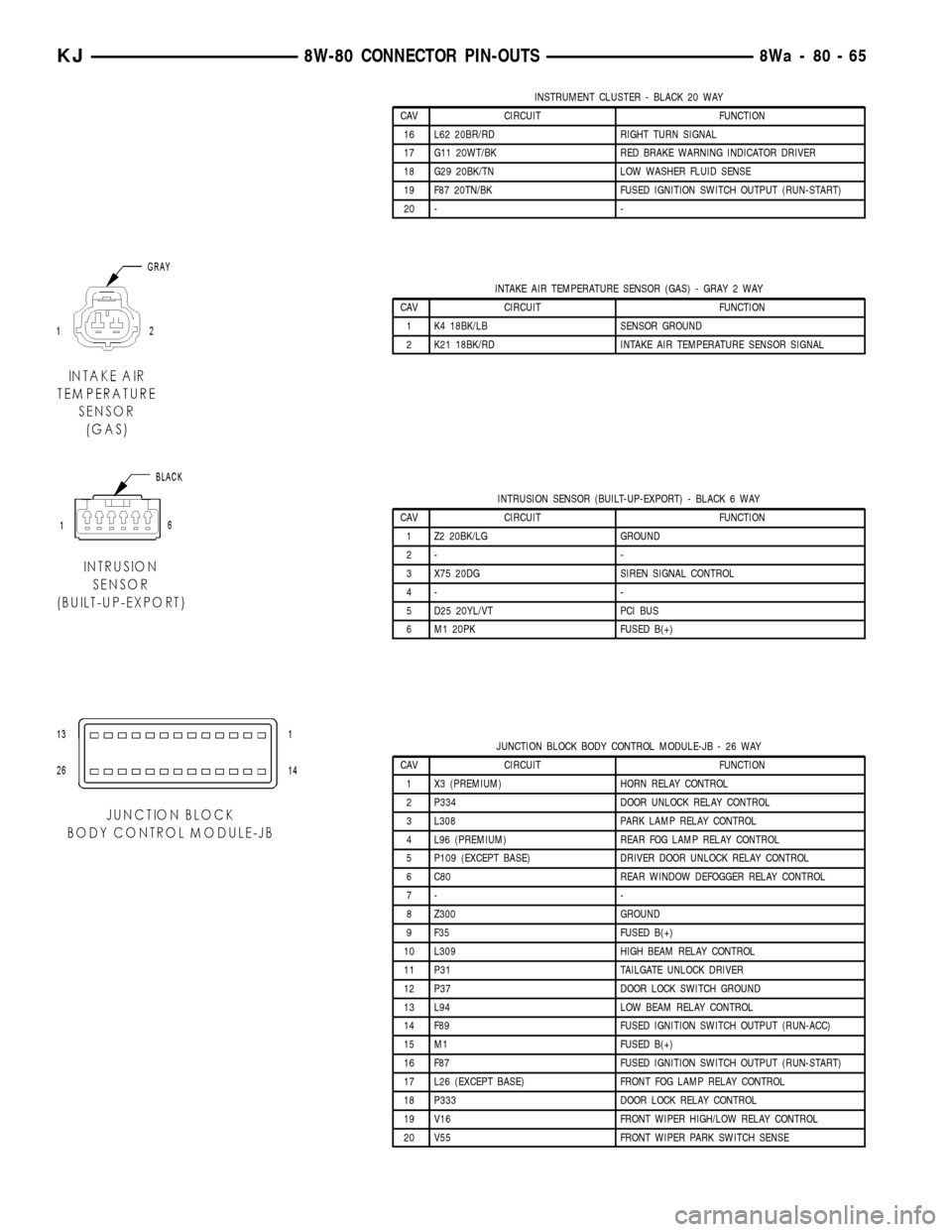
INSTRUMENT CLUSTER - BLACK 20 WAY
CAV CIRCUIT FUNCTION
16 L62 20BR/RD RIGHT TURN SIGNAL
17 G11 20WT/BK RED BRAKE WARNING INDICATOR DRIVER
18 G29 20BK/TN LOW WASHER FLUID SENSE
19 F87 20TN/BK FUSED IGNITION SWITCH OUTPUT (RUN-START)
20 - -
INTAKE AIR TEMPERATURE SENSOR (GAS) - GRAY 2 WAY
CAV CIRCUIT FUNCTION
1 K4 18BK/LB SENSOR GROUND
2 K21 18BK/RD INTAKE AIR TEMPERATURE SENSOR SIGNAL
INTRUSION SENSOR (BUILT-UP-EXPORT) - BLACK 6 WAY
CAV CIRCUIT FUNCTION
1 Z2 20BK/LG GROUND
2- -
3 X75 20DG SIREN SIGNAL CONTROL
4- -
5 D25 20YL/VT PCI BUS
6 M1 20PK FUSED B(+)
JUNCTION BLOCK BODY CONTROL MODULE-JB - 26 WAY
CAV CIRCUIT FUNCTION
1 X3 (PREMIUM) HORN RELAY CONTROL
2 P334 DOOR UNLOCK RELAY CONTROL
3 L308 PARK LAMP RELAY CONTROL
4 L96 (PREMIUM) REAR FOG LAMP RELAY CONTROL
5 P109 (EXCEPT BASE) DRIVER DOOR UNLOCK RELAY CONTROL
6 C80 REAR WINDOW DEFOGGER RELAY CONTROL
7- -
8 Z300 GROUND
9 F35 FUSED B(+)
10 L309 HIGH BEAM RELAY CONTROL
11 P31 TAILGATE UNLOCK DRIVER
12 P37 DOOR LOCK SWITCH GROUND
13 L94 LOW BEAM RELAY CONTROL
14 F89 FUSED IGNITION SWITCH OUTPUT (RUN-ACC)
15 M1 FUSED B(+)
16 F87 FUSED IGNITION SWITCH OUTPUT (RUN-START)
17 L26 (EXCEPT BASE) FRONT FOG LAMP RELAY CONTROL
18 P333 DOOR LOCK RELAY CONTROL
19 V16 FRONT WIPER HIGH/LOW RELAY CONTROL
20 V55 FRONT WIPER PARK SWITCH SENSE
KJ8W-80 CONNECTOR PIN-OUTS8Wa-80-65