2002 JEEP LIBERTY Rear lower control arm
[x] Cancel search: Rear lower control armPage 24 of 1803

STANDARD PROCEDURE
STANDARD PROCEDURE - HEIGHT
MEASUREMENT
RIDE HEIGHT
NOTE: The suspension is non-adjustable.
The vehicle suspension height should be measured
before performing wheel alignment procedure. Also
when front suspension components have been
replaced. This measure must be performed with the
vehicle supporting it's own weight and taken on both
sides of the vehicle.
Front and rear ride heights are not adjustable. The
spring selections at assembly determine ride height
for acceptable appearance of the vehicle. Ride height
dimensions assume full fluids (including fuel) and
zero passengers. Refer to the table below for front
ride height dimensions.
Vehicle ride height audits should be performed uti-
lizing the following procedure:
(1) Drive the vehicle straight and forward on a
non-tacky surface for a minimum of 20 feet to neu-
tralize track width.
(2) Bounce the front of the vehicle five times.
(3) Measure and record the dimensions
FRONT RIDE HEIGHT Front ride height is
defined by the relative vertical distance between the
spindle center line and the rear pivot point of the
front lower control arm to cradle attachment. The
spindle center line is to be measured at the outer
wheel face (point A). The rear pivot point is to be
measured at the center of the cam bolt (point B) at
its rearward most end (nut end). (Fig. 2)REAR RIDE HEIGHT Rear ride height is defined
by the relative vertical distance between the top of
the lower spring seat strike surface and the bottom
of the jounce cup (true metal to metal jounce travel).
This is to be measured vertically inside the coil from
the point intersecting the inboard edge and the for/
aft center of the jounce cup (point C) down to the
strike surface (point D). (Fig. 3)
Measurement Target Minimum Maximum
Front Ride
Height
Distance AB48.8 mm
Z=996.81
- 948.0338.8mm 58.8mm
Front Cross
Ride Height
Left - Right0.0 mm -10.0 mm 10.0 mm
Rear Ride
Height
Distance CD116.1 mm 106.1 mm 126.1 mm
Rear Cross
Ride Height
Left - Right0.0 mm -10.0 mm 10.0 mm
Fig. 2 FRONT RIDE HEIGHT MESUREMENT
1 - POINT - A
2 - POINT - B
Fig. 3 REAR RIDE HEIGHT MEASUREMENT
1 - POINT - C
2 - POINT - D
2 - 4 WHEEL ALIGNMENTKJ
WHEEL ALIGNMENT (Continued)
Page 25 of 1803
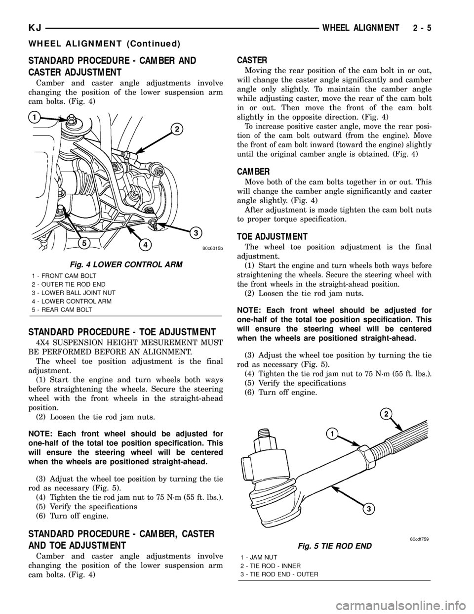
STANDARD PROCEDURE - CAMBER AND
CASTER ADJUSTMENT
Camber and caster angle adjustments involve
changing the position of the lower suspension arm
cam bolts. (Fig. 4)
STANDARD PROCEDURE - TOE ADJUSTMENT
4X4 SUSPENSION HEIGHT MESUREMENT MUST
BE PERFORMED BEFORE AN ALIGNMENT.
The wheel toe position adjustment is the final
adjustment.
(1) Start the engine and turn wheels both ways
before straightening the wheels. Secure the steering
wheel with the front wheels in the straight-ahead
position.
(2) Loosen the tie rod jam nuts.
NOTE: Each front wheel should be adjusted for
one-half of the total toe position specification. This
will ensure the steering wheel will be centered
when the wheels are positioned straight-ahead.
(3) Adjust the wheel toe position by turning the tie
rod as necessary (Fig. 5).
(4)
Tighten the tie rod jam nut to 75 N´m (55 ft. lbs.).
(5) Verify the specifications
(6) Turn off engine.
STANDARD PROCEDURE - CAMBER, CASTER
AND TOE ADJUSTMENT
Camber and caster angle adjustments involve
changing the position of the lower suspension arm
cam bolts. (Fig. 4)
CASTER
Moving the rear position of the cam bolt in or out,
will change the caster angle significantly and camber
angle only slightly. To maintain the camber angle
while adjusting caster, move the rear of the cam bolt
in or out. Then move the front of the cam bolt
slightly in the opposite direction. (Fig. 4)
To increase positive caster angle, move the rear posi-
tion of the cam bolt outward (from the engine). Move
the front of cam bolt inward (toward the engine) slightly
until the original camber angle is obtained. (Fig. 4)
CAMBER
Move both of the cam bolts together in or out. This
will change the camber angle significantly and caster
angle slightly. (Fig. 4)
After adjustment is made tighten the cam bolt nuts
to proper torque specification.
TOE ADJUSTMENT
The wheel toe position adjustment is the final
adjustment.
(1)
Start the engine and turn wheels both ways before
straightening the wheels. Secure the steering wheel with
the front wheels in the straight-ahead position.
(2) Loosen the tie rod jam nuts.
NOTE: Each front wheel should be adjusted for
one-half of the total toe position specification. This
will ensure the steering wheel will be centered
when the wheels are positioned straight-ahead.
(3) Adjust the wheel toe position by turning the tie
rod as necessary (Fig. 5).
(4)
Tighten the tie rod jam nut to 75 N´m (55 ft. lbs.).
(5) Verify the specifications
(6) Turn off engine.
Fig. 5 TIE ROD END
1 - JAM NUT
2 - TIE ROD - INNER
3 - TIE ROD END - OUTER
Fig. 4 LOWER CONTROL ARM
1 - FRONT CAM BOLT
2 - OUTER TIE ROD END
3 - LOWER BALL JOINT NUT
4 - LOWER CONTROL ARM
5 - REAR CAM BOLT
KJWHEEL ALIGNMENT 2 - 5
WHEEL ALIGNMENT (Continued)
Page 30 of 1803

(5) Install the hub/bearing. (Refer to 2 - SUSPEN-
SION/FRONT/HUB / BEARING - INSTALLATION).
(6) Install the axle shaft nut. Tighten the nut to
135 N´m (96 ft.lbs.).(if equipped with four wheel
drive).
(7) Install the wheel speed sensor. (Refer to 5 -
BRAKES/ELECTRICAL/FRONT WHEEL SPEED
SENSOR - INSTALLATION).
(8) Install the disc brake rotor. (Refer to 5 -
BRAKES/HYDRAULIC/MECHANICAL/ROTORS -
INSTALLATION).
(9) Install the caliper adapter. (Refer to 5 -
BRAKES/HYDRAULIC/MECHANICAL/DISC
BRAKE CALIPER ADAPTER - INSTALLATION).
(10) Install the tire and wheel assembly. (Refer to
22 - TIRES/WHEELS/WHEELS - STANDARD PRO-
CEDURE).
(11) Perform the set toe procedure (Refer to 2 -
SUSPENSION/WHEEL ALIGNMENT - STANDARD
PROCEDURE).
LOWER BALL JOINT
DIAGNOSIS AND TESTING - LOWER BALL
JOINT
(1) Raise the vehicle on a drive-on hoist.
NOTE: If a drive-on hoist is not available, use
wooden blocks with jack stands to support the
lower control arm in the ball joint area. Place the
jack stands appropriately and lower the hoist plac-
ing weight on the lower control arm. The lower con-
trol arms should now be supporting the vehicle
weight.
(2) With the use of jack stands, lift the front end
off the hoist and position wooden blocks underneath
both lower control arms supporting the vehicles
weight.
(3) Remove the tire and wheel assembly.
(4) Attach a dial indicator to the base of the lower
control arm and align the dial indicator's contact
point with the direction of the stud axis, touch the
machined flat on the knuckle and zero the dial indi-
cator. (Fig. 2)
NOTE: Use care when applying the load to the
knuckle, so the parts are not damaged using care
not to tear the boot.
(5) From the front of the vehicle, insert a pry bar
to get it rested on the lower control arm and use
lever principle to push the knuckle up until the arm
of the dial indicator no longer moves.(6) Record the ball joint movement on each side of
the vehicle. The end play is acceptable with no more
than 1.5mm of end play back to back.LOWER CONTROL ARM
REMOVAL
(1) Raise and support the vehicle.
(2) Remove the tire and wheel assembly.
(3) Remove the lower clevis bracket bolt at the
lower control arm.
(4) Remove the stabilizer link bolt at the lower
control arm.
(5) Remove the lower ball joint nut.
(6) Separate the lower ball joint from the lower
control arm using tool C-4150A.
NOTE: Marking the lower control arm pivot bolts
front and rear will aid in the assembly procedure.
(7) Mark the lower control arm pivot bolts front
and rear.
(8) Remove the front cam/pivot bolt. (Fig. 3)
(9) Remove the rear cam/pivot bolt. (Fig. 3)
(10) Remove the lower control arm from the vehi-
cle.
INSTALLATION
(1) Install the lower control arm to the vehicle.
(2) Install the rear cam/pivot bolt.
(3) Install the front cam/pivot bolt.
(4) Install the lower ball joint nut. Tighten the nut
to 81 N´m (60 ft.lbs.)
Fig. 2 SUSPENSION IN THE CURB POSITION
1-PRYBAR
2 - BALL JOINT
3 - DIAL INDICATOR
4 - WOODEN BLOCK OR SUPPORT
5 - CLAMP
2 - 10 FRONTKJ
KNUCKLE (Continued)
Page 31 of 1803

(5) Align the marks front and rear at the cam/
pivot bolts and tighten the bolts. Tighten the bolts to
170 N´m (125 ft.lbs.)
(6) Install the stabilizer link bolt at the lower con-
trol arm. Tighten the bolt to 136 N´m (100 ft.lbs.)
(7) Install the lower clevis bracket bolt at the
lower control arm. Tighten the bolt to 150 N´m (110
ft.lbs.)
(8) Install the tire and wheel assembly. (Refer to
22 - TIRES/WHEELS/WHEELS - STANDARD PRO-
CEDURE).
(9) Perform a full wheel alignment (Refer to 2 -
SUSPENSION/WHEEL ALIGNMENT - STANDARD
PROCEDURE).
SHOCK
REMOVAL
REMOVAL - LEFT SIDE
(1) Disconnect the battery.
(2) Remove the battery (Refer to 8 - ELECTRI-
CAL/BATTERY SYSTEM/BATTERY - REMOVAL).
(3) Unclip the power center and move it to the side
out of the way.
(4) Remove the battery tray (Refer to 8 - ELEC-
TRICAL/BATTERY SYSTEM/TRAY - REMOVAL).
(5) Disconnect the battery temperature sensor
from the battery tray.
(6) Remove the four upper shock mounting nuts.
(7) Raise and support the vehicle.(8) Remove the left tire and wheel assembly.
(9) Remove the lower bolt at the lower control
securing the clevis bracket.
(10) Remove the stabilizer link (Refer to 2 - SUS-
PENSION/FRONT/STABILIZER LINK - REMOVAL).
(11) Remove the lower ball joint nut.
(12) Seperate the lower ball joint from the lower
control arm using tool C-4150A.
(13) Rotate the lower control arm downward to
allow access.
(14) Remove the clevis bracket at the shock.
(15) Remove the shock assembly from the vehicle.
(Fig. 4)
(16) Remove the spring from the shock (if needed).
REMOVAL - RIGHT SIDE
(1) Remove the air box (Refer to 9 - ENGINE/AIR
INTAKE SYSTEM/AIR CLEANER ELEMENT -
REMOVAL).
(2) Remove the two cruise control servo mounting
nuts.
(3) Remove the upper shock mounting nuts.
(4) Raise and support the vehicle.
(5) Remove the right side tire assembly.
(6) Remove the lower bolt at the lower control
securing the clevis bracket.
(7) Remove the stabilizer link (Refer to 2 - SUS-
PENSION/FRONT/STABILIZER LINK - REMOVAL).
(8) Remove the lower ball joint nut.
(9) Seperate the lower ball joint from the lower
control arm using tool C-4150A.
(10) Rotate the lower control arm downward to
allow access.
Fig. 3 LOWER CONTROL ARM
1 - FRONT CAM BOLT
2 - OUTER TIE ROD END
3 - LOWER BALL JOINT NUT
4 - LOWER CONTROL ARM
5 - REAR CAM BOLT
Fig. 4 SHOCK ASSEMBLY
1 - SPRING
2 - JOUNCE BUMPER
3 - SHOCK
4 - UPPER CONTROL ARM
KJFRONT 2 - 11
LOWER CONTROL ARM (Continued)
Page 34 of 1803

STABILIZER BAR
REMOVAL
(1) Raise and support the vehicle.
(2) Remove the tire and wheel assembly.
(3) Remove the upper stabilizer link bolts at the
stabilizer bar.
(4) Remove the stabilizer bar bushing clamps from
the frame (Fig. 8).
(5) Remove the stabilizer bar from the vehicle.
INSTALLATION
(1) Install the stabilizer bar to the vehicle.
(2) Install the stabilizer bar bushing clamps (Fig.
8). Tighten the nuts to 149 N´m (110 ft.lbs.).
(3) Install the upper stabilizer link bolts and
washer at the stabilizer bar. Tighten the bolt to 136
N´m (100 ft.lbs.).
(4) Install the tire and wheel assembly. (Refer to
22 - TIRES/WHEELS/WHEELS - STANDARD PRO-
CEDURE).
(5) Lower the vehicle.
STABILIZER LINK
REMOVAL
(1) Raise and support the vehicle.
(2) Remove the tire and wheel assembly.
(3) Remove the lower stabilizer link bolt at the
lower control arm.
(4) Remove the upper stabilizer link bolt at the
stabilizer bar.
(5) Remove the stabilizer link. (Fig. 9)
INSTALLATION
(1) Install the stabilizer link (Fig. 9).
(2) Install the upper stabilizer link bolt and
washer at the stabilizer bar. Tighten the bolt to 136
N´m (100 ft.lbs.).
(3) Install the lower stabilizer link bolt and
washer at the lower control arm. Tighten the nut to
115 N´m (85 ft.lbs.).
(4) Install the tire and wheel assembly. (Refer to
22 - TIRES/WHEELS/WHEELS - STANDARD PRO-
CEDURE).
UPPER CONTROL ARM
REMOVAL
REMOVAL - RIGHT SIDE
(1) Raise and support the vehicle.
(2) Remove the right side tire and wheel assembly.
(3) Remove the upper ball joint nut.
(4) Separate the upper ball joint from the steering
knuckle using tool C-4150A.
(5) Lower the vehicle.
(6) Remove the air box (Refer to 9 - ENGINE/AIR
INTAKE SYSTEM/AIR CLEANER ELEMENT -
REMOVAL).
(7) Remove the cruise control servo mounting nuts.
(8) Remove the upper control arm rear bolt.
(9) Remove the upper control arm front bolt.
(10) Remove the upper control arm from the vehi-
cle.
Fig. 8 SWAY BAR
1-SWAYBAR
2 - SWAY BAR BUSHINGS
Fig. 9 STABILIZER BAR LINK
1 - STABILIZER BAR
2 - STABILIZER BAR LINK
2 - 14 FRONTKJ
Page 35 of 1803

REMOVAL - LEFT SIDE
(1) Raise and support the vehicle.
(2) Remove the left side tire and wheel assembly.
(3) Remove the upper ball joint nut.
(4) Separate the upper ball joint from the steering
knuckle using tool C-4150A.
(5) Lower the vehicle.
(6) Remove the battery (Refer to 8 - ELECTRI-
CAL/BATTERY SYSTEM/BATTERY - REMOVAL).
(7) Unclip the power center and move it to the side
out of the way.
(8) Remove the battery tray (Refer to 8 - ELEC-
TRICAL/BATTERY SYSTEM/TRAY - REMOVAL).
(9) Disconnect the battery temperature sensor
from the battery tray.
(10) Remove the upper control arm rear bolt by
using a ratchet and extension under the steering
shaft and positioned by the power steering reservoir.
(Fig. 10)
(11) Remove the upper control arm front bolt.
(12) Remove the upper control arm from the vehi-
cle.
INSTALLATION
INSTALLATION - RIGHT SIDE
(1) Install the upper control arm to the vehicle.
(2) Install the upper control arm front bolt.
Tighten the bolt to 122 N´m (90 ft.lbs.).
(3) Install the upper control arm rear bolt. Tighten
the bolt to 122 N´m (90 ft.lbs.).
(4) Install the cruise control servo mounting nuts.(5) Install the air box (Refer to 9 - ENGINE/AIR
INTAKE SYSTEM/AIR CLEANER ELEMENT -
INSTALLATION).
(6) Install the upper ball joint nut. Tighten the nut
to 81 N´m (60 ft.lbs.).
(7) Install the right side tire and wheel assembly.
(Refer to 22 - TIRES/WHEELS/WHEELS - STAN-
DARD PROCEDURE).
(8) Lower the vehicle.
(9) Set the toe and center the steering wheel
(Refer to 2 - SUSPENSION/WHEEL ALIGNMENT -
STANDARD PROCEDURE).
INSTALLATION - LEFT SIDE
(1) Install the upper control arm to the vehicle.
(2) Install the upper control arm front bolt (Fig.
11). Tighten the bolt to 122 N´m (90 ft.lbs.).
(3) Install the upper control arm rear bolt (Fig.
11). Tighten the bolt to 122 N´m (90 ft.lbs.).
(4) Reconnect the battery temperature sensor to
the battery tray.
(5) Install the battery tray (Refer to 8 - ELECTRI-
CAL/BATTERY SYSTEM/TRAY - INSTALLATION).
(6) Install the battery (Refer to 8 - ELECTRICAL/
BATTERY SYSTEM/BATTERY - INSTALLATION).
(7) Reclip and mount the power center.
(8) Install the upper ball joint nut (Fig. 11).
Tighten the nut to 81 N´m (60 ft.lbs.).
(9) Install the left side tire and wheel assembly.
(Refer to 22 - TIRES/WHEELS/WHEELS - STAN-
DARD PROCEDURE).
(10) Lower the vehicle.
(11) Set the toe and center the steering wheel
(Refer to 2 - SUSPENSION/WHEEL ALIGNMENT -
STANDARD PROCEDURE).
Fig. 10 REAR BOLT
1 - STEERING SHAFT
2 - REAR BOLT
3 - RATCHET WITH AN EXTENSION
Fig. 11 UPPER CONTROL ARM
KJFRONT 2 - 15
UPPER CONTROL ARM (Continued)
Page 36 of 1803

REAR
TABLE OF CONTENTS
page page
REAR
DESCRIPTION.........................16
WARNING.............................16
DIAGNOSIS AND TESTING - REAR
SUSPENSION........................17
SPECIFICATIONS
TORQUE CHART......................17
SHOCK
REMOVAL.............................18
INSTALLATION.........................18
SPRING
REMOVAL.............................18
INSTALLATION.........................18
JOUNCE BUMPER
REMOVAL.............................19
INSTALLATION.........................19
STABILIZER BAR
REMOVAL.............................19INSTALLATION.........................19
UPPER BALL JOINT
REMOVAL.............................20
INSTALLATION.........................20
UPPER CONTROL ARM
DESCRIPTION - UPPER SUSPENSION ARM,
BUSHINGS, AND BALL JOINT............20
OPERATION - UPPER SUSPENSION ARM,
BUSHINGS, AND BALL JOINT............20
REMOVAL.............................20
INSTALLATION.........................21
LOWER CONTROL ARM
DESCRIPTION.........................21
OPERATION...........................21
REMOVAL.............................21
INSTALLATION.........................21
REAR
DESCRIPTION
The rear suspension (Fig. 1) is comprised of :
²Drive axle
²Shock absorbers
²Coil springs
²Lower suspension arms
²Upper suspension arm
²Stabilizer bar
CAUTION: Suspension components with rubber/ure-
thane bushings should be tightened with the vehi-
cle at normal ride height. It is important to have the
springs supporting the weight of the vehicle when
the fasteners are torqued. This will maintain vehicle
ride comfort and prevent premature bushing wear.
WARNING
WARNING:: Suspension components with rubber
bushings must be tightened with the vehicle at nor-
mal ride height. It is important to have the springs
supporting the weight of the vehicle when the fas-
teners are torqued. If springs are not at their normal
ride position, vehicle ride comfort will be affected
and cause premature bushing wear.
Fig. 1 REAR SUSPENSION
1 - COIL SPRING
2 - UPPER SUSPENSION ARM
3 - STABILIZER BAR
4 - LOWER SUSPENSION ARM
5 - SHOCK
2 - 16 REARKJ
Page 40 of 1803

UPPER BALL JOINT
REMOVAL
(1) Raise and support the vehicle.
(2) Support the rear axle with a hydraulic jack.
(3) Remove the ball joint pinch bolt from the top of
the axle. (Fig. 7)
(4) Seperate the ball joint arm assembly from the
differential housing by prying upwards.
INSTALLATION
(1)Raise the rear axle with a hydraulic jack to align
the ball joint with the differential housing bracket.
(2) Insert the ball joint into the differential hous-
ing bracket.
(3) Install the ball joint pinch bolt and tighten to
95 N´m (70 ft. lbs.). (Fig. 7).
(4) Remove the supports and lower the vehicle.
UPPER CONTROL ARM
DESCRIPTION - UPPER SUSPENSION ARM,
BUSHINGS, AND BALL JOINT
The suspension arm uses vertical spool bushings to
isolate road noise. The suspension arm is bolted
through bushings to cage nuts in the body and a ball
joint to the top of the differential housing.
OPERATION - UPPER SUSPENSION ARM,
BUSHINGS, AND BALL JOINT
The upper suspension arm provides fore/aft and
lateral location of the rear axle. The suspension arm
travel is limited through the use of jounce bumpers
in compression and shock absorbers in rebound.
REMOVAL
(1) Raise and support the vehicle.
(2) Support the rear axle with a hydraulic jack.
(3) Remove the ball joint pinch bolt from the top of
the differential housing bracket (Fig. 7).
(4) Remove partial nuts from the heat shield in
order to lower the shield down enough to get the
proper clearence to remove the right side bolt from
the body.
(5) Remove the upper suspension arm mounting
bolts from the body and remove the arm (Fig. 8).
(6) Remove the support bracket mounting bolts if
needed. (Fig. 9)
Fig. 7 BALL JOINT PINCH BOLT
1 - UPPER BALL JOINT
2 - PINCH BOLTFig. 8 UPPER CONTROL ARM
1 - BODY MOUNTS
2 - UPPER BALL JOINT
3 - STABILIZER BAR
4 - UPPER CONTROL ARM
5 - LOWER CONTROL ARM
Fig. 9 BALL JOINT BRACKET
1 - UPPER BALL JOINT
2 - SUPPORT BRACKET BOLTS
2 - 20 REARKJ