2002 JEEP LIBERTY Power outlet
[x] Cancel search: Power outletPage 936 of 1803

8W-41 HORN/CIGAR LIGHTER/POWER OUTLET
Component Page
Body Control Module................ 8Wa-41-2
Cigar Lighter...................... 8Wa-41-3
Clockspring........................ 8Wa-41-2
Fuse 1............................ 8Wa-41-3
Fuse 3............................ 8Wa-41-2
Fuse 16........................... 8Wa-41-3
Fuse 31........................... 8Wa-41-3
G111 ............................. 8Wa-41-2
G202............................. 8Wa-41-3Component Page
G310............................. 8Wa-41-3
High Note Horn.................... 8Wa-41-2
Horn Relay........................ 8Wa-41-2
Horn Switch....................... 8Wa-41-2
Junction Block.................... 8Wa-41-2, 3
Low Note Horn..................... 8Wa-41-2
Power Outlet....................... 8Wa-41-3
Rear Power Outlet.................. 8Wa-41-3
KJ8W-41 HORN/CIGAR LIGHTER/POWER OUTLET8Wa-41-1
Page 1058 of 1803
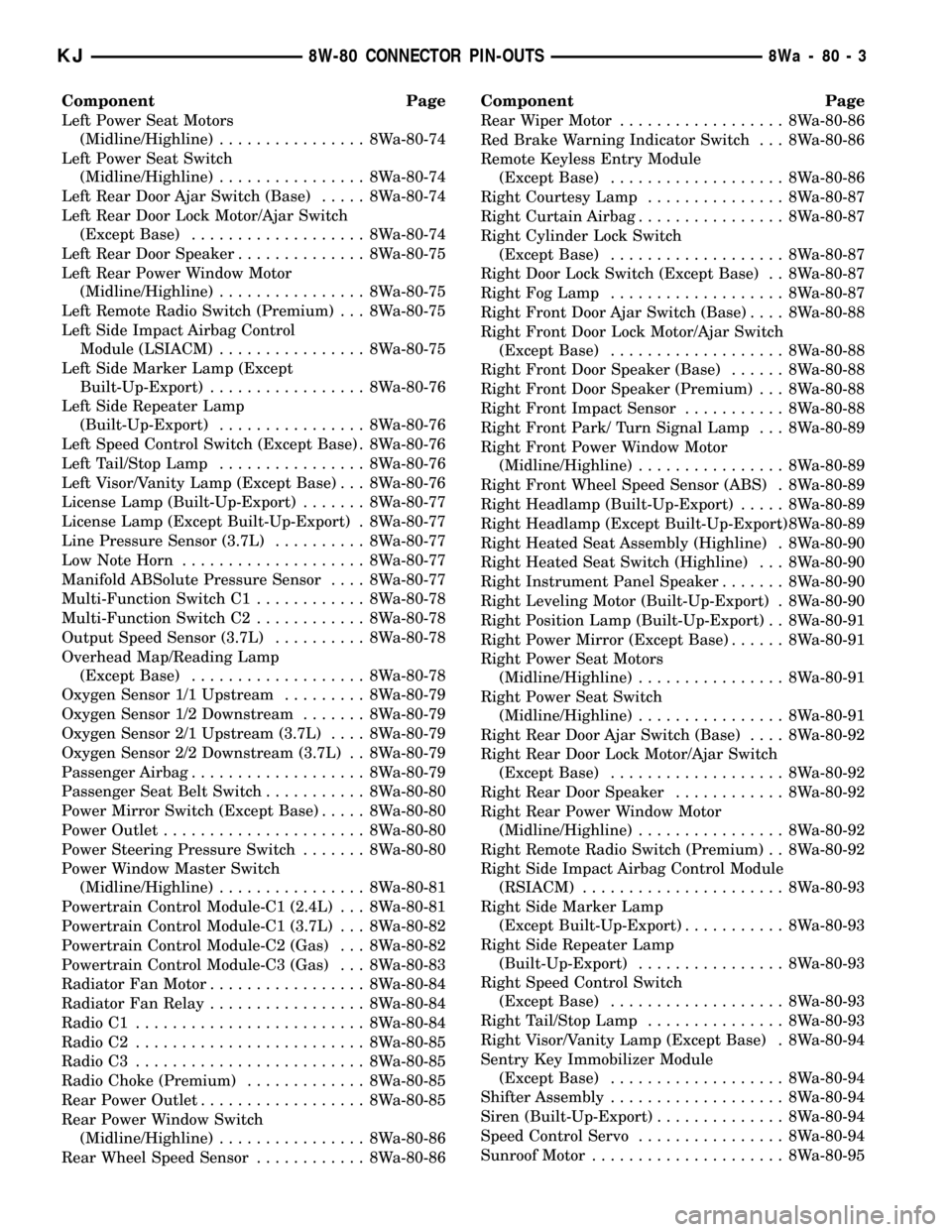
Component Page
Left Power Seat Motors
(Midline/Highline)................ 8Wa-80-74
Left Power Seat Switch
(Midline/Highline)................ 8Wa-80-74
Left Rear Door Ajar Switch (Base)..... 8Wa-80-74
Left Rear Door Lock Motor/Ajar Switch
(Except Base)................... 8Wa-80-74
Left Rear Door Speaker.............. 8Wa-80-75
Left Rear Power Window Motor
(Midline/Highline)................ 8Wa-80-75
Left Remote Radio Switch (Premium) . . . 8Wa-80-75
Left Side Impact Airbag Control
Module (LSIACM)................ 8Wa-80-75
Left Side Marker Lamp (Except
Built-Up-Export)................. 8Wa-80-76
Left Side Repeater Lamp
(Built-Up-Export)................ 8Wa-80-76
Left Speed Control Switch (Except Base) . 8Wa-80-76
Left Tail/Stop Lamp................ 8Wa-80-76
Left Visor/Vanity Lamp (Except Base) . . . 8Wa-80-76
License Lamp (Built-Up-Export)....... 8Wa-80-77
License Lamp (Except Built-Up-Export) . 8Wa-80-77
Line Pressure Sensor (3.7L).......... 8Wa-80-77
Low Note Horn.................... 8Wa-80-77
Manifold ABSolute Pressure Sensor.... 8Wa-80-77
Multi-Function Switch C1............ 8Wa-80-78
Multi-Function Switch C2............ 8Wa-80-78
Output Speed Sensor (3.7L).......... 8Wa-80-78
Overhead Map/Reading Lamp
(Except Base)................... 8Wa-80-78
Oxygen Sensor 1/1 Upstream......... 8Wa-80-79
Oxygen Sensor 1/2 Downstream....... 8Wa-80-79
Oxygen Sensor 2/1 Upstream (3.7L).... 8Wa-80-79
Oxygen Sensor 2/2 Downstream (3.7L) . . 8Wa-80-79
Passenger Airbag................... 8Wa-80-79
Passenger Seat Belt Switch........... 8Wa-80-80
Power Mirror Switch (Except Base)..... 8Wa-80-80
Power Outlet...................... 8Wa-80-80
Power Steering Pressure Switch....... 8Wa-80-80
Power Window Master Switch
(Midline/Highline)................ 8Wa-80-81
Powertrain Control Module-C1 (2.4L) . . . 8Wa-80-81
Powertrain Control Module-C1 (3.7L) . . . 8Wa-80-82
Powertrain Control Module-C2 (Gas) . . . 8Wa-80-82
Powertrain Control Module-C3 (Gas) . . . 8Wa-80-83
Radiator Fan Motor................. 8Wa-80-84
Radiator Fan Relay................. 8Wa-80-84
Radio C1......................... 8Wa-80-84
Radio C2......................... 8Wa-80-85
Radio C3......................... 8Wa-80-85
Radio Choke (Premium)............. 8Wa-80-85
Rear Power Outlet.................. 8Wa-80-85
Rear Power Window Switch
(Midline/Highline)................ 8Wa-80-86
Rear Wheel Speed Sensor............ 8Wa-80-86Component Page
Rear Wiper Motor.................. 8Wa-80-86
Red Brake Warning Indicator Switch . . . 8Wa-80-86
Remote Keyless Entry Module
(Except Base)................... 8Wa-80-86
Right Courtesy Lamp............... 8Wa-80-87
Right Curtain Airbag................ 8Wa-80-87
Right Cylinder Lock Switch
(Except Base)................... 8Wa-80-87
Right Door Lock Switch (Except Base) . . 8Wa-80-87
Right Fog Lamp................... 8Wa-80-87
Right Front Door Ajar Switch (Base).... 8Wa-80-88
Right Front Door Lock Motor/Ajar Switch
(Except Base)................... 8Wa-80-88
Right Front Door Speaker (Base)...... 8Wa-80-88
Right Front Door Speaker (Premium) . . . 8Wa-80-88
Right Front Impact Sensor........... 8Wa-80-88
Right Front Park/ Turn Signal Lamp . . . 8Wa-80-89
Right Front Power Window Motor
(Midline/Highline)................ 8Wa-80-89
Right Front Wheel Speed Sensor (ABS) . 8Wa-80-89
Right Headlamp (Built-Up-Export)..... 8Wa-80-89
Right Headlamp (Except Built-Up-Export). 8Wa-80-89
Right Heated Seat Assembly (Highline) . 8Wa-80-90
Right Heated Seat Switch (Highline) . . . 8Wa-80-90
Right Instrument Panel Speaker....... 8Wa-80-90
Right Leveling Motor (Built-Up-Export) . 8Wa-80-90
Right Position Lamp (Built-Up-Export) . . 8Wa-80-91
Right Power Mirror (Except Base)...... 8Wa-80-91
Right Power Seat Motors
(Midline/Highline)................ 8Wa-80-91
Right Power Seat Switch
(Midline/Highline)................ 8Wa-80-91
Right Rear Door Ajar Switch (Base).... 8Wa-80-92
Right Rear Door Lock Motor/Ajar Switch
(Except Base)................... 8Wa-80-92
Right Rear Door Speaker............ 8Wa-80-92
Right Rear Power Window Motor
(Midline/Highline)................ 8Wa-80-92
Right Remote Radio Switch (Premium) . . 8Wa-80-92
Right Side Impact Airbag Control Module
(RSIACM)...................... 8Wa-80-93
Right Side Marker Lamp
(Except Built-Up-Export)........... 8Wa-80-93
Right Side Repeater Lamp
(Built-Up-Export)................ 8Wa-80-93
Right Speed Control Switch
(Except Base)................... 8Wa-80-93
Right Tail/Stop Lamp............... 8Wa-80-93
Right Visor/Vanity Lamp (Except Base) . 8Wa-80-94
Sentry Key Immobilizer Module
(Except Base)................... 8Wa-80-94
Shifter Assembly................... 8Wa-80-94
Siren (Built-Up-Export).............. 8Wa-80-94
Speed Control Servo................ 8Wa-80-94
Sunroof Motor..................... 8Wa-80-95
KJ8W-80 CONNECTOR PIN-OUTS8Wa-80-3
Page 1135 of 1803
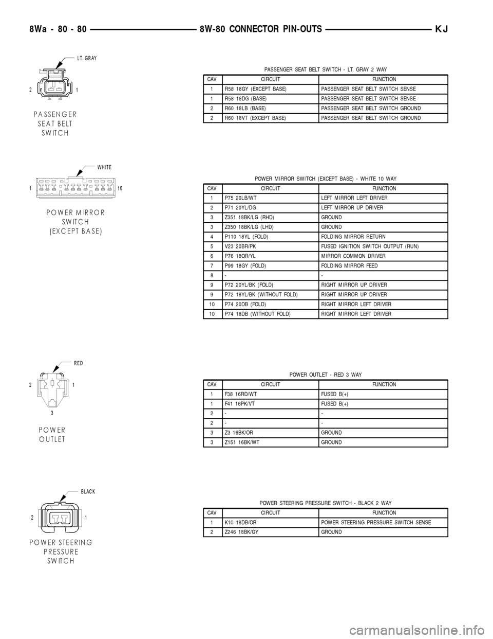
PASSENGER SEAT BELT SWITCH - LT. GRAY 2 WAY
CAV CIRCUIT FUNCTION
1 R58 18GY (EXCEPT BASE) PASSENGER SEAT BELT SWITCH SENSE
1 R58 18DG (BASE) PASSENGER SEAT BELT SWITCH SENSE
2 R60 18LB (BASE) PASSENGER SEAT BELT SWITCH GROUND
2 R60 18VT (EXCEPT BASE) PASSENGER SEAT BELT SWITCH GROUND
POWER MIRROR SWITCH (EXCEPT BASE) - WHITE 10 WAY
CAV CIRCUIT FUNCTION
1 P75 20LB/WT LEFT MIRROR LEFT DRIVER
2 P71 20YL/DG LEFT MIRROR UP DRIVER
3 Z351 18BK/LG (RHD) GROUND
3 Z350 18BK/LG (LHD) GROUND
4 P110 18YL (FOLD) FOLDING MIRROR RETURN
5 V23 20BR/PK FUSED IGNITION SWITCH OUTPUT (RUN)
6 P76 18OR/YL MIRROR COMMON DRIVER
7 P99 18GY (FOLD) FOLDING MIRROR FEED
8- -
9 P72 20YL/BK (FOLD) RIGHT MIRROR UP DRIVER
9 P72 18YL/BK (WITHOUT FOLD) RIGHT MIRROR UP DRIVER
10 P74 20DB (FOLD) RIGHT MIRROR LEFT DRIVER
10 P74 18DB (WITHOUT FOLD) RIGHT MIRROR LEFT DRIVER
POWER OUTLET - RED 3 WAY
CAV CIRCUIT FUNCTION
1 F38 16RD/WT FUSED B(+)
1 F41 16PK/VT FUSED B(+)
2- -
2- -
3 Z3 16BK/OR GROUND
3 Z151 16BK/WT GROUND
POWER STEERING PRESSURE SWITCH - BLACK 2 WAY
CAV CIRCUIT FUNCTION
1 K10 18DB/OR POWER STEERING PRESSURE SWITCH SENSE
2 Z246 18BK/GY GROUND
8Wa - 80 - 80 8W-80 CONNECTOR PIN-OUTSKJ
Page 1140 of 1803
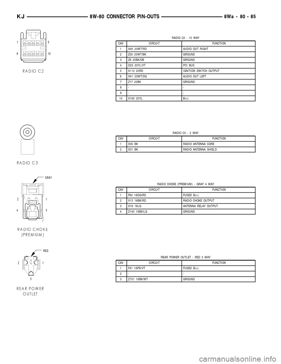
RADIO C2 - 10 WAY
CAV CIRCUIT FUNCTION
1 X40 20WT/RD AUDIO OUT RIGHT
2 Z30 20WT/BK GROUND
3 Z9 20BK/DB GROUND
4 D25 20YL/VT PCI BUS
5 X112 20RD IGNITION SWITCH OUTPUT
6 X41 20WT/DG AUDIO OUT LEFT
7 Z17 20BK GROUND
8- -
9- -
10 X160 20YL B(+)
RADIO C3-2WAY
CAV CIRCUIT FUNCTION
1 X30 BK RADIO ANTENNA CORE
2 X31 BK RADIO ANTENNA SHIELD
RADIO CHOKE (PREMIUM) - GRAY 4 WAY
CAV CIRCUIT FUNCTION
1 F60 16DG/RD FUSED B(+)
2 X13 16BK/RD RADIO CHOKE OUTPUT
3 X16 18LG ANTENNA RELAY OUTPUT
4 Z140 16BK/LG GROUND
REAR POWER OUTLET - RED 3 WAY
CAV CIRCUIT FUNCTION
1 F41 16PK/VT FUSED B(+)
2- -
3 Z151 16BK/WT GROUND
KJ8W-80 CONNECTOR PIN-OUTS8Wa-80-85
Page 1162 of 1803
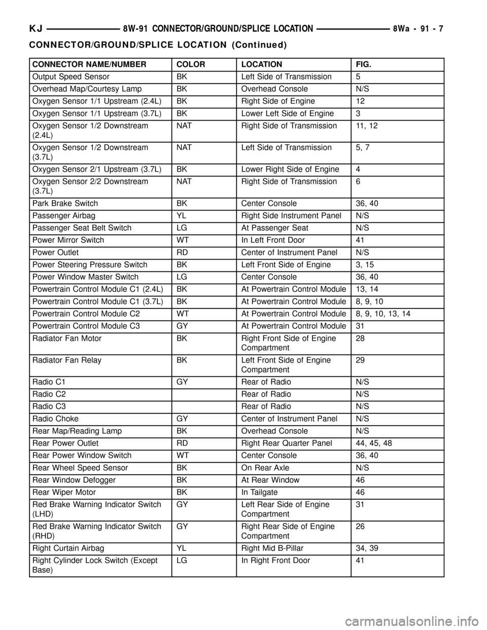
CONNECTOR NAME/NUMBER COLOR LOCATION FIG.
Output Speed Sensor BK Left Side of Transmission 5
Overhead Map/Courtesy Lamp BK Overhead Console N/S
Oxygen Sensor 1/1 Upstream (2.4L) BK Right Side of Engine 12
Oxygen Sensor 1/1 Upstream (3.7L) BK Lower Left Side of Engine 3
Oxygen Sensor 1/2 Downstream
(2.4L)NAT Right Side of Transmission 11, 12
Oxygen Sensor 1/2 Downstream
(3.7L)NAT Left Side of Transmission 5, 7
Oxygen Sensor 2/1 Upstream (3.7L) BK Lower Right Side of Engine 4
Oxygen Sensor 2/2 Downstream
(3.7L)NAT Right Side of Transmission 6
Park Brake Switch BK Center Console 36, 40
Passenger Airbag YL Right Side Instrument Panel N/S
Passenger Seat Belt Switch LG At Passenger Seat N/S
Power Mirror Switch WT In Left Front Door 41
Power Outlet RD Center of Instrument Panel N/S
Power Steering Pressure Switch BK Left Front Side of Engine 3, 15
Power Window Master Switch LG Center Console 36, 40
Powertrain Control Module C1 (2.4L) BK At Powertrain Control Module 13, 14
Powertrain Control Module C1 (3.7L) BK At Powertrain Control Module 8, 9, 10
Powertrain Control Module C2 WT At Powertrain Control Module 8, 9, 10, 13, 14
Powertrain Control Module C3 GY At Powertrain Control Module 31
Radiator Fan Motor BK Right Front Side of Engine
Compartment28
Radiator Fan Relay BK Left Front Side of Engine
Compartment29
Radio C1 GY Rear of Radio N/S
Radio C2 Rear of Radio N/S
Radio C3 Rear of Radio N/S
Radio Choke GY Center of Instrument Panel N/S
Rear Map/Reading Lamp BK Overhead Console N/S
Rear Power Outlet RD Right Rear Quarter Panel 44, 45, 48
Rear Power Window Switch WT Center Console 36, 40
Rear Wheel Speed Sensor BK On Rear Axle N/S
Rear Window Defogger BK At Rear Window 46
Rear Wiper Motor BK In Tailgate 46
Red Brake Warning Indicator Switch
(LHD)GY Left Rear Side of Engine
Compartment31
Red Brake Warning Indicator Switch
(RHD)GY Right Rear Side of Engine
Compartment26
Right Curtain Airbag YL Right Mid B-Pillar 34, 39
Right Cylinder Lock Switch (Except
Base)LG In Right Front Door 41
KJ8W-91 CONNECTOR/GROUND/SPLICE LOCATION8Wa-91-7
CONNECTOR/GROUND/SPLICE LOCATION (Continued)
Page 1167 of 1803
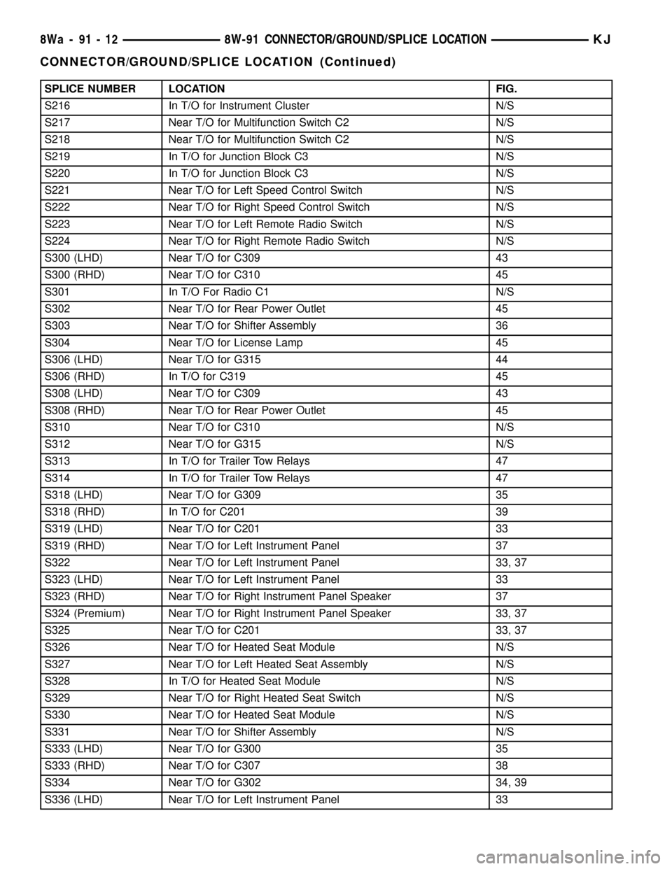
SPLICE NUMBER LOCATION FIG.
S216 In T/O for Instrument Cluster N/S
S217 Near T/O for Multifunction Switch C2 N/S
S218 Near T/O for Multifunction Switch C2 N/S
S219 In T/O for Junction Block C3 N/S
S220 In T/O for Junction Block C3 N/S
S221 Near T/O for Left Speed Control Switch N/S
S222 Near T/O for Right Speed Control Switch N/S
S223 Near T/O for Left Remote Radio Switch N/S
S224 Near T/O for Right Remote Radio Switch N/S
S300 (LHD) Near T/O for C309 43
S300 (RHD) Near T/O for C310 45
S301 In T/O For Radio C1 N/S
S302 Near T/O for Rear Power Outlet 45
S303 Near T/O for Shifter Assembly 36
S304 Near T/O for License Lamp 45
S306 (LHD) Near T/O for G315 44
S306 (RHD) In T/O for C319 45
S308 (LHD) Near T/O for C309 43
S308 (RHD) Near T/O for Rear Power Outlet 45
S310 Near T/O for C310 N/S
S312 Near T/O for G315 N/S
S313 In T/O for Trailer Tow Relays 47
S314 In T/O for Trailer Tow Relays 47
S318 (LHD) Near T/O for G309 35
S318 (RHD) In T/O for C201 39
S319 (LHD) Near T/O for C201 33
S319 (RHD) Near T/O for Left Instrument Panel 37
S322 Near T/O for Left Instrument Panel 33, 37
S323 (LHD) Near T/O for Left Instrument Panel 33
S323 (RHD) Near T/O for Right Instrument Panel Speaker 37
S324 (Premium) Near T/O for Right Instrument Panel Speaker 33, 37
S325 Near T/O for C201 33, 37
S326 Near T/O for Heated Seat Module N/S
S327 Near T/O for Left Heated Seat Assembly N/S
S328 In T/O for Heated Seat Module N/S
S329 Near T/O for Right Heated Seat Switch N/S
S330 Near T/O for Heated Seat Module N/S
S331 Near T/O for Shifter Assembly N/S
S333 (LHD) Near T/O for G300 35
S333 (RHD) Near T/O for C307 38
S334 Near T/O for G302 34, 39
S336 (LHD) Near T/O for Left Instrument Panel 33
8Wa - 91 - 12 8W-91 CONNECTOR/GROUND/SPLICE LOCATIONKJ
CONNECTOR/GROUND/SPLICE LOCATION (Continued)
Page 1317 of 1803
Possible indications of the cylinder head gasket
leaking between a cylinder and an adjacent water
jacket are:
²Engine overheating
²Loss of coolant
²Excessive steam (white smoke) emitting from
exhaust
²Coolant foaming
CYLINDER-TO-CYLINDER LEAKAGE TEST
To determine if an engine cylinder head gasket is
leaking between adjacent cylinders, follow the proce-
dures in Cylinder Compression Pressure Test (Refer
to 9 - ENGINE - DIAGNOSIS AND TESTING). An
engine cylinder head gasket leaking between adja-
cent cylinders will result in approximately a 50±70%
reduction in compression pressure.
CYLINDER-TO-WATER JACKET LEAKAGE TEST
WARNING: USE EXTREME CAUTION WHEN THE
ENGINE IS OPERATING WITH COOLANT PRES-
SURE CAP REMOVED.
VISUAL TEST METHOD
With the engine cool, remove the coolant pressure
cap. Start the engine and allow it to warm up until
thermostat opens.
If a large combustion/compression pressure leak
exists, bubbles will be visible in the coolant.
COOLING SYSTEM TESTER METHOD
WARNING: WITH COOLING SYSTEM TESTER IN
PLACE, PRESSURE WILL BUILD UP FAST. EXCES-
SIVE PRESSURE BUILT UP, BY CONTINUOUS
ENGINE OPERATION, MUST BE RELEASED TO A
SAFE PRESSURE POINT. NEVER PERMIT PRES-
SURE TO EXCEED 138 kPa (20 psi).
Install Cooling System Tester 7700 or equivalent to
pressure cap neck. Start the engine and observe the
tester's pressure gauge. If gauge pulsates with every
power stroke of a cylinder a combustion pressure
leak is evident.
CHEMICAL TEST METHOD
Combustion leaks into the cooling system can also
be checked by using Bloc-Chek Kit C-3685-A or
equivalent. Perform test following the procedures
supplied with the tool kit.
REMOVAL - CYLINDER HEAD
(1) Perform fuel system pressure release procedure
before attempting any repairs.(Refer to 14 -FUEL SYSTEM/FUEL DELIVERY - SPECIFICA-
TIONS)
(2) Disconnect battery negative cable.
(3) Drain cooling system. (Refer to 7 - COOLING -
STANDARD PROCEDURE)
(4) Remove air filter housing and inlet tube.
(5) Remove intake manifold.
(6) Remove heater tube support bracket from cyl-
inder head.
(7) Disconnect radiator upper and heater supply
hoses from water outlet connections.
(8) Remove accessory drive belts. (Refer to 7 -
COOLING/ACCESSORY DRIVE/DRIVE BELTS -
REMOVAL)
(9) Raise vehicle and remove exhaust pipe from
manifold.
(10) Remove power steering pump and set aside.
Do not disconnect lines.
(11) Remove accessory drive bracket
(12) Remove ignition coil and wires from engine.
(13) Disconnect cam sensor and fuel injector wir-
ing connectors.
(14) Remove timing belt and camshaft sprockets.
(Refer to 9 - ENGINE/VALVE TIMING/TIMING
BELT/CHAIN AND SPROCKETS - REMOVAL)
(15) Remove timing belt idler pulley and rear tim-
ing belt cover. (Refer to 9 - ENGINE/VALVE TIM-
ING/TIMING BELT / CHAIN COVER(S) -
REMOVAL)
(16) Remove cylinder head cover. (Refer to 9 -
ENGINE/CYLINDER HEAD/CYLINDER HEAD
COVER(S) - REMOVAL)
(17) Remove camshafts (Refer to 9 - ENGINE/
CYLINDER HEAD/CAMSHAFT(S) - REMOVAL).
NOTE: Identify rocker arm position to ensure cor-
rect re-installation in original position, if reused.
(18) Remove rocker arms. (Refer to 9 - ENGINE/
CYLINDER HEAD/ROCKER ARMS - REMOVAL).
(19) Remove cylinder head bolts in REVERSE
sequence of tightening.
(20) Remove cylinder head from engine block.
(21) Inspect and clean cylinder head. (Refer to 9 -
ENGINE/CYLINDER HEAD - INSPECTION) (Refer
to 9 - ENGINE/CYLINDER HEAD - CLEANING)
CLEANING
To ensure engine gasket sealing, proper surface
preparation must be performed, especially with the
use of aluminum engine components and multi-layer
steel cylinder head gaskets.
NOTE: Multi-Layer Steel (MLS) head gaskets require
a scratch free sealing surface.
9s - 20 ENGINEKJ
CYLINDER HEAD (Continued)
Page 1397 of 1803
FUEL PUMP
DESCRIPTION
The electric fuel pump is located inside of the fuel
pump module. A 12 volt, permanent magnet, electric
motor powers the fuel pump. The electric fuel pump
is not a separate, serviceable component.
OPERATION
Voltage to operate the electric pump is supplied
through the fuel pump relay.
Fuel is drawn in through a filter at the bottom of
the module and pushed through the electric motor
gearset to the pump outlet.
Check Valve Operation:The bottom section of
the fuel pump module contains a one-way check
valve to prevent fuel flow back into the tank and to
maintain fuel supply line pressure (engine warm)
when pump is not operational. It is also used to keep
the fuel supply line full of gasoline when pump is not
operational. After the vehicle has cooled down, fuel
pressure may drop to 0 psi (cold fluid contracts), but
liquid gasoline will remain in fuel supply line
between the check valve and fuel injectors.Fuel
pressure that has dropped to 0 psi on a cooled
down vehicle (engine off) is a normal condition.
Refer to the Fuel Pressure Leak Down Test for more
information.
The electric fuel pump is not a separate, service-
able component.
DIAGNOSIS AND TESTING
DIAGNOSIS AND TESTING - FUEL PUMP
CAPACITY TEST
Before performing this test, verify fuel pump
pressure. Refer to Fuel Pump Pressure Test.
Use this test in conjunction with the Fuel Pres-
sure Leak Down Test.
(1) Release fuel system pressure. Refer to Fuel
Pressure Release Procedure.
(2) Disconnect fuel supply line at fuel rail. Refer to
Quick-Connect Fittings. Some engines may require
air cleaner housing removal before line disconnection.
(3) Obtain correct Fuel Line Pressure Test Adapter
Tool Hose. Tool number 6539 is used for 5/16º fuel
lines and tool number 6631 is used for 3/8º fuel lines.
(4) Connect correct Fuel Line Pressure Test
Adapter Tool Hose into disconnected fuel supply line.
Insert other end of Adaptor Tool Hose into a gradu-
ated container.
(5) Remove fuel fill cap.(6) To activate fuel pump and pressurize system,
obtain DRBtscan tool and actuate ASD Fuel System
Test.
(7) A good fuel pump will deliver at least 1/10 liter
of fuel in 7 seconds. Do not operate fuel pump for
longer than 7 seconds with fuel line disconnected as
fuel pump module reservoir may run empty.
(a) If capacity is lower than specification, but
fuel pump can be heard operating through fuel fill
cap opening, check for a kinked/damaged fuel sup-
ply line somewhere between fuel rail and fuel
pump module.
(b) If line is not kinked/damaged, and fuel pres-
sure is OK, but capacity is low, replace fuel filter.
Refer to Fuel Filter Removal/Installation for addi-
tional information.
(c) If both fuel pressure and capacity are low,
replace bottom section of fuel pump module. Refer
to Fuel Pump Module Removal/Installation.
DIAGNOSIS AND TESTING - FUEL PUMP
PRESSURE TEST
Use this test in conjunction with the Fuel Pump
Capacity Test, Fuel Pressure Leak Down Test and
Fuel Pump Amperage Test found elsewhere in this
group.
Check Valve Operation:The bottom section of
the fuel pump module contains a one-way check
valve to prevent fuel flow back into the tank and to
maintain fuel supply line pressure (engine warm)
when pump is not operational. It is also used to keep
the fuel supply line full of gasoline when pump is not
operational. After the vehicle has cooled down, fuel
pressure may drop to 0 psi (cold fluid contracts), but
liquid gasoline will remain in fuel supply line
between the check valve and fuel injectors.Fuel
pressure that has dropped to 0 psi on a cooled
down vehicle (engine off) is a normal condition.
When the electric fuel pump is activated, fuel pres-
sure shouldimmediately(1±2 seconds) rise to spec-
ification.
The fuel system is equipped with a separate fuel
pump module mounted, fuel pressure regulator. The
fuel filter is remotely mounted. The fuel pressure
regulator is not controlled by engine vacuum.
WARNING: THE FUEL SYSTEM IS UNDER CON-
STANT FUEL PRESSURE EVEN WITH THE ENGINE
OFF. BEFORE DISCONNECTING FUEL LINE AT
FUEL RAIL, THIS PRESSURE MUST BE RELEASED.
REFER TO THE FUEL SYSTEM PRESSURE
RELEASE PROCEDURE.
KJFUEL DELIVERY 14 - 15