2002 JEEP LIBERTY Engine removal
[x] Cancel search: Engine removalPage 1289 of 1803
BALANCE SHAFT
REMOVAL
(1) Remove the primary and secondary timing
chains. Refer to TIMING CHAIN and SPROCKET.
NOTE: The balance shaft and gear are serviced as
an assembly. Do not attempt to remove the gear
from the balance shaft.Remove the retaining bolt
from the counterbalance shaft thrust plate (Fig. 96).
(2) Using Special Tool 8641 Counterbalance shaft
remover/installer tool, remove the counterbalance
shaft from the engine (Fig. 97).
INSTALLATION
NOTE: The balance shaft and gear are serviced as
an assembly. Do not attempt to remove the gear
from the balance shaft.
(1) Coat counterbalance shaft bearing journals
with clean engine oil.
NOTE: The balance shaft is heavy, and care should
be used when installing shaft, so bearings are not
damaged.(2) Using Special Tool 8641 Counterbalance shaft
remover/installer tool, carefully install counterbal-
ance shaft into engine.
(3) Install Counterbalance shaft thrust plate
retaining bolt finger tight.Do not tighten bolt at this
time.
(4) Position the right side of the thrust plate with
the right chain guide bolt, install bolt finger tight.
(5) Torque the thrust plate retaining bolt to 28
N´m (250 in. lbs.).
(6) Remove the chain guide bolt so that guide can
be installed.
TIMING BELT / CHAIN
COVER(S)
REMOVAL
(1) Disconnect the battery negative cable.
(2) Drain cooling system (Refer to 7 - COOLING -
STANDARD PROCEDURE).
(3) Remove electric cooling fan and fan shroud
assembly.
(4) Remove fan and fan drive assembly (Refer to 7
- COOLING/ENGINE/FAN DRIVE VISCOUS
CLUTCH - REMOVAL).
(5) Disconnect both heater hoses at timing cover.
(6) Disconnect lower radiator hose at engine.
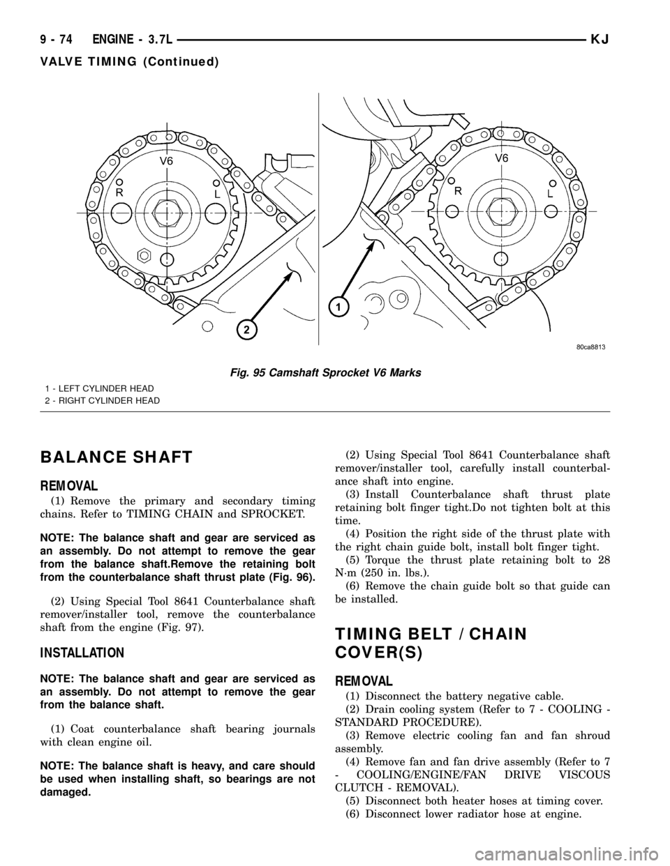
Fig. 95 Camshaft Sprocket V6 Marks
1 - LEFT CYLINDER HEAD
2 - RIGHT CYLINDER HEAD
9 - 74 ENGINE - 3.7LKJ
VALVE TIMING (Continued)
Page 1290 of 1803
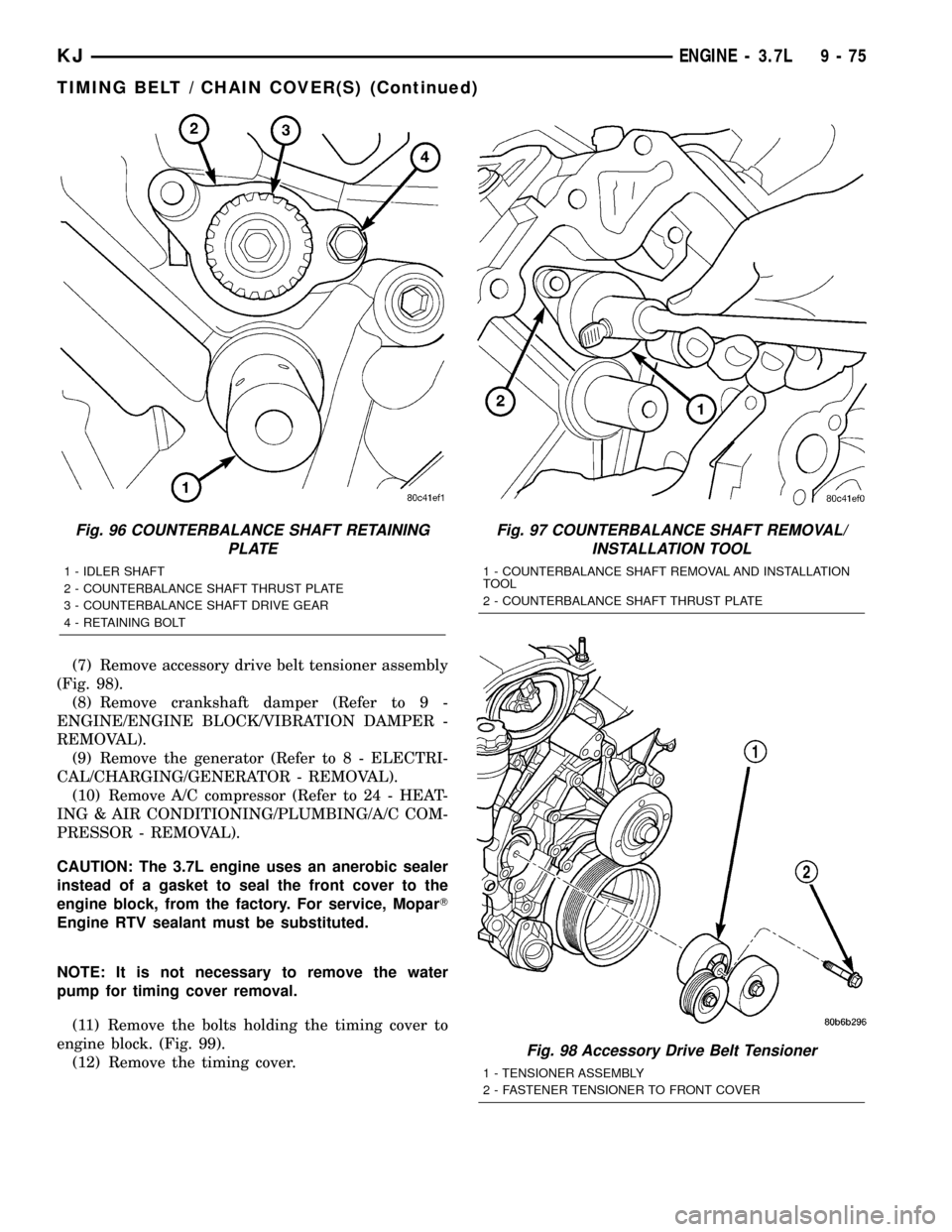
(7) Remove accessory drive belt tensioner assembly
(Fig. 98).
(8) Remove crankshaft damper (Refer to 9 -
ENGINE/ENGINE BLOCK/VIBRATION DAMPER -
REMOVAL).
(9) Remove the generator (Refer to 8 - ELECTRI-
CAL/CHARGING/GENERATOR - REMOVAL).
(10) Remove A/C compressor (Refer to 24 - HEAT-
ING & AIR CONDITIONING/PLUMBING/A/C COM-
PRESSOR - REMOVAL).
CAUTION: The 3.7L engine uses an anerobic sealer
instead of a gasket to seal the front cover to the
engine block, from the factory. For service, MoparT
Engine RTV sealant must be substituted.
NOTE: It is not necessary to remove the water
pump for timing cover removal.
(11) Remove the bolts holding the timing cover to
engine block. (Fig. 99).
(12) Remove the timing cover.
Fig. 96 COUNTERBALANCE SHAFT RETAINING
PLATE
1 - IDLER SHAFT
2 - COUNTERBALANCE SHAFT THRUST PLATE
3 - COUNTERBALANCE SHAFT DRIVE GEAR
4 - RETAINING BOLT
Fig. 97 COUNTERBALANCE SHAFT REMOVAL/
INSTALLATION TOOL
1 - COUNTERBALANCE SHAFT REMOVAL AND INSTALLATION
TOOL
2 - COUNTERBALANCE SHAFT THRUST PLATE
Fig. 98 Accessory Drive Belt Tensioner
1 - TENSIONER ASSEMBLY
2 - FASTENER TENSIONER TO FRONT COVER
KJENGINE - 3.7L 9 - 75
TIMING BELT / CHAIN COVER(S) (Continued)
Page 1292 of 1803
IDLER SHAFT
REMOVAL
(1) Remove the primary and secondary timing
chains and sprockets. Refer to procedure in this sec-
tion.
NOTE: To remove the idler shaft, it is necessary to
tap threads into the shaft, to install the removal
tool.
(2) Using a 12 mm X 1.75 tap, cut threads in the
idler shaft center bore.
(3) Cover the radiator core with a suitable cover.
CAUTION: Use care when removing the idler shaft,
Do not strike the radiator cooling fins with the slide
hammer.
(4) Using Special Tool 8517 Slide Hammer, remove
the idler shaft.
INSTALLATION
(1) Thoroughly clean the idler shaft bore.
(2) Position the idler shaft in the bore.
NOTE: The two lubrication holes in the idler shaft
do not require any special alignment.
NOTE: Before using the retaining bolt to install the
idler shaft, coat the threads and the pilot on the
idler shaft, with clean engine oil.
(3) Using the primary idler sprocket retaining bolt
and washer, carefully draw the idler shaft into the
bore until fully seated.
(4) Coat the idler shaft with clean engine oil.
(5) Install the timing chains and sprockets. Refer
to procedure in this section.
TIMING BELT/CHAIN AND
SPROCKET(S
REMOVAL
(1) Disconnect negative cable from battery.
(2) Drain cooling system. Refer to COOLING SYS-
TEM for procedures.
(3) Remove right and left cylinder head covers.
Refer to CYLINDER HEAD COVER.
(4) Remove radiator fan shroud. Refer to COOL-
ING SYSTEM for procedure.
(5) Rotate engine until timing mark on crankshaft
damper aligns with TDC mark on timing chain cover
(Fig. 103) (#1 cylinder exhaust stroke) and the cam-
shaft sprocket ªV6º marks are at the 12 o'clock posi-
tion (Fig. 102).
CAUTION: The nut on the right side camshaft
sprocket should not be removed for any reason, as
the sprocket and camshaft sensor target wheel is
serviced as an assembly. If the nut was removed
retorque nut to 5 N´m (44 in. lbs.).
(6) Remove power steering pump. Refer to STEER-
ING for procedure.
(7) Remove access plug from left and right cylinder
heads for access to chain guide fasteners (Fig. 104).
(8) Remove the oil fill housing to gain access to the
right side tensioner arm fastener.
(9) Remove crankshaft damper and timing chain
cover. Refer to procedures.
(10) Collapse and pin primary chain tensioner.
CAUTION: Plate behind left secondary chain ten-
sioner could fall into oil pan. Therefore, cover pan
opening.
(11) Remove secondary chain tensioners.
(12) Remove camshaft position and crankshaft
position sensors (Fig. 105) and (Fig. 106).
KJENGINE - 3.7L 9 - 77
Page 1298 of 1803
ENGINE
TABLE OF CONTENTS
page page
ENGINE - 2.4L
DESCRIPTION..........................3
DIAGNOSIS AND TESTING
DIAGNOSIS AND TESTING - CYLINDER
COMBUSTION PRESSURE LEAKAGE
TEST................................3
DIAGNOSIS AND TESTING - CYLINDER
COMPRESSION PRESSURE TEST.........3
DIAGNOSIS AND TESTING - ENGINE OIL
LEAK INSPECTION.....................4
DIAGNOSIS AND TESTING - ENGINE.......5
DIAGNOSIS AND TESTING - ENGINE
DIAGNOSIS - PERFORMANCE............5
DIAGNOSIS AND TESTING - ENGINE
MECHANICAL.........................7
STANDARD PROCEDURE
STANDARD PROCEDURE - ENGINE CORE
AND OIL GALLERY PLUGS...............9
STANDARD PROCEDURE - REPAIR OF
DAMAGED OR WORN THREADS..........9
STANDARD PROCEDURE - HYDROSTATIC
LOCKED ENGINE......................9
STANDARD PROCEDURE - FORM-IN-
PLACE GASKETS AND SEALERS.........10
STANDARD PROCEDURE - ENGINE
GASKET SURFACE PREPARATION........11
STANDARD PROCEDURE - MEASURING
BEARING CLEARANCE USING
PLASTIGAGE.........................11
REMOVAL - ENGINE ASSEMBLY...........12
INSTALLATION - ENGINE ASSEMBLY........12
SPECIFICATIONS
SPECIFICATIONS - 2.4L ENGINE.........13
SPECIFICATIONS - TORQUE............16
SPECIAL TOOLS
2.4L ENGINE.........................17
AIR CLEANER ELEMENT
REMOVAL - 2.4L........................19
INSTALLATION - 2.4L....................19
CYLINDER HEAD
DESCRIPTION.........................19
OPERATION...........................19
DIAGNOSIS AND TESTING - CYLINDER HEAD
GASKET............................19
REMOVAL - CYLINDER HEAD.............20
CLEANING............................20
INSPECTION..........................21
INSTALLATION - CYLINDER HEAD..........21CAMSHAFT OIL SEAL(S)
REMOVAL.............................22
INSTALLATION.........................22
CAMSHAFT(S)
DESCRIPTION.........................23
OPERATION...........................23
STANDARD PROCEDURE - CAMSHAFT
END-PLAY...........................23
REMOVAL.............................24
CLEANING............................24
INSPECTION..........................25
INSTALLATION.........................25
CYLINDER HEAD COVER
REMOVAL.............................26
CLEANING............................26
INSPECTION..........................26
INSTALLATION.........................26
INTAKE/EXHAUST VALVES & SEATS
DESCRIPTION.........................27
CLEANING............................27
VALVE SPRINGS
REMOVAL
REMOVAL - CYLINDER HEAD ON.........27
REMOVAL - CYLINDER HEAD OFF........27
INSPECTION..........................28
INSTALLATION
INSTALLATION - CYLINDER HEAD ON.....28
INSTALLATION - CYLINDER HEAD OFF....28
HYDRAULIC LIFTERS
DIAGNOSIS AND TESTING - LASH ADJUSTER
(TAPPET) NOISE DIAGNOSIS............28
REMOVAL.............................29
INSTALLATION.........................29
ROCKER ARMS
REMOVAL.............................29
INSPECTION..........................30
INSTALLATION.........................30
ENGINE BLOCK
DESCRIPTION.........................30
STANDARD PROCEDURE
STANDARD PROCEDURE - PISTON TO
CYLINDER BORE FITTING..............30
STANDARD PROCEDURE - CYLINDER
BORE HONING.......................31
CLEANING............................31
INSPECTION..........................32
CONNECTING ROD BEARINGS
STANDARD PROCEDURE
CONNECTING ROD - FITTING...........32
KJENGINE 9s - 1
Page 1299 of 1803
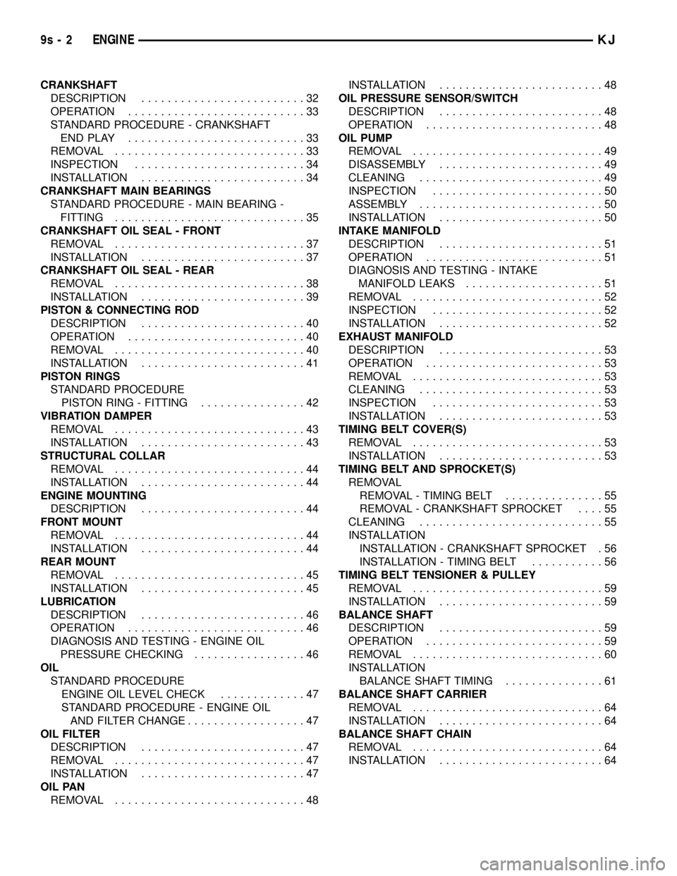
CRANKSHAFT
DESCRIPTION.........................32
OPERATION...........................33
STANDARD PROCEDURE - CRANKSHAFT
ENDPLAY ...........................33
REMOVAL.............................33
INSPECTION..........................34
INSTALLATION.........................34
CRANKSHAFT MAIN BEARINGS
STANDARD PROCEDURE - MAIN BEARING -
FITTING.............................35
CRANKSHAFT OIL SEAL - FRONT
REMOVAL.............................37
INSTALLATION.........................37
CRANKSHAFT OIL SEAL - REAR
REMOVAL.............................38
INSTALLATION.........................39
PISTON & CONNECTING ROD
DESCRIPTION.........................40
OPERATION...........................40
REMOVAL.............................40
INSTALLATION.........................41
PISTON RINGS
STANDARD PROCEDURE
PISTON RING - FITTING................42
VIBRATION DAMPER
REMOVAL.............................43
INSTALLATION.........................43
STRUCTURAL COLLAR
REMOVAL.............................44
INSTALLATION.........................44
ENGINE MOUNTING
DESCRIPTION.........................44
FRONT MOUNT
REMOVAL.............................44
INSTALLATION.........................44
REAR MOUNT
REMOVAL.............................45
INSTALLATION.........................45
LUBRICATION
DESCRIPTION.........................46
OPERATION...........................46
DIAGNOSIS AND TESTING - ENGINE OIL
PRESSURE CHECKING.................46
OIL
STANDARD PROCEDURE
ENGINE OIL LEVEL CHECK.............47
STANDARD PROCEDURE - ENGINE OIL
AND FILTER CHANGE..................47
OIL FILTER
DESCRIPTION.........................47
REMOVAL.............................47
INSTALLATION.........................47
OIL PAN
REMOVAL.............................48INSTALLATION.........................48
OIL PRESSURE SENSOR/SWITCH
DESCRIPTION.........................48
OPERATION...........................48
OIL PUMP
REMOVAL.............................49
DISASSEMBLY.........................49
CLEANING............................49
INSPECTION..........................50
ASSEMBLY............................50
INSTALLATION.........................50
INTAKE MANIFOLD
DESCRIPTION.........................51
OPERATION...........................51
DIAGNOSIS AND TESTING - INTAKE
MANIFOLD LEAKS.....................51
REMOVAL.............................52
INSPECTION..........................52
INSTALLATION.........................52
EXHAUST MANIFOLD
DESCRIPTION.........................53
OPERATION...........................53
REMOVAL.............................53
CLEANING............................53
INSPECTION..........................53
INSTALLATION.........................53
TIMING BELT COVER(S)
REMOVAL.............................53
INSTALLATION.........................53
TIMING BELT AND SPROCKET(S)
REMOVAL
REMOVAL - TIMING BELT...............55
REMOVAL - CRANKSHAFT SPROCKET....55
CLEANING............................55
INSTALLATION
INSTALLATION - CRANKSHAFT SPROCKET . 56
INSTALLATION - TIMING BELT...........56
TIMING BELT TENSIONER & PULLEY
REMOVAL.............................59
INSTALLATION.........................59
BALANCE SHAFT
DESCRIPTION.........................59
OPERATION...........................59
REMOVAL.............................60
INSTALLATION
BALANCE SHAFT TIMING...............61
BALANCE SHAFT CARRIER
REMOVAL.............................64
INSTALLATION.........................64
BALANCE SHAFT CHAIN
REMOVAL.............................64
INSTALLATION.........................64
9s - 2 ENGINEKJ
Page 1306 of 1803
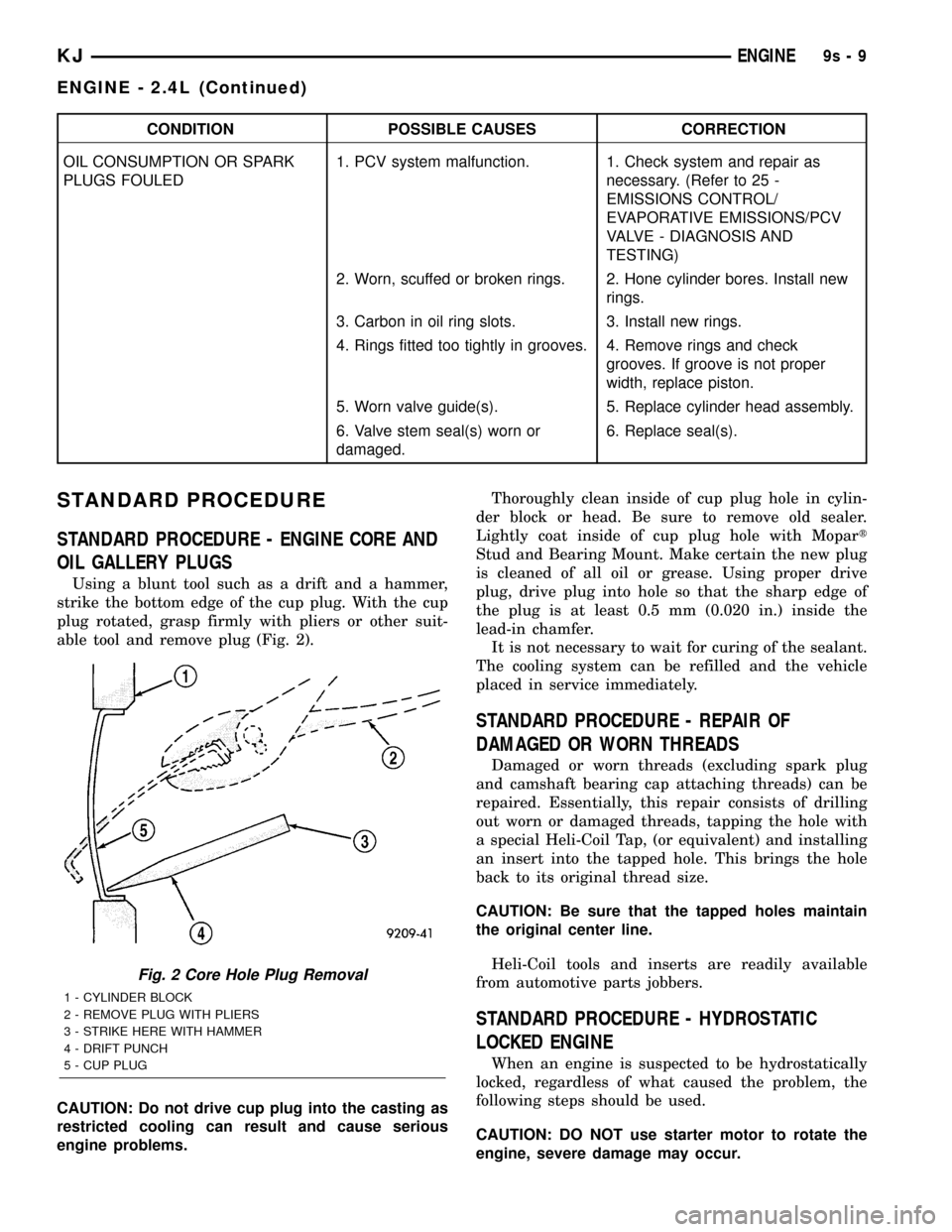
CONDITION POSSIBLE CAUSES CORRECTION
OIL CONSUMPTION OR SPARK
PLUGS FOULED1. PCV system malfunction. 1. Check system and repair as
necessary. (Refer to 25 -
EMISSIONS CONTROL/
EVAPORATIVE EMISSIONS/PCV
VALVE - DIAGNOSIS AND
TESTING)
2. Worn, scuffed or broken rings. 2. Hone cylinder bores. Install new
rings.
3. Carbon in oil ring slots. 3. Install new rings.
4. Rings fitted too tightly in grooves. 4. Remove rings and check
grooves. If groove is not proper
width, replace piston.
5. Worn valve guide(s). 5. Replace cylinder head assembly.
6. Valve stem seal(s) worn or
damaged.6. Replace seal(s).
STANDARD PROCEDURE
STANDARD PROCEDURE - ENGINE CORE AND
OIL GALLERY PLUGS
Using a blunt tool such as a drift and a hammer,
strike the bottom edge of the cup plug. With the cup
plug rotated, grasp firmly with pliers or other suit-
able tool and remove plug (Fig. 2).
CAUTION: Do not drive cup plug into the casting as
restricted cooling can result and cause serious
engine problems.Thoroughly clean inside of cup plug hole in cylin-
der block or head. Be sure to remove old sealer.
Lightly coat inside of cup plug hole with Mopart
Stud and Bearing Mount. Make certain the new plug
is cleaned of all oil or grease. Using proper drive
plug, drive plug into hole so that the sharp edge of
the plug is at least 0.5 mm (0.020 in.) inside the
lead-in chamfer.
It is not necessary to wait for curing of the sealant.
The cooling system can be refilled and the vehicle
placed in service immediately.
STANDARD PROCEDURE - REPAIR OF
DAMAGED OR WORN THREADS
Damaged or worn threads (excluding spark plug
and camshaft bearing cap attaching threads) can be
repaired. Essentially, this repair consists of drilling
out worn or damaged threads, tapping the hole with
a special Heli-Coil Tap, (or equivalent) and installing
an insert into the tapped hole. This brings the hole
back to its original thread size.
CAUTION: Be sure that the tapped holes maintain
the original center line.
Heli-Coil tools and inserts are readily available
from automotive parts jobbers.
STANDARD PROCEDURE - HYDROSTATIC
LOCKED ENGINE
When an engine is suspected to be hydrostatically
locked, regardless of what caused the problem, the
following steps should be used.
CAUTION: DO NOT use starter motor to rotate the
engine, severe damage may occur.
Fig. 2 Core Hole Plug Removal
1 - CYLINDER BLOCK
2 - REMOVE PLUG WITH PLIERS
3 - STRIKE HERE WITH HAMMER
4 - DRIFT PUNCH
5 - CUP PLUG
KJENGINE9s-9
ENGINE - 2.4L (Continued)
Page 1309 of 1803
NOTE: Plastigage is available in a variety of clear-
ance ranges. Use the most appropriate range for
the specifications you are checking.
(4) Install the proper crankshaft bearings to
achieve the specified bearing clearances. (Refer to 9 -
ENGINE/ENGINE BLOCK/CRANKSHAFT MAIN
BEARINGS - STANDARD PROCEDURE) (Refer to 9
- ENGINE/ENGINE BLOCK/CONNECTING ROD
BEARINGS - STANDARD PROCEDURE)
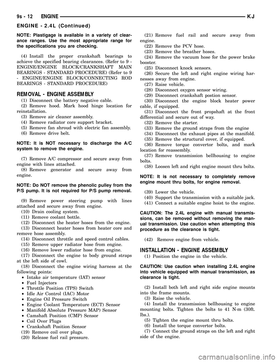
REMOVAL - ENGINE ASSEMBLY
(1) Disconnect the battery negative cable.
(2) Remove hood. Mark hood hinge location for
reinstallation.
(3) Remove air cleaner assembly.
(4) Remove radiator core support bracket.
(5) Remove fan shroud with electric fan assembly.
(6) Remove drive belt.
NOTE: It is NOT necessary to discharge the A/C
system to remove the engine.
(7) Remove A/C compressor and secure away from
engine with lines attached.
(8) Remove generator and secure away from
engine.
NOTE: Do NOT remove the phenolic pulley from the
P/S pump. It is not required for P/S pump removal.
(9) Remove power steering pump with lines
attached and secure away from engine.
(10) Drain cooling system.
(11) Remove coolant bottle.
(12) Disconnect the heater hoses from the engine.
(13) Disconnect heater hoses from heater core and
remove hose assembly.
(14) Disconnect throttle and speed control cables.
(15) Remove upper radiator hose from engine.
(16) Remove lower radiator hose from engine.
(17) Disconnect the engine to body ground straps
at the left side of cowl.
(18) Disconnect the engine wiring harness at the
following points:
²Intake air temperature (IAT) sensor
²Fuel Injectors
²Throttle Position (TPS) Switch
²Idle Air Control (IAC) Motor
²Engine Oil Pressure Switch
²Engine Coolant Temperature (ECT) Sensor
²Manifold Absolute Pressure MAP) Sensor
²Camshaft Position (CMP) Sensor
²Coil Over Plugs
²Crankshaft Position Sensor
(19) Remove coil over plugs.
(20) Release fuel rail pressure.(21) Remove fuel rail and secure away from
engine.
(22) Remove the PCV hose.
(23) Remove the breather hoses.
(24) Remove the vacuum hose for the power brake
booster.
(25) Disconnect knock sensors.
(26) Secure the left and right engine wiring har-
nesses away from engine.
(27) Raise vehicle.
(28) Disconnect oxygen sensor wiring.
(29) Disconnect crankshaft postion sensor.
(30) Disconnect the engine block heater power
cable, if equipped.
(31) Disconnect the front propshaft at the front
differential and secure out of way.
(32) Remove the starter.
(33) Remove the ground straps from the engine
(34) Disconnect the exhaust pipes at the manifold.
(35) Remove the structural cover, if equipped.
(36) Remove torque convertor bolts, and mark
location for reassembly.
(37) Remove transmission bellhousing to engine
bolts.
(38) Loosen left and right engine mount thru bolts.
NOTE: It is not necessary to completely remove
engine mount thru bolts, for engine removal.
(39) Lower the vehicle.
(40) Support the transmission with a suitable jack.
(41) Connect a suitable engine hoist to the engine.
CAUTION: The 2.4L engine with manual transmis-
sions, can be removed without removing the man-
ual transmission. Use caution when attempting this
procedure as the clearance is tight.
(42) Remove engine from vehicle.
INSTALLATION - ENGINE ASSEMBLY
(1) Position the engine in the vehicle.
CAUTION: Use caution when installing 2.4L engine
into vehicle equipped with manual transmission, as
clearance is tight.
(2) Install both left and right side engine mounts
into the frame mounts.
(3) Raise the vehicle.
(4) Install the transmission bellhousing to engine
mounting bolts. Tighten the bolts to 41 N´m (30ft.
lbs.).
(5) Tighten the engine mount thru bolts.
(6) Install the torque convertor bolts.
(7) Connect the ground straps on the left and right
side of the engine.
9s - 12 ENGINEKJ
ENGINE - 2.4L (Continued)
Page 1314 of 1803
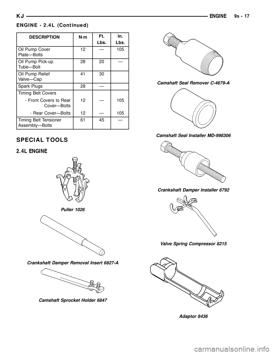
DESCRIPTION N´mFt.
Lbs.In.
Lbs.
Oil Pump Cover
PlateÐBolts12 Ð 105
Oil Pump Pick-up
TubeÐBolt28 20 Ð
Oil Pump Relief
ValveÐCap41 30
Spark Plugs 28 Ð
Timing Belt Covers
- Front Covers to Rear
CoverÐBolts12 Ð 105
- Rear CoverÐBolts 12 Ð 105
Timing Belt Tensioner
AssemblyÐBolts61 45 Ð
SPECIAL TOOLS
2.4L ENGINE
Puller 1026
Crankshaft Damper Removal Insert 6827-A
Camshaft Sprocket Holder 6847
Camshaft Seal Remover C-4679-A
Camshaft Seal Installer MD-998306
Crankshaft Damper Installer 6792
Valve Spring Compressor 8215
Adaptor 8436
KJENGINE9s-17
ENGINE - 2.4L (Continued)