2002 JEEP LIBERTY Engine removal
[x] Cancel search: Engine removalPage 1272 of 1803
INSTALLATION
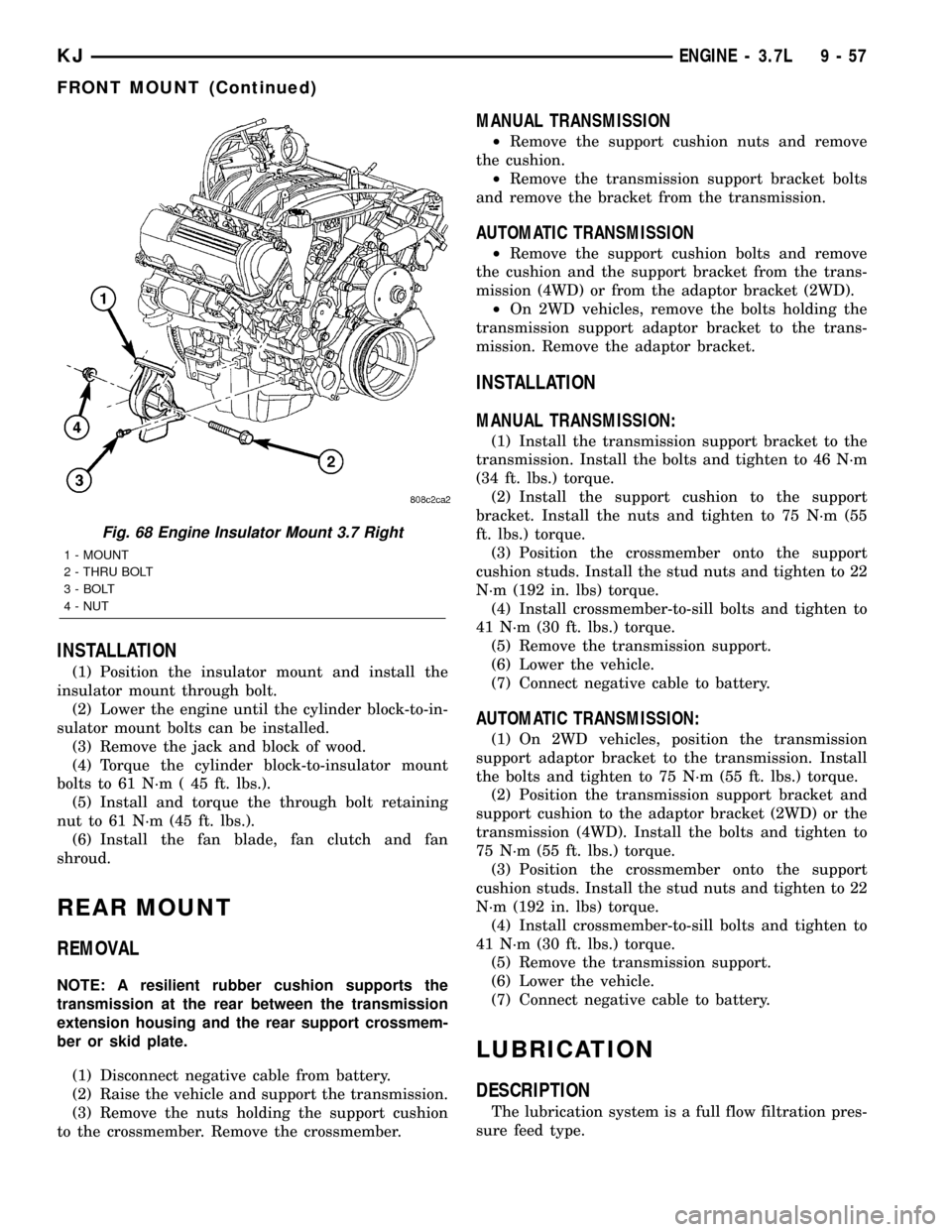
(1) Position the insulator mount and install the
insulator mount through bolt.
(2) Lower the engine until the cylinder block-to-in-
sulator mount bolts can be installed.
(3) Remove the jack and block of wood.
(4) Torque the cylinder block-to-insulator mount
bolts to 61 N´m ( 45 ft. lbs.).
(5) Install and torque the through bolt retaining
nut to 61 N´m (45 ft. lbs.).
(6) Install the fan blade, fan clutch and fan
shroud.
REAR MOUNT
REMOVAL
NOTE: A resilient rubber cushion supports the
transmission at the rear between the transmission
extension housing and the rear support crossmem-
ber or skid plate.
(1) Disconnect negative cable from battery.
(2) Raise the vehicle and support the transmission.
(3) Remove the nuts holding the support cushion
to the crossmember. Remove the crossmember.
MANUAL TRANSMISSION
²Remove the support cushion nuts and remove
the cushion.
²Remove the transmission support bracket bolts
and remove the bracket from the transmission.
AUTOMATIC TRANSMISSION
²Remove the support cushion bolts and remove
the cushion and the support bracket from the trans-
mission (4WD) or from the adaptor bracket (2WD).
²On 2WD vehicles, remove the bolts holding the
transmission support adaptor bracket to the trans-
mission. Remove the adaptor bracket.
INSTALLATION
MANUAL TRANSMISSION:
(1) Install the transmission support bracket to the
transmission. Install the bolts and tighten to 46 N´m
(34 ft. lbs.) torque.
(2) Install the support cushion to the support
bracket. Install the nuts and tighten to 75 N´m (55
ft. lbs.) torque.
(3) Position the crossmember onto the support
cushion studs. Install the stud nuts and tighten to 22
N´m (192 in. lbs) torque.
(4) Install crossmember-to-sill bolts and tighten to
41 N´m (30 ft. lbs.) torque.
(5) Remove the transmission support.
(6) Lower the vehicle.
(7) Connect negative cable to battery.
AUTOMATIC TRANSMISSION:
(1) On 2WD vehicles, position the transmission
support adaptor bracket to the transmission. Install
the bolts and tighten to 75 N´m (55 ft. lbs.) torque.
(2) Position the transmission support bracket and
support cushion to the adaptor bracket (2WD) or the
transmission (4WD). Install the bolts and tighten to
75 N´m (55 ft. lbs.) torque.
(3) Position the crossmember onto the support
cushion studs. Install the stud nuts and tighten to 22
N´m (192 in. lbs) torque.
(4) Install crossmember-to-sill bolts and tighten to
41 N´m (30 ft. lbs.) torque.
(5) Remove the transmission support.
(6) Lower the vehicle.
(7) Connect negative cable to battery.
LUBRICATION
DESCRIPTION
The lubrication system is a full flow filtration pres-
sure feed type.
Fig. 68 Engine Insulator Mount 3.7 Right
1 - MOUNT
2 - THRU BOLT
3 - BOLT
4 - NUT
KJENGINE - 3.7L 9 - 57
FRONT MOUNT (Continued)
Page 1276 of 1803
DIAGNOSIS AND TESTING - REAR SEAL AREA
LEAKS
Since it is sometimes difficult to determine the
source of an oil leak in the rear seal area of the
engine, a more involved inspection is necessary. The
following steps should be followed to help pinpoint
the source of the leak.
If the leakage occurs at the crankshaft rear oil seal
area:
(1) Disconnect the battery.
(2) Raise the vehicle.
(3) Remove torque converter or clutch housing
cover and inspect rear of block for evidence of oil.
Use a black light to check for the oil leak:
(a) Circular spray pattern generally indicates
seal leakage or crankshaft damage.
(b) Where leakage tends to run straight down,
possible causes are a porous block, camshaft bore
cup plugs, oil galley pipe plugs, oil filter runoff,
and main bearing cap to cylinder block mating sur-
faces. See Engine, for proper repair procedures of
these items.
(4) If no leaks are detected, pressurized the crank-
case as outlined in the section, Inspection (Engine oil
Leaks in general)
CAUTION: Do not exceed 20.6 kPa (3 psi).(5) If the leak is not detected, very slowly turn the
crankshaft and watch for leakage. If a leak is
detected between the crankshaft and seal while
slowly turning the crankshaft, it is possible the
crankshaft seal surface is damaged. The seal area on
the crankshaft could have minor nicks or scratches
that can be polished out with emery cloth.
CAUTION: Use extreme caution when crankshaft
polishing is necessary to remove minor nicks or
scratches. The crankshaft seal flange is specially
machined to complement the function of the rear oil
seal.
(6) For bubbles that remain steady with shaft
rotation, no further inspection can be done until dis-
assembled. (Refer to 9 - ENGINE - DIAGNOSIS AND
TESTING), under the Oil Leak row, for components
inspections on possible causes and corrections.
(7) After the oil leak root cause and appropriate
corrective action have been identified, (Refer to 9 -
ENGINE/ENGINE BLOCK/CRANKSHAFT OIL
SEAL - REAR - REMOVAL).
OIL
STANDARD PROCEDURE - ENGINE OIL
WARNING: NEW OR USED ENGINE OIL CAN BE
IRRITATING TO THE SKIN. AVOID PROLONGED OR
REPEATED SKIN CONTACT WITH ENGINE OIL.
CONTAMINANTS IN USED ENGINE OIL, CAUSED BY
INTERNAL COMBUSTION, CAN BE HAZARDOUS TO
YOUR HEALTH. THOROUGHLY WASH EXPOSED
SKIN WITH SOAP AND WATER. DO NOT WASH
SKIN WITH GASOLINE, DIESEL FUEL, THINNER, OR
SOLVENTS, HEALTH PROBLEMS CAN RESULT. DO
NOT POLLUTE, DISPOSE OF USED ENGINE OIL
PROPERLY.
ENGINE OIL SPECIFICATION
CAUTION: Do not use non-detergent or straight
mineral oil when adding or changing crankcase
lubricant. Engine failure can result.
API SERVICE GRADE CERTIFIED
Use an engine oil that is API Service Grade Certi-
fied. MOPARtprovides engine oils that conform to
this service grade.
SAE VISCOSITY
An SAE viscosity grade is used to specify the vis-
cosity of engine oil. Use only engine oils with multi-
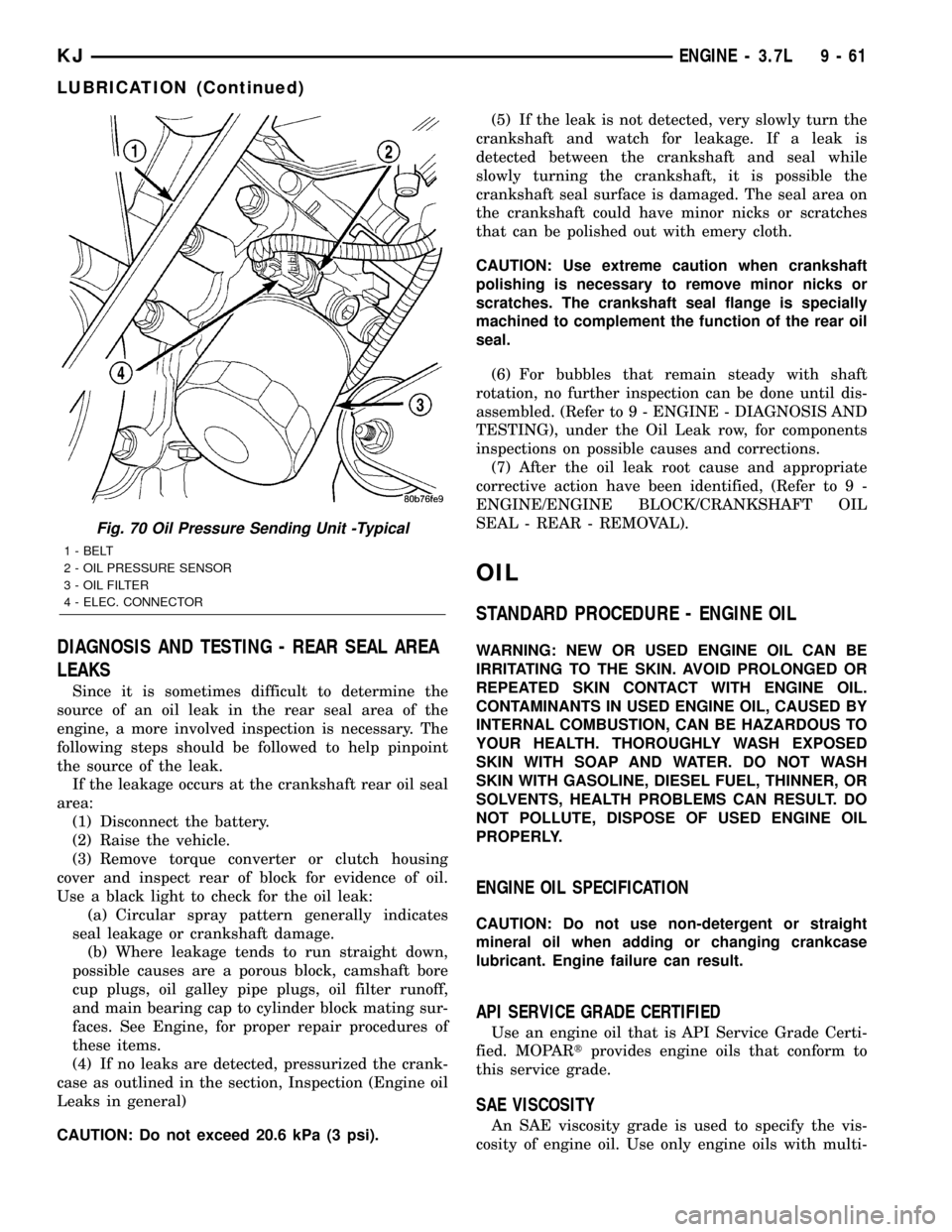
Fig. 70 Oil Pressure Sending Unit -Typical
1 - BELT
2 - OIL PRESSURE SENSOR
3 - OIL FILTER
4 - ELEC. CONNECTOR
KJENGINE - 3.7L 9 - 61
LUBRICATION (Continued)
Page 1277 of 1803
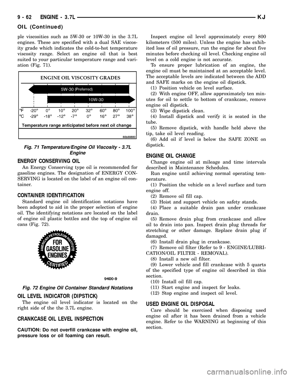
ple viscosities such as 5W-30 or 10W-30 in the 3.7L
engines. These are specified with a dual SAE viscos-
ity grade which indicates the cold-to-hot temperature
viscosity range. Select an engine oil that is best
suited to your particular temperature range and vari-
ation (Fig. 71).
ENERGY CONSERVING OIL
An Energy Conserving type oil is recommended for
gasoline engines. The designation of ENERGY CON-
SERVING is located on the label of an engine oil con-
tainer.
CONTAINER IDENTIFICATION
Standard engine oil identification notations have
been adopted to aid in the proper selection of engine
oil. The identifying notations are located on the label
of engine oil plastic bottles and the top of engine oil
cans (Fig. 72).
OIL LEVEL INDICATOR (DIPSTICK)
The engine oil level indicator is located on the
right side of the the 3.7L engine.
CRANKCASE OIL LEVEL INSPECTION
CAUTION: Do not overfill crankcase with engine oil,
pressure loss or oil foaming can result.Inspect engine oil level approximately every 800
kilometers (500 miles). Unless the engine has exhib-
ited loss of oil pressure, run the engine for about five
minutes before checking oil level. Checking engine oil
level on a cold engine is not accurate.
To ensure proper lubrication of an engine, the
engine oil must be maintained at an acceptable level.
The acceptable levels are indicated between the ADD
and SAFE marks on the engine oil dipstick.
(1) Position vehicle on level surface.
(2) With engine OFF, allow approximately ten min-
utes for oil to settle to bottom of crankcase, remove
engine oil dipstick.
(3) Wipe dipstick clean.
(4) Install dipstick and verify it is seated in the
tube.
(5) Remove dipstick, with handle held above the
tip, take oil level reading.
(6) Add oil if level is below the SAFE ZONE on
dipstick.
ENGINE OIL CHANGE
Change engine oil at mileage and time intervals
described in Maintenance Schedules.
Run engine until achieving normal operating tem-
perature.
(1) Position the vehicle on a level surface and turn
engine off.
(2) Remove oil fill cap.
(3) Hoist and support vehicle on safety stands.
(4) Place a suitable drain pan under crankcase
drain.
(5) Remove drain plug from crankcase and allow
oil to drain into pan. Inspect drain plug threads for
stretching or other damage. Replace drain plug if
damaged.
(6) Install drain plug in crankcase.
(7) Remove oil filter (Refer to 9 - ENGINE/LUBRI-
CATION/OIL FILTER - REMOVAL).
(8) Install a new oil filter.
(9) Lower vehicle and fill crankcase with 5 quarts
of the specified type of engine oil described in this
section.
(10) Install oil fill cap.
(11) Start engine and inspect for leaks.
(12) Stop engine and inspect oil level.
USED ENGINE OIL DISPOSAL
Care should be exercised when disposing used
engine oil after it has been drained from a vehicle
engine. Refer to the WARNING at beginning of this
section.
Fig. 71 Temperature/Engine Oil Viscosity - 3.7L
Engine
Fig. 72 Engine Oil Container Standard Notations
9 - 62 ENGINE - 3.7LKJ
OIL (Continued)
Page 1278 of 1803
OIL FILTER
REMOVAL
All engines are equipped with a high quality full-
flow, disposable type oil filter. DaimlerChrysler Cor-
poration recommends a Mopartor equivalent oil
filter be used.
(1) Position a drain pan under the oil filter.
(2) Using a suitable oil filter wrench loosen filter.
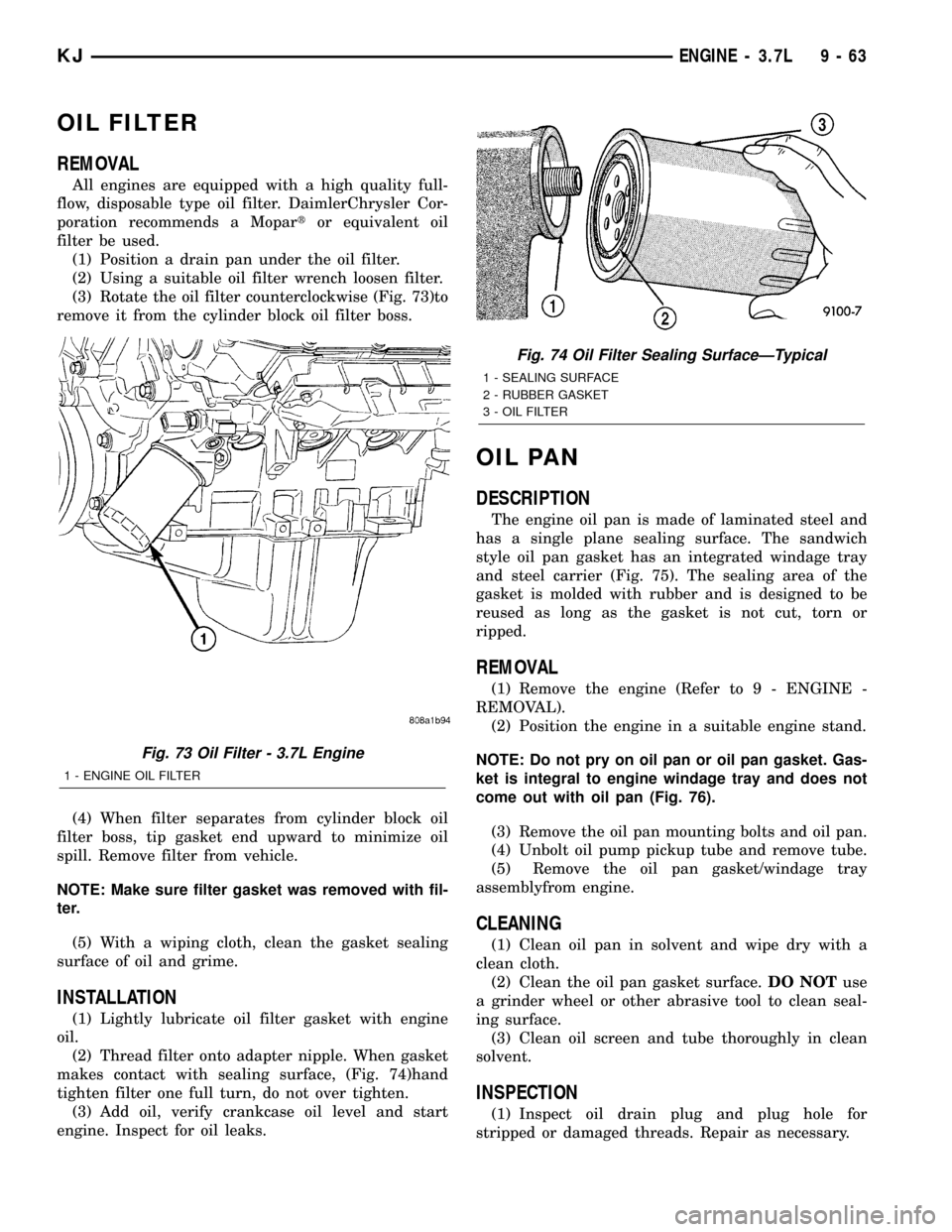
(3) Rotate the oil filter counterclockwise (Fig. 73)to
remove it from the cylinder block oil filter boss.
(4) When filter separates from cylinder block oil
filter boss, tip gasket end upward to minimize oil
spill. Remove filter from vehicle.
NOTE: Make sure filter gasket was removed with fil-
ter.
(5) With a wiping cloth, clean the gasket sealing
surface of oil and grime.
INSTALLATION
(1) Lightly lubricate oil filter gasket with engine
oil.
(2) Thread filter onto adapter nipple. When gasket
makes contact with sealing surface, (Fig. 74)hand
tighten filter one full turn, do not over tighten.
(3) Add oil, verify crankcase oil level and start
engine. Inspect for oil leaks.
OIL PAN
DESCRIPTION
The engine oil pan is made of laminated steel and
has a single plane sealing surface. The sandwich
style oil pan gasket has an integrated windage tray
and steel carrier (Fig. 75). The sealing area of the
gasket is molded with rubber and is designed to be
reused as long as the gasket is not cut, torn or
ripped.
REMOVAL
(1) Remove the engine (Refer to 9 - ENGINE -
REMOVAL).
(2) Position the engine in a suitable engine stand.
NOTE: Do not pry on oil pan or oil pan gasket. Gas-
ket is integral to engine windage tray and does not
come out with oil pan (Fig. 76).
(3) Remove the oil pan mounting bolts and oil pan.
(4) Unbolt oil pump pickup tube and remove tube.
(5) Remove the oil pan gasket/windage tray
assemblyfrom engine.
CLEANING
(1) Clean oil pan in solvent and wipe dry with a
clean cloth.
(2) Clean the oil pan gasket surface.DO NOTuse
a grinder wheel or other abrasive tool to clean seal-
ing surface.
(3) Clean oil screen and tube thoroughly in clean
solvent.
INSPECTION
(1) Inspect oil drain plug and plug hole for
stripped or damaged threads. Repair as necessary.
Fig. 73 Oil Filter - 3.7L Engine
1 - ENGINE OIL FILTER
Fig. 74 Oil Filter Sealing SurfaceÐTypical
1 - SEALING SURFACE
2 - RUBBER GASKET
3 - OIL FILTER
KJENGINE - 3.7L 9 - 63
Page 1280 of 1803
OIL PRESSURE SENSOR/
SWITCH
DESCRIPTION
The 3±wire, solid-state engine oil pressure sensor
(sending unit) is located in an engine oil pressure
gallery.
OPERATION
The oil pressure sensor uses three circuits. They
are:
²A 5±volt power supply from the Powertrain Con-
trol Module (PCM)
²A sensor ground through the PCM's sensor
return
²A signal to the PCM relating to engine oil pres-
sure
The oil pressure sensor has a 3±wire electrical
function very much like the Manifold Absolute Pres-
sure (MAP) sensor. Meaning different pressures
relate to different output voltages.
A 5±volt supply is sent to the sensor from the PCM
to power up the sensor. The sensor returns a voltage
signal back to the PCM relating to engine oil pres-
sure. This signal is then transferred (bussed) to the
instrument panel on either a CCD or PCI bus circuit
(depending on vehicle line) to operate the oil pressure
gauge and the check gauges lamp. Ground for the
sensor is provided by the PCM through a low-noise
sensor return.
REMOVAL
(1) Disconnect the negative cable from the battery.
(2) Raise vehicle on hoist.
(3) Remove front splash shield.
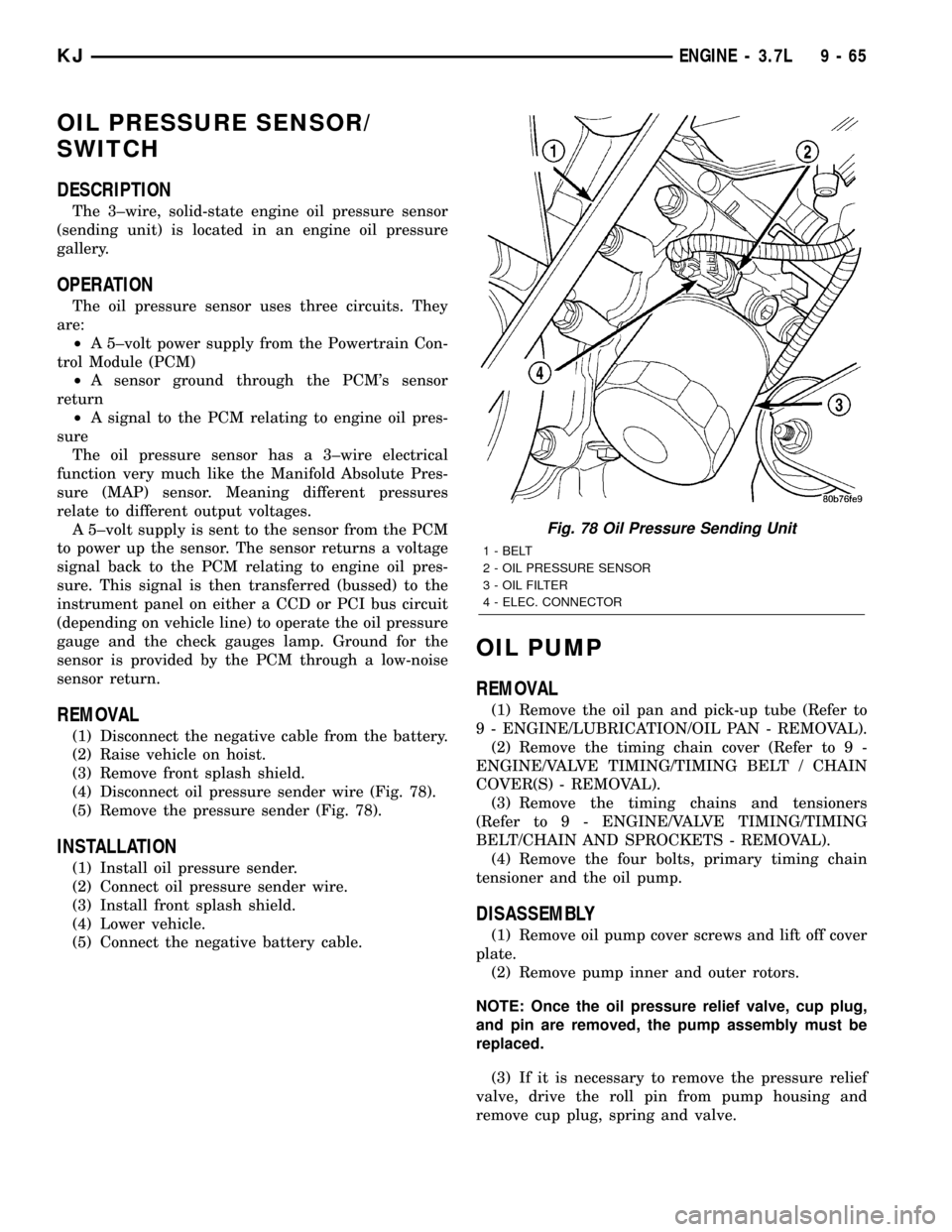
(4) Disconnect oil pressure sender wire (Fig. 78).
(5) Remove the pressure sender (Fig. 78).
INSTALLATION
(1) Install oil pressure sender.
(2) Connect oil pressure sender wire.
(3) Install front splash shield.
(4) Lower vehicle.
(5) Connect the negative battery cable.
OIL PUMP
REMOVAL
(1) Remove the oil pan and pick-up tube (Refer to
9 - ENGINE/LUBRICATION/OIL PAN - REMOVAL).
(2) Remove the timing chain cover (Refer to 9 -
ENGINE/VALVE TIMING/TIMING BELT / CHAIN
COVER(S) - REMOVAL).
(3) Remove the timing chains and tensioners
(Refer to 9 - ENGINE/VALVE TIMING/TIMING
BELT/CHAIN AND SPROCKETS - REMOVAL).
(4) Remove the four bolts, primary timing chain
tensioner and the oil pump.
DISASSEMBLY
(1) Remove oil pump cover screws and lift off cover
plate.
(2) Remove pump inner and outer rotors.
NOTE: Once the oil pressure relief valve, cup plug,
and pin are removed, the pump assembly must be
replaced.
(3) If it is necessary to remove the pressure relief
valve, drive the roll pin from pump housing and
remove cup plug, spring and valve.
Fig. 78 Oil Pressure Sending Unit
1 - BELT
2 - OIL PRESSURE SENSOR
3 - OIL FILTER
4 - ELEC. CONNECTOR
KJENGINE - 3.7L 9 - 65
Page 1283 of 1803
INTAKE MANIFOLD
DESCRIPTION
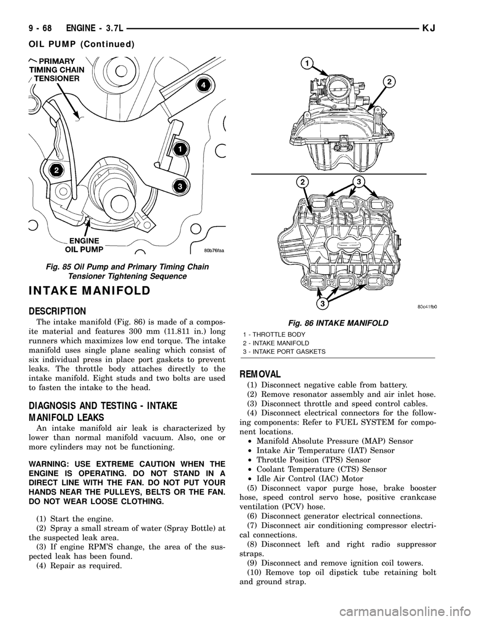
The intake manifold (Fig. 86) is made of a compos-
ite material and features 300 mm (11.811 in.) long
runners which maximizes low end torque. The intake
manifold uses single plane sealing which consist of
six individual press in place port gaskets to prevent
leaks. The throttle body attaches directly to the
intake manifold. Eight studs and two bolts are used
to fasten the intake to the head.
DIAGNOSIS AND TESTING - INTAKE
MANIFOLD LEAKS
An intake manifold air leak is characterized by
lower than normal manifold vacuum. Also, one or
more cylinders may not be functioning.
WARNING: USE EXTREME CAUTION WHEN THE
ENGINE IS OPERATING. DO NOT STAND IN A
DIRECT LINE WITH THE FAN. DO NOT PUT YOUR
HANDS NEAR THE PULLEYS, BELTS OR THE FAN.
DO NOT WEAR LOOSE CLOTHING.
(1) Start the engine.
(2) Spray a small stream of water (Spray Bottle) at
the suspected leak area.
(3) If engine RPM'S change, the area of the sus-
pected leak has been found.
(4) Repair as required.
REMOVAL
(1) Disconnect negative cable from battery.
(2) Remove resonator assembly and air inlet hose.
(3) Disconnect throttle and speed control cables.
(4) Disconnect electrical connectors for the follow-
ing components: Refer to FUEL SYSTEM for compo-
nent locations.
²Manifold Absolute Pressure (MAP) Sensor
²Intake Air Temperature (IAT) Sensor
²Throttle Position (TPS) Sensor
²Coolant Temperature (CTS) Sensor
²Idle Air Control (IAC) Motor
(5) Disconnect vapor purge hose, brake booster
hose, speed control servo hose, positive crankcase
ventilation (PCV) hose.
(6) Disconnect generator electrical connections.
(7) Disconnect air conditioning compressor electri-
cal connections.
(8) Disconnect left and right radio suppressor
straps.
(9) Disconnect and remove ignition coil towers.
(10) Remove top oil dipstick tube retaining bolt
and ground strap.
Fig. 85 Oil Pump and Primary Timing Chain
Tensioner Tightening Sequence
Fig. 86 INTAKE MANIFOLD
1 - THROTTLE BODY
2 - INTAKE MANIFOLD
3 - INTAKE PORT GASKETS
9 - 68 ENGINE - 3.7LKJ
OIL PUMP (Continued)
Page 1284 of 1803
(11) Bleed fuel system. Refer to FUEL SYSTEM.
(12) Remove fuel rail.
(13) Remove throttle body assembly and mounting
bracket.
(14) Drain cooling system below coolant tempera-
ture level. Refer to COOLING SYSTEM.
(15) Remove the heater hoses from the engine
front cover and the heater core.
(16) Unclip and remove heater hoses and tubes
from intake manifold.
(17) Remove coolant temperature sensor. Refer to
FUEL SYSTEM.
(18) Remove intake manifold retaining fasteners in
reverse order of tightening sequence.
(19) Remove intake manifold.
INSTALLATION
(1) Install intake manifold gaskets.
(2) Install intake manifold.
(3) Install intake manifold retaining bolts and
tighten in sequence shown in to 12 N´m (105 in. lbs.).
(4) Install left and right radio suppressor straps.
(5) Install throttle body assembly.
(6) Install throttle cable bracket.
(7) Connect throttle cable and speed control cable
to throttle body.
(8) Install fuel rail.
(9) Install ignition coil towers.
(10) Position and install heater hoses and tubes
onto intake manifold.
(11) Install the heater hoses to the heater core and
engine front cover.
(12) Connect electrical connectors for the following
components:
²Manifold Absolute Pressure (MAP) Sensor
²Intake Air Temperature (IAT) Sensor
²Throttle Position (TPS) Sensor
²Coolant Temperature (CTS) Sensor
²Idle Air Control (IAC) Motor
²Ignition coil towers
²Fuel injectors
(13) Install top oil dipstick tube retaining bolt and
ground strap.
(14) Connect generator electrical connections.
(15) Connect Vapor purge hose, Brake booster
hose, Speed control servo hose, Positive crankcase
ventilation (PCV) hose.
(16) Fill cooling system.
(17) Install resonator assembly and air inlet hose.
(18) Connect negative cable to battery.
EXHAUST MANIFOLD
DESCRIPTION
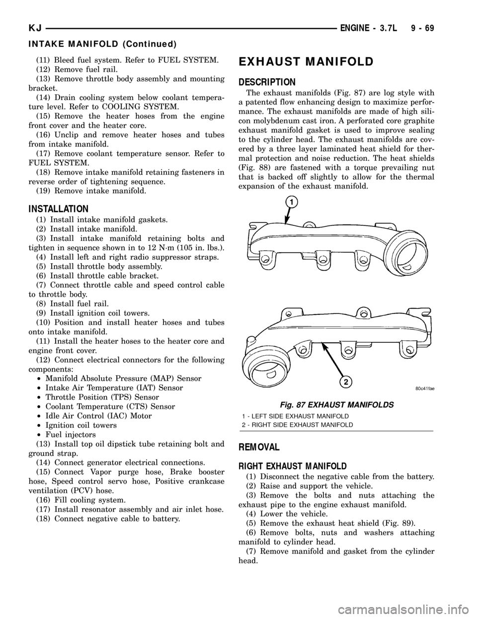
The exhaust manifolds (Fig. 87) are log style with
a patented flow enhancing design to maximize perfor-
mance. The exhaust manifolds are made of high sili-
con molybdenum cast iron. A perforated core graphite
exhaust manifold gasket is used to improve sealing
to the cylinder head. The exhaust manifolds are cov-
ered by a three layer laminated heat shield for ther-
mal protection and noise reduction. The heat shields
(Fig. 88) are fastened with a torque prevailing nut
that is backed off slightly to allow for the thermal
expansion of the exhaust manifold.
REMOVAL
RIGHT EXHAUST MANIFOLD
(1) Disconnect the negative cable from the battery.
(2) Raise and support the vehicle.
(3) Remove the bolts and nuts attaching the
exhaust pipe to the engine exhaust manifold.
(4) Lower the vehicle.
(5) Remove the exhaust heat shield (Fig. 89).
(6) Remove bolts, nuts and washers attaching
manifold to cylinder head.
(7) Remove manifold and gasket from the cylinder
head.
Fig. 87 EXHAUST MANIFOLDS
1 - LEFT SIDE EXHAUST MANIFOLD
2 - RIGHT SIDE EXHAUST MANIFOLD
KJENGINE - 3.7L 9 - 69
INTAKE MANIFOLD (Continued)
Page 1288 of 1803
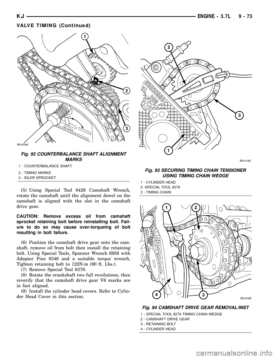
(5) Using Special Tool 8428 Camshaft Wrench,
rotate the camshaft until the alignment dowel on the
camshaft is aligned with the slot in the camshaft
drive gear.
CAUTION: Remove excess oil from camshaft
sprocket retaining bolt before reinstalling bolt. Fail-
ure to do so may cause over-torqueing of bolt
resulting in bolt failure.
(6) Position the camshaft drive gear onto the cam-
shaft, remove oil from bolt then install the retaining
bolt. Using Special Tools, Spanner Wrench 6958 with
Adapter Pins 8346 and a suitable torque wrench,
Tighten retaining bolt to 122N´m (90 ft. Lbs.).
(7) Remove Special Tool 8379.
(8) Rotate the crankshaft two full revolutions, then
reverify that the camshaft drive gear V6 marks are
in fact aligned.
(9) Install the cylinder head covers. Refer to Cylin-
der Head Cover in this section.
Fig. 92 COUNTERBALANCE SHAFT ALIGNMENT
MARKS
1 - COUNTERBALANCE SHAFT
2 - TIMING MARKS
3 - IDLER SPROCKET
Fig. 93 SECURING TIMING CHAIN TENSIONER
USING TIMING CHAIN WEDGE
1 - CYLINDER HEAD
2 -SPECIAL TOOL 8379
2 - TIMING CHAIN
Fig. 94 CAMSHAFT DRIVE GEAR REMOVAL/INST
1 - SPECIAL TOOL 8279 TIMING CHAIN WEDGE
2 - CAMSHAFT DRIVE GEAR
3 - RETAINING BOLT
4 - CYLINDER HEAD
KJENGINE - 3.7L 9 - 73
VALVE TIMING (Continued)