2002 JEEP LIBERTY fuel
[x] Cancel search: fuelPage 1364 of 1803

NOTE: Do not remove nut from T-Bolt. Only remove
nut far enough, so that the T end can be removed
from the clamp.
(6) Remove the T bolt end of the fastener, from the
clamp.
(7) Spread the clamp, and remove the catalytic
converter from the vehicle.
(8) Discard the clamp (Fig. 1).
NOTE: The catalytic converter to exhaust manifold
clamp is not reusable. Always use a new clamp
when reinstalling the catalytic converter.
INSPECTION
Look at the stainless steel body of the converter,
inspect for bulging or other distortion that could be a
result of overheating. If the converter has a heat
shield attached make sure it is not bent or loose.
If you suspect internal damage to the catalyst, tap-
ping the bottom of the catalyst with a rubber mallet
may indicate a damaged core.
INSTALLATION
(1) Position the catalytic converter onto the
exhaust pipe flange connection. Tighten the nuts to
28 N´m (250 in. lbs.) torque.(2) Install the muffler onto the catalytic converter
until the alignment tab is inserted into the align-
ment slot.
(3) Install the exhaust clamp at the muffler and
catalytic converter connection. Tighten the clamp
nuts to 47 N´m (35 ft. lbs.) torque.
(4) Connect oxygen sensor wiring.
(5) Lower the vehicle.
(6) Start the engine and inspect for exhaust leaks
and exhaust system contact with the body panels.
Adjust the alignment, if needed.
CROSS-OVER PIPE
REMOVAL
WARNING: IF TORCHES ARE USED WHEN WORK-
ING ON THE EXHAUST SYSTEM, DO NOT ALLOW
THE FLAME NEAR THE FUEL LINES.
WARNING: THE NORMAL OPERATING TEMPERA-
TURE OF THE EXHAUST SYSTEM IS VERY HIGH.
THEREFORE, NEVER WORK AROUND OR ATTEMPT
TO SERVICE ANY PART OF THE EXHAUST SYSTEM
UNTIL IT IS COOLED. SPECIAL CARE SHOULD BE
TAKEN WHEN WORKING NEAR THE CATALYTIC
CONVERTER. THE TEMPERATURE OF THE CON-
VERTER RISES TO A HIGH LEVEL AFTER A SHORT
PERIOD OF ENGINE OPERATION TIME.
(1) Raise and support the vehicle.
(2) Saturate the bolts and nuts with lubricant.
Allow 5 minutes for penetration.
(3) Remove the retaining fasteners holding cross-
over pipe to exhaust pipe.
(4) Remove the fasteners from the crossover pipe
to the catalytic converter connection.
(5) Remove the crossove pipe from the hanger
insulator (Fig. 2).
INSTALLATION
WARNING: IF TORCHES ARE USED WHEN WORK-
ING ON THE EXHAUST SYSTEM, DO NOT ALLOW
THE FLAME NEAR THE FUEL LINES.
Fig. 1 Catalyst Removal
1 - V-Clamp
2 - Catalytic Converter
3 - Flange
4 - Crossover Pipe
5 - T-Bolt
KJEXHAUST SYSTEM 11 - 3
CATALYTIC CONVERTER (Continued)
Page 1366 of 1803

REMOVAL
All original equipment exhaust systems are manu-
factured with the exhaust tailpipe welded to the muf-
fler. Service replacement mufflers and exhaust
tailpipes are either clamped together or welded
together.
WARNING: IF TORCHES ARE USED WHEN WORK-
ING ON THE EXHAUST SYSTEM, DO NOT ALLOW
THE FLAME NEAR THE FUEL LINE.
CAUTION: When servicing exhaust system compo-
nents, disconnect the oxygen sensor connector.
Allowing the exhaust system to hang by the oxygen
sensor harness will damage the wiring and/or sen-
sor.
(1) Raise and support the vehicle.
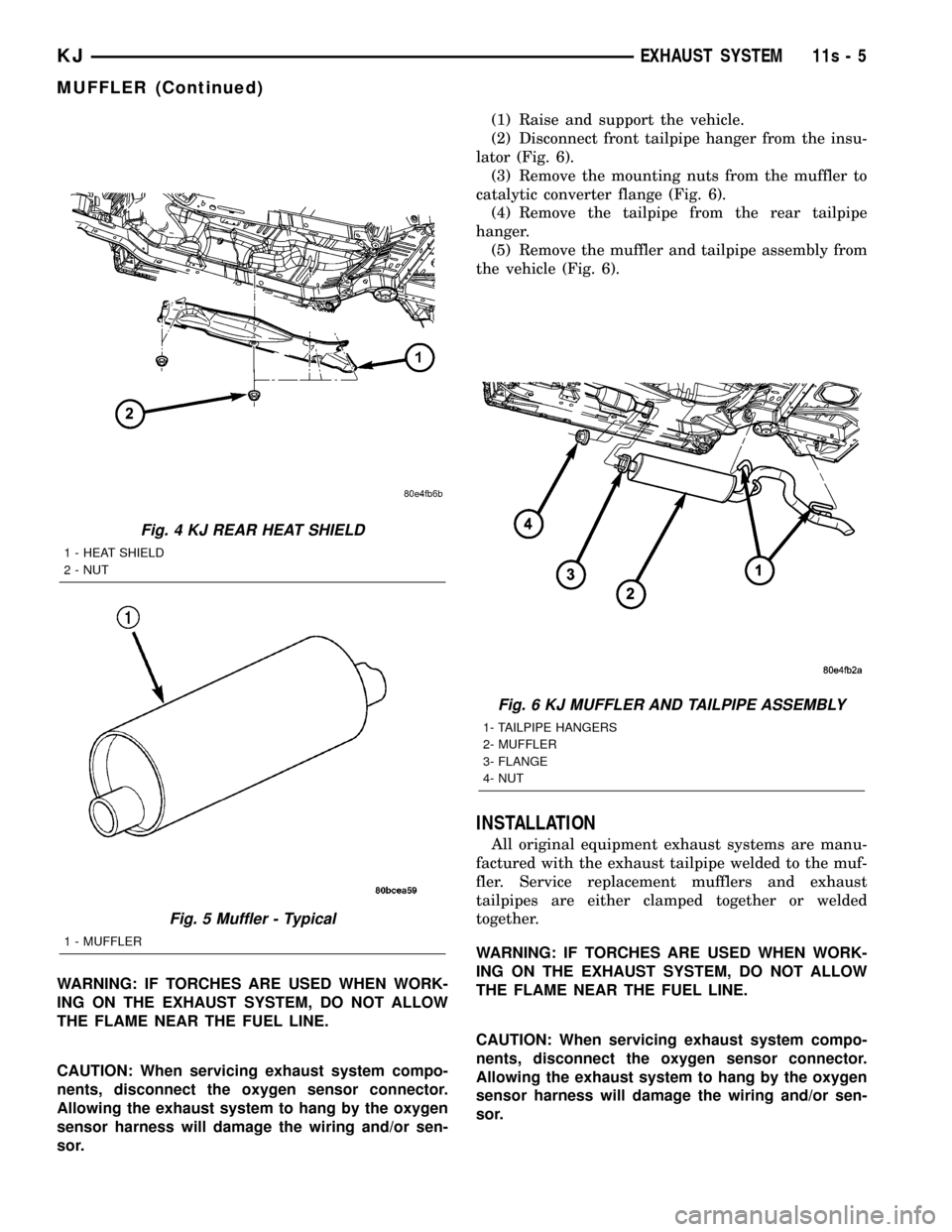
(2) Disconnect front tailpipe hanger from the insu-
lator (Fig. 5).
(3) Remove the mounting nuts from the muffler to
catalytic converter flange (Fig. 5).
(4) Remove the tailpipe from the rear tailpipe
hanger (Fig. 5).
(5) Remove the muffler and tailpipe assembly from
the vehicle.
INSTALLATION
All original equipment exhaust systems are manu-
factured with the exhaust tailpipe welded to the muf-fler. Service replacement mufflers and exhaust
tailpipes are either clamped together or welded
together.
WARNING: IF TORCHES ARE USED WHEN WORK-
ING ON THE EXHAUST SYSTEM, DO NOT ALLOW
THE FLAME NEAR THE FUEL LINE.
CAUTION: When servicing exhaust system compo-
nents, disconnect the oxygen sensor connector.
Allowing the exhaust system to hang by the oxygen
sensor harness will damage the wiring and/or sen-
sor.
(1) Position muffler and tailpipe assembly into
vehicle.
(2) Install clamp retaining tailpipe to the rear
tailpipe hanger (Fig. 5).DO NOTtighten clamp at
this time.
(3) Install mounting nuts onto the muffler to cata-
lytic converter flange studs (Fig. 5).DO NOTtighten
nuts at this time.
(4) Make sure the exhaust system is in proper
alignment. There should be at least 25mm (1 inch)
clearance between the exhaust components and any
surrounding components.
(5) Tighten muffler to catalytic converter flange
mounting nuts to 28.5 N´m (21 ft. lbs.).
(6) Tighten tailpipe clamp to 48 N´m (35 ft. lbs.).
KJEXHAUST SYSTEM 11 - 5
MUFFLER (Continued)
Page 1369 of 1803

DIAGNOSIS AND TESTING - EXHAUST SYSTEM
EXHAUST SYSTEM DIAGNOSIS CHART
CONDITION POSSIBLE CAUSE CORRECTION
EXCESSIVE EXHAUST NOISE OR
LEAKING EXHAUST GASES1. Leaks at pipe joints. 1. Tighten clamps/bolts to specified
torque at leaking joints.
2. Rusted or blown out muffler. 2. Replace muffler. Inspect exhaust
system.
3. Broken or rusted out exhaust
pipe.3. Replace exhaust pipe.
4. Exhaust pipe leaking at manifold
flange.4. Tighten/replace flange attaching
nuts/bolts.
5. Exhaust manifold cracked or
broken.5. Replace exhaust manifold.
6. Leak between exhaust manifold
and cylinder head.6. Tighten exhaust manifold to
cylinder head bolts.
7. Catalytic converter rusted or
blown out.7. Replace catalytic converter assy.
8. Restriction in exhaust system. 8. Remove restriction, if possible.
Replace restricted part if necessary.
CAUTION:
When servicing and replacing exhaust system components, disconnect the oxygen sensor connector(s). Allowing
the exhaust to hang by the oxygen sensor wires will damage the harness and/or sensor.
CATALYTIC CONVERTER
DESCRIPTION - CATALYTIC CONVERTER
WARNING: THE NORMAL OPERATING TEMPERA-
TURE OF THE EXHAUST SYSTEM IS VERY HIGH.
THEREFORE, NEVER WORK AROUND OR ATTEMPT
TO SERVICE ANY PART OF THE EXHAUST SYSTEM
UNTIL IT IS COOLED. SPECIAL CARE SHOULD BE
TAKEN WHEN WORKING NEAR THE CATALYTIC
CONVERTER. THE TEMPERATURE OF THE CON-
VERTER RISES TO A HIGH LEVEL AFTER A SHORT
PERIOD OF ENGINE OPERATION TIME.
CAUTION: DO NOT remove spark plug wires from
plugs or by any other means short out cylinders.
Failure of the catalytic converter can occur due to a
temperature increase caused by unburned fuel
passing through the converter.
The stainless steel catalytic converter body is
designed to last the life of the vehicle. Excessive heat
can result in bulging or other distortion, but exces-
sive heat will not be the fault of the converter. If
unburned fuel enters the converter, overheating may
occur. If a converter is heat-damaged, correct thecause of the damage at the same time the converter
is replaced. Also, inspect all other components of the
exhaust system for heat damage.
Unleaded gasoline must be used to avoid con-
taminating the catalyst core.
50 State emission vehicles incorporate two mini
catalytic converters located after the exhaust mani-
folds and before the inline catalytic converter.
REMOVAL
WARNING: IF TORCHES ARE USED WHEN WORK-
ING ON THE EXHAUST SYSTEM, DO NOT ALLOW
THE FLAME NEAR THE FUEL LINES.
(1) Raise and support the vehicle.
(2) Saturate the bolts and nuts with heat valve
lubricant. Allow 5 minutes for penetration.
(3) Remove the bolts from the crossover pipe to the
catalytic converter connection.
(4) Disconnect oxygen sensor wiring.
(5) Loosen and remove the nuts from the clamp
that hold the catalytic converter to the exhaust pipe
flange connection.
11s - 2 EXHAUST SYSTEMKJ
EXHAUST SYSTEM (Continued)
Page 1371 of 1803

CROSS-OVER PIPE
REMOVAL
WARNING: IF TORCHES ARE USED WHEN WORK-
ING ON THE EXHAUST SYSTEM, DO NOT ALLOW
THE FLAME NEAR THE FUEL LINES.
WARNING: THE NORMAL OPERATING TEMPERA-
TURE OF THE EXHAUST SYSTEM IS VERY HIGH.
THEREFORE, NEVER WORK AROUND OR ATTEMPT
TO SERVICE ANY PART OF THE EXHAUST SYSTEM
UNTIL IT IS COOLED. SPECIAL CARE SHOULD BE
TAKEN WHEN WORKING NEAR THE CATALYTIC
CONVERTER. THE TEMPERATURE OF THE CON-
VERTER RISES TO A HIGH LEVEL AFTER A SHORT
PERIOD OF ENGINE OPERATION TIME.
(1) Raise and support the vehicle.
(2) Saturate the bolts and nuts with lubricant.
Allow 5 minutes for penetration.
(3) Remove the retaining fasteners holding cross-
over pipe to exhaust pipe.
(4) Remove the fasteners from the crossover pipe
to the catalytic converter connection.
(5) Remove the crossove pipe from the hanger
insulator (Fig. 3).
INSTALLATION
WARNING: IF TORCHES ARE USED WHEN WORK-
ING ON THE EXHAUST SYSTEM, DO NOT ALLOW
THE FLAME NEAR THE FUEL LINES.
WARNING: THE NORMAL OPERATING TEMPERA-
TURE OF THE EXHAUST SYSTEM IS VERY HIGH.
THEREFORE, NEVER WORK AROUND OR ATTEMPT
TO SERVICE ANY PART OF THE EXHAUST SYSTEM
UNTIL IT IS COOLED. SPECIAL CARE SHOULD BE
TAKEN WHEN WORKING NEAR THE CATALYTIC
CONVERTER. THE TEMPERATURE OF THE CON-
VERTER RISES TO A HIGH LEVEL AFTER A SHORT
PERIOD OF ENGINE OPERATION TIME.
(1) Install the crossove pipe into the hanger insu-
lator.
(2) Install and torque the fasteners in the cross-
over pipe to the left and right catalytic converter con-
nection.
(3) Install and torque the retaining fasteners hold-
ing the crossover pipe to exhaust pipe.
(4) Lower vehicle..
(5) Start engine and check for leaks.
HEAT SHIELDS
DESCRIPTION
Heat shields (Fig. 4) are needed to protect both the
vehicle and the environment from the high tempera-
tures developed by the catalytic converter. The cata-
lytic converter releases additional heat into the
exhaust system. Under severe operating conditions,
the temperature increases in the area of the con-
verter. Such conditions can exist when the engine
misfires or otherwise does not operate at peak effi-
ciency.
MUFFLER
DESCRIPTION
The 2.4L and 3.7L engine uses a galvanized steel
muffler (Fig. 5) to control exhaust noise levels and
exhaust back pressure.
REMOVAL
All original equipment exhaust systems are manu-
factured with the exhaust tailpipe welded to the muf-
fler. Service replacement mufflers and exhaust
tailpipes are either clamped together or welded
together.Fig. 3 Crossover Pipe
1 - Crossover-toCatalytic Converter flange
2 - Crossover Pipe
3 - Crossover Pipe to Tail Pipe Flange
4 - Hanger Bracket
11s - 4 EXHAUST SYSTEMKJ
Page 1372 of 1803

WARNING: IF TORCHES ARE USED WHEN WORK-
ING ON THE EXHAUST SYSTEM, DO NOT ALLOW
THE FLAME NEAR THE FUEL LINE.
CAUTION: When servicing exhaust system compo-
nents, disconnect the oxygen sensor connector.
Allowing the exhaust system to hang by the oxygen
sensor harness will damage the wiring and/or sen-
sor.(1) Raise and support the vehicle.
(2) Disconnect front tailpipe hanger from the insu-
lator (Fig. 6).
(3) Remove the mounting nuts from the muffler to
catalytic converter flange (Fig. 6).
(4) Remove the tailpipe from the rear tailpipe
hanger.
(5) Remove the muffler and tailpipe assembly from
the vehicle (Fig. 6).
INSTALLATION
All original equipment exhaust systems are manu-
factured with the exhaust tailpipe welded to the muf-
fler. Service replacement mufflers and exhaust
tailpipes are either clamped together or welded
together.
WARNING: IF TORCHES ARE USED WHEN WORK-
ING ON THE EXHAUST SYSTEM, DO NOT ALLOW
THE FLAME NEAR THE FUEL LINE.
CAUTION: When servicing exhaust system compo-
nents, disconnect the oxygen sensor connector.
Allowing the exhaust system to hang by the oxygen
sensor harness will damage the wiring and/or sen-
sor.
Fig. 4 KJ REAR HEAT SHIELD
1 - HEAT SHIELD
2 - NUT
Fig. 5 Muffler - Typical
1 - MUFFLER
Fig. 6 KJ MUFFLER AND TAILPIPE ASSEMBLY
1- TAILPIPE HANGERS
2- MUFFLER
3- FLANGE
4- NUT
KJEXHAUST SYSTEM 11s - 5
MUFFLER (Continued)
Page 1374 of 1803

FRAMES & BUMPERS
TABLE OF CONTENTS
page page
FRONT FASCIA
REMOVAL.............................1
INSTALLATION..........................2
REAR FASCIA
REMOVAL.............................2
INSTALLATION..........................2
REAR FASCIA SUPPORT
REMOVAL.............................3
INSTALLATION..........................3
FRAME
SPECIFICATIONS
SPECIFICATIONS - FRAME DIMENSIONS . . . 3
SPECIFICATIONS - TORQUE.............6
FRONT SKID PLATE
REMOVAL.............................6
INSTALLATION..........................6
ENGINE CRADLE CROSSMEMBER
REMOVAL.............................6
INSTALLATION..........................6TRANSFER CASE SKID PLATE
REMOVAL.............................7
INSTALLATION..........................7
REAR CROSSMEMBER
REMOVAL.............................7
INSTALLATION..........................7
FRONT TOW HOOK
REMOVAL.............................8
INSTALLATION..........................8
REAR TOW HOOK
REMOVAL.............................8
INSTALLATION..........................8
TRAILER HITCH
REMOVAL.............................9
INSTALLATION..........................9
FUEL TANK SKID PLATE
REMOVAL.............................9
INSTALLATION..........................9
FRONT FASCIA
REMOVAL
(1) Remove the grille. (Refer to 23 - BODY/EXTE-
RIOR/GRILLE - REMOVAL)
(2) Raise and support vehicle.
(3) Remove the front wheel opening flare moldings.
(Refer to 23 - BODY/EXTERIOR/FRONT WHEEL
OPENING FLARE MOLDINGS - REMOVAL)
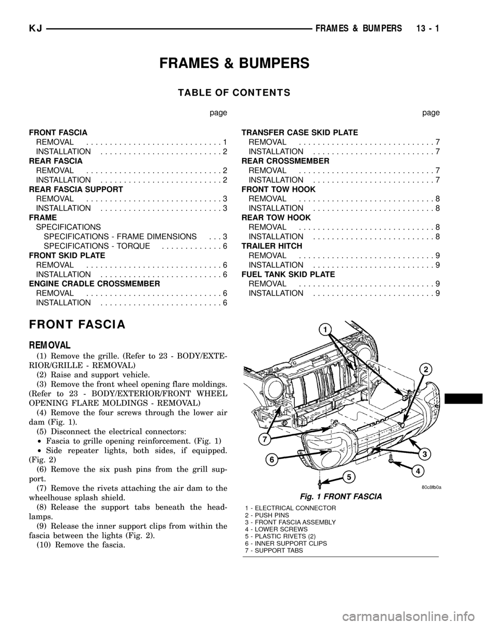
(4) Remove the four screws through the lower air
dam (Fig. 1).
(5) Disconnect the electrical connectors:
²Fascia to grille opening reinforcement. (Fig. 1)
²Side repeater lights, both sides, if equipped.
(Fig. 2)
(6) Remove the six push pins from the grill sup-
port.
(7) Remove the rivets attaching the air dam to the
wheelhouse splash shield.
(8) Release the support tabs beneath the head-
lamps.
(9) Release the inner support clips from within the
fascia between the lights (Fig. 2).
(10) Remove the fascia.
Fig. 1 FRONT FASCIA
1 - ELECTRICAL CONNECTOR
2 - PUSH PINS
3 - FRONT FASCIA ASSEMBLY
4 - LOWER SCREWS
5 - PLASTIC RIVETS (2)
6 - INNER SUPPORT CLIPS
7 - SUPPORT TABS
KJFRAMES & BUMPERS 13 - 1
Page 1379 of 1803

SPECIFICATIONS - TORQUE
DESCRIPTION N´m Ft. Lbs. In. Lbs.
ENGINE CRADLE CROSSMEMBER INNER RAIL BOLTS 47 35 Ð
ENGINE CRADLE CROSSMEMBER MOUNTING BOLTS 122 90 Ð
ENGINE MOUNT THROUGH BOLTS/NUTS 88 65 Ð
FRONT SKID PLATE BOLTS 61 45 Ð
FRONT TOW HOOK NUTS/BOLT 61 45 Ð
FUEL TANK SKID PLATE 88 65 Ð
REAR CROSSMEMBER BOLTS 47 35 Ð
REAR TOW HOOK BOLTS 88 65 Ð
TRAILER HITCH BOLTS 88 65 Ð
TRANSFER CASE SKID PLATE BOLTS 34 25 Ð
TRANSMISSION MOUNT THROUGH BOLT/NUT 88 65 Ð
FRONT SKID PLATE
REMOVAL
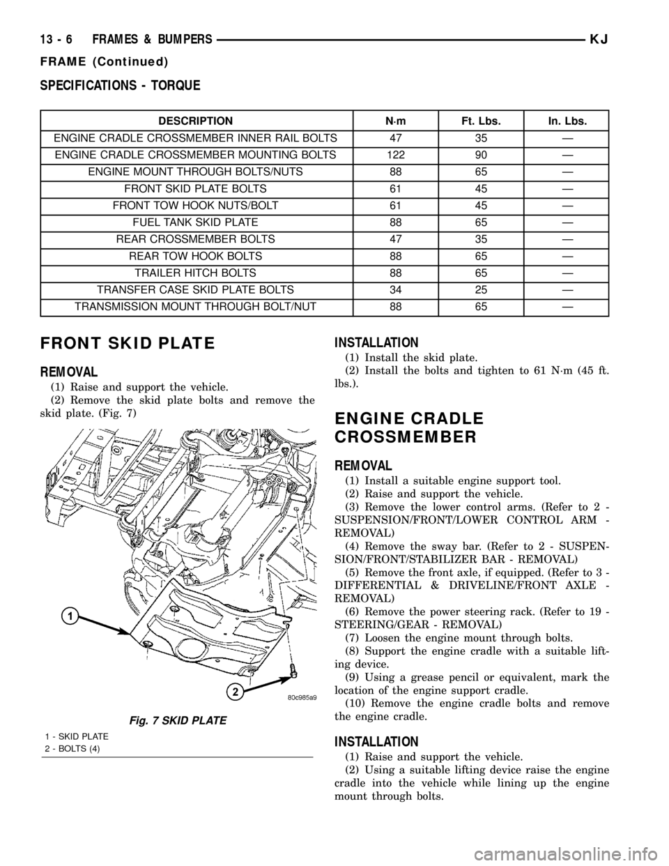
(1) Raise and support the vehicle.
(2) Remove the skid plate bolts and remove the
skid plate. (Fig. 7)
INSTALLATION
(1) Install the skid plate.
(2) Install the bolts and tighten to 61 N´m (45 ft.
lbs.).
ENGINE CRADLE
CROSSMEMBER
REMOVAL
(1) Install a suitable engine support tool.
(2) Raise and support the vehicle.
(3) Remove the lower control arms. (Refer to 2 -
SUSPENSION/FRONT/LOWER CONTROL ARM -
REMOVAL)
(4) Remove the sway bar. (Refer to 2 - SUSPEN-
SION/FRONT/STABILIZER BAR - REMOVAL)
(5) Remove the front axle, if equipped. (Refer to 3 -
DIFFERENTIAL & DRIVELINE/FRONT AXLE -
REMOVAL)
(6) Remove the power steering rack. (Refer to 19 -
STEERING/GEAR - REMOVAL)
(7) Loosen the engine mount through bolts.
(8) Support the engine cradle with a suitable lift-
ing device.
(9) Using a grease pencil or equivalent, mark the
location of the engine support cradle.
(10) Remove the engine cradle bolts and remove
the engine cradle.
INSTALLATION
(1) Raise and support the vehicle.
(2) Using a suitable lifting device raise the engine
cradle into the vehicle while lining up the engine
mount through bolts.
Fig. 7 SKID PLATE
1 - SKID PLATE
2 - BOLTS (4)
13 - 6 FRAMES & BUMPERSKJ
FRAME (Continued)
Page 1382 of 1803

TRAILER HITCH
REMOVAL
(1) Remove the tow hooks, if equipped. (Refer to 13
- FRAME & BUMPERS/FRAME/REAR TOW HOOK
- REMOVAL)
(2) Disconnect trailer electrical connector.
(3) Support the hitch with a suitable lifting device.
(4) Remove the bolts and remove the trailer hitch.
(Fig. 12)
INSTALLATION
(1) Support the hitch with a suitable lifting device
and install the hitch.
(2) Install the bolts and tighten to 88 N´m (65 ft.
lbs.)
(3) Connect the electrical connector.
FUEL TANK SKID PLATE
REMOVAL
(1) Raise and support the vehicle.
(2) Support the skid plate with a suitable lifting
device.
(3) Remove the trailer hitch, if equipped. (Refer to
13 - FRAME & BUMPERS/FRAME/TRAILER
HITCH - REMOVAL)
(4) Remove the tow hooks, if not previously
removed. (Refer to 13 - FRAME & BUMPERS/
FRAME/REAR TOW HOOK - REMOVAL)
(5) Remove the bolts and remove the fuel tank
skid plate.
INSTALLATION
(1) Install the skid plate and support with a suit-
able lifting device.(2) Install the trailer hitch, if equipped. (Refer to
13 - FRAME & BUMPERS/FRAME/TRAILER
HITCH - INSTALLATION)
(3) Install the tow hooks, if equipped. (Refer to 13
- FRAME & BUMPERS/FRAME/REAR TOW HOOK
- INSTALLATION)
(4) Install the bolts and tighten to 88 N´m (65 ft.
lbs.).
Fig. 12 TRAILER HITCH
1 - BOLTS
2 - TRAILER LIGHTS ELECTRICAL CONNECTOR
3 - TRAILER HITCH
KJFRAMES & BUMPERS 13 - 9