2002 JEEP LIBERTY rear door
[x] Cancel search: rear doorPage 1610 of 1803
SIDE VIEW MIRROR
REMOVAL
(1) Remove the trim panel. (Refer to 23 - BODY/
DOOR - FRONT/TRIM PANEL - REMOVAL)
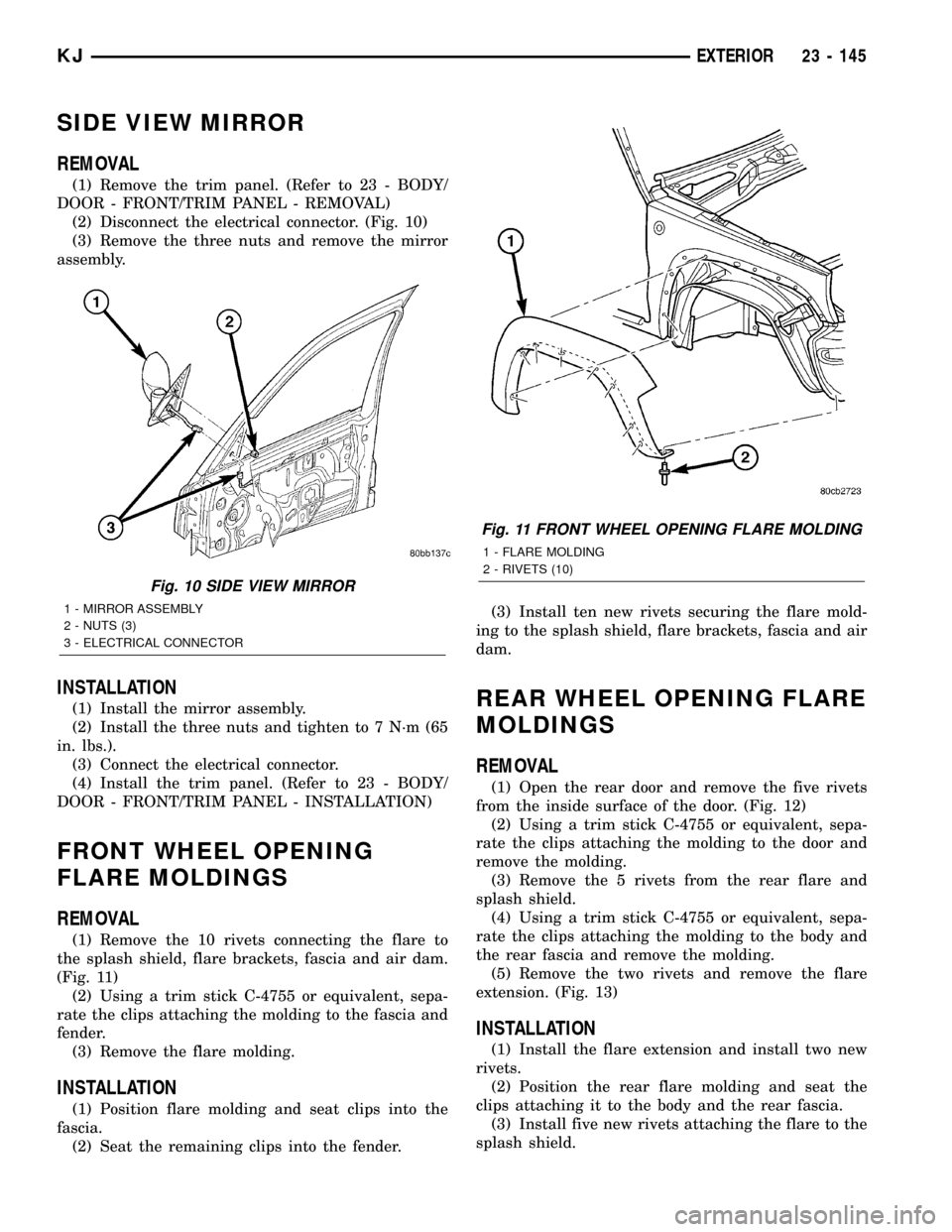
(2) Disconnect the electrical connector. (Fig. 10)
(3) Remove the three nuts and remove the mirror
assembly.
INSTALLATION
(1) Install the mirror assembly.
(2) Install the three nuts and tighten to 7 N´m (65
in. lbs.).
(3) Connect the electrical connector.
(4) Install the trim panel. (Refer to 23 - BODY/
DOOR - FRONT/TRIM PANEL - INSTALLATION)
FRONT WHEEL OPENING
FLARE MOLDINGS
REMOVAL
(1) Remove the 10 rivets connecting the flare to
the splash shield, flare brackets, fascia and air dam.
(Fig. 11)
(2) Using a trim stick C-4755 or equivalent, sepa-
rate the clips attaching the molding to the fascia and
fender.
(3) Remove the flare molding.
INSTALLATION
(1) Position flare molding and seat clips into the
fascia.
(2) Seat the remaining clips into the fender.(3) Install ten new rivets securing the flare mold-
ing to the splash shield, flare brackets, fascia and air
dam.
REAR WHEEL OPENING FLARE
MOLDINGS
REMOVAL
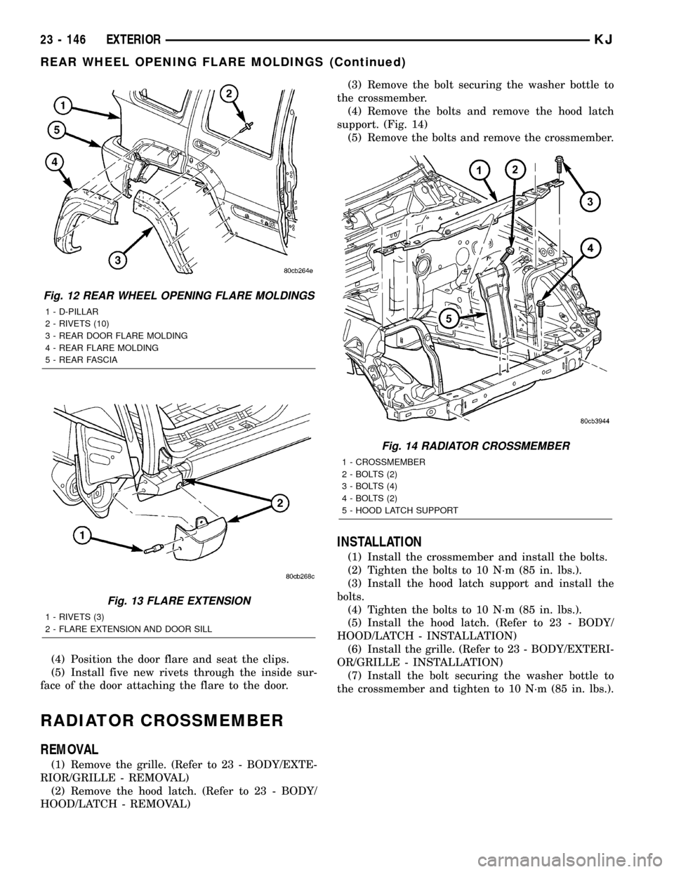
(1) Open the rear door and remove the five rivets
from the inside surface of the door. (Fig. 12)
(2) Using a trim stick C-4755 or equivalent, sepa-
rate the clips attaching the molding to the door and
remove the molding.
(3) Remove the 5 rivets from the rear flare and
splash shield.
(4) Using a trim stick C-4755 or equivalent, sepa-
rate the clips attaching the molding to the body and
the rear fascia and remove the molding.
(5) Remove the two rivets and remove the flare
extension. (Fig. 13)
INSTALLATION
(1) Install the flare extension and install two new
rivets.
(2) Position the rear flare molding and seat the
clips attaching it to the body and the rear fascia.
(3) Install five new rivets attaching the flare to the
splash shield.
Fig. 10 SIDE VIEW MIRROR
1 - MIRROR ASSEMBLY
2 - NUTS (3)
3 - ELECTRICAL CONNECTOR
Fig. 11 FRONT WHEEL OPENING FLARE MOLDING
1 - FLARE MOLDING
2 - RIVETS (10)
KJEXTERIOR 23 - 145
Page 1611 of 1803
(4) Position the door flare and seat the clips.
(5) Install five new rivets through the inside sur-
face of the door attaching the flare to the door.
RADIATOR CROSSMEMBER
REMOVAL
(1) Remove the grille. (Refer to 23 - BODY/EXTE-
RIOR/GRILLE - REMOVAL)
(2) Remove the hood latch. (Refer to 23 - BODY/
HOOD/LATCH - REMOVAL)(3) Remove the bolt securing the washer bottle to
the crossmember.
(4) Remove the bolts and remove the hood latch
support. (Fig. 14)
(5) Remove the bolts and remove the crossmember.
INSTALLATION
(1) Install the crossmember and install the bolts.
(2) Tighten the bolts to 10 N´m (85 in. lbs.).
(3) Install the hood latch support and install the
bolts.
(4) Tighten the bolts to 10 N´m (85 in. lbs.).
(5) Install the hood latch. (Refer to 23 - BODY/
HOOD/LATCH - INSTALLATION)
(6) Install the grille. (Refer to 23 - BODY/EXTERI-
OR/GRILLE - INSTALLATION)
(7) Install the bolt securing the washer bottle to
the crossmember and tighten to 10 N´m (85 in. lbs.).
Fig. 12 REAR WHEEL OPENING FLARE MOLDINGS
1 - D-PILLAR
2 - RIVETS (10)
3 - REAR DOOR FLARE MOLDING
4 - REAR FLARE MOLDING
5 - REAR FASCIA
Fig. 13 FLARE EXTENSION
1 - RIVETS (3)
2 - FLARE EXTENSION AND DOOR SILL
Fig. 14 RADIATOR CROSSMEMBER
1 - CROSSMEMBER
2 - BOLTS (2)
3 - BOLTS (4)
4 - BOLTS (2)
5 - HOOD LATCH SUPPORT
23 - 146 EXTERIORKJ
REAR WHEEL OPENING FLARE MOLDINGS (Continued)
Page 1621 of 1803
INTERIOR
TABLE OF CONTENTS
page page
4WD FLOOR SHIFT BOOT
REMOVAL............................156
INSTALLATION........................156
A-PILLAR TRIM AND GRAB HANDLE
REMOVAL............................156
INSTALLATION........................156
COWL TRIM COVER
REMOVAL............................157
INSTALLATION........................157
DOOR SILL SCUFF PLATE
REMOVAL............................157
INSTALLATION........................157
ASSIST HANDLE
REMOVAL............................157
INSTALLATION........................157
B-PILLAR LOWER TRIM
REMOVAL............................157
INSTALLATION........................157
B-PILLAR UPPER TRIM
REMOVAL............................157
INSTALLATION........................158
CARPETS AND FLOOR MATS
REMOVAL............................158
INSTALLATION........................158
SHIFT BEZEL
REMOVAL............................158
INSTALLATION........................158FLOOR CONSOLE
REMOVAL............................158
INSTALLATION........................158
FLOOR CONSOLE LID LATCH
REMOVAL............................158
INSTALLATION........................158
HEADLINER
REMOVAL............................159
INSTALLATION........................159
QUARTER TRIM PANEL
REMOVAL............................159
INSTALLATION........................159
REAR DOOR SCUFF PLATE
REMOVAL............................160
INSTALLATION........................160
SUN VISOR
REMOVAL............................160
INSTALLATION........................160
SUN VISOR SUPPORT
REMOVAL............................160
INSTALLATION........................160
REAR VIEW MIRROR
REMOVAL............................161
INSTALLATION
INSTALLATION......................161
INSTALLATION - REARVIEW MIRROR
SUPPORT BRACKET..................161
4WD FLOOR SHIFT BOOT
REMOVAL
(1) Remove the shift lever and remove the boot
from the lever. (Refer to 21 - TRANSMISSION/
TRANSAXLE/TRANSFER CASE/SHIFT LEVER -
REMOVAL)
INSTALLATION
(1) Install the shift boot onto the shift lever and
install the lever. (Refer to 21 - TRANSMISSION/
TRANSAXLE/TRANSFER CASE/SHIFT LEVER -
INSTALLATION)
A-PILLAR TRIM AND GRAB
HANDLE
REMOVAL
(1) Using a small pry tool or equivalent, remove
the grab handle trim plugs.
(2) Remove the two grab handle screws.
(3) Remove the grab handle and a-pillar trim from
the a-pillar.
INSTALLATION
(1) Snap a-pillar trim and grab handle into the
a-pillar.
(2) Install the two screws and install the grab han-
dle trim plugs.
23 - 156 INTERIORKJ
Page 1625 of 1803
(3) Install the belt access panel.
(4) Install the seat belt anchor and pivot. (Refer to
8 - ELECTRICAL/RESTRAINTS/SEAT BELT &
RETRACTOR - INSTALLATION)
(5) Install the hook pin type connector.
(6) Position the rear sill plate and seat the retain-
ing clips.
(7) Position the rear header trim and seat the
retaining clips.
REAR DOOR SCUFF PLATE
REMOVAL
(1) Using a trim stick C-4755 or equivalent,
release the retaining clips and remove the scuff
plate.
INSTALLATION
(1) Position the scuff plate and seat the retaining
clips.
SUN VISOR
REMOVAL
(1) Remove the screws at the visor pivot.
(2) Disconnect the electrical connector and remove
the visor.
INSTALLATION
(1) Connect the electrical connector and install the
visor.
(2) Install the screws at the visor pivots.
SUN VISOR SUPPORT
REMOVAL
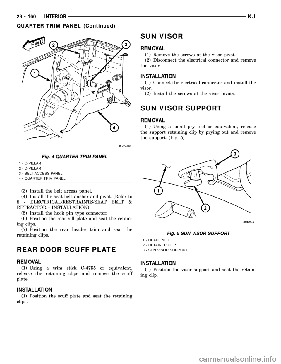
(1) Using a small pry tool or equivalent, release
the support retaining clip by prying out and remove
the support. (Fig. 5)
INSTALLATION
(1) Position the visor support and seat the retain-
ing clip.
Fig. 4 QUARTER TRIM PANEL
1 - C-PILLAR
2 - D-PILLAR
3 - BELT ACCESS PANEL
4 - QUARTER TRIM PANEL
Fig. 5 SUN VISOR SUPPORT
1 - HEADLINER
2 - RETAINER CLIP
3 - SUN VISOR SUPPORT
23 - 160 INTERIORKJ
QUARTER TRIM PANEL (Continued)
Page 1633 of 1803
INSTALLATION
(1) Install the seat riser and install the bolts.
(2) Tighten the bolts to 28 N´m (21 ft. lbs.).
(3) Install a new release handle rivet.
(4) Install the seat. (Refer to 23 - BODY/SEATS/
SEAT - FRONT - INSTALLATION)
SEAT TRACK
REMOVAL
(1) Remove the seat back. (Refer to 23 - BODY/
SEATS/SEAT BACK - FRONT - REMOVAL)
(2) Remove the outer riser. (Refer to 23 - BODY/
SEATS/SEAT RISER - REMOVAL)
(3) Remove the front outer bolts and remove the
tracks.
INSTALLATION
(1) Install the seat track onto the seat cushion and
install the front outer bolts.
(2) Tighten the bolts to 28 N´m (21 ft. lbs.).
(3) Install the seat riser. (Refer to 23 - BODY/
SEATS/SEAT RISER - INSTALLATION)
(4) Install the seat back. (Refer to 23 - BODY/
SEATS/SEAT BACK - FRONT - INSTALLATION)
SEAT - REAR
REMOVAL
(1) Remove the outer seat belt anchors. (Refer to 8
- ELECTRICAL/RESTRAINTS/SEAT BELT &
RETRACTOR - REMOVAL)
(2) Remove the inner seat belt buckles. (Refer to 8
- ELECTRICAL/RESTRAINTS/SEAT BELT BUCKLE
- REMOVAL)
(3) Remove the center seat belt anchor. (Refer to 8
- ELECTRICAL/RESTRAINTS/SEAT BELT &
RETRACTOR - REMOVAL)
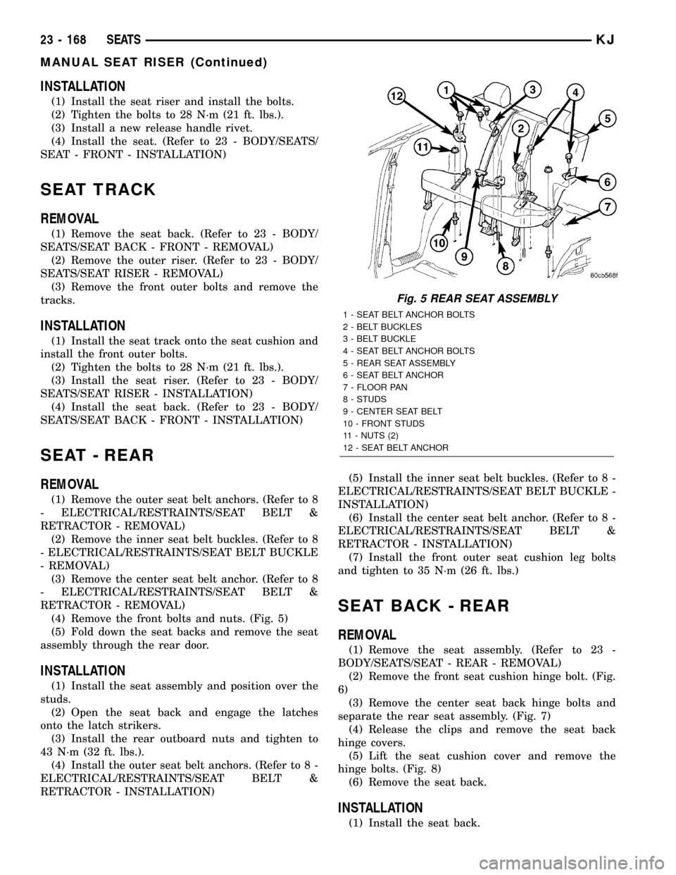
(4) Remove the front bolts and nuts. (Fig. 5)
(5) Fold down the seat backs and remove the seat
assembly through the rear door.
INSTALLATION
(1) Install the seat assembly and position over the
studs.
(2) Open the seat back and engage the latches
onto the latch strikers.
(3) Install the rear outboard nuts and tighten to
43 N´m (32 ft. lbs.).
(4) Install the outer seat belt anchors. (Refer to 8 -
ELECTRICAL/RESTRAINTS/SEAT BELT &
RETRACTOR - INSTALLATION)(5) Install the inner seat belt buckles. (Refer to 8 -
ELECTRICAL/RESTRAINTS/SEAT BELT BUCKLE -
INSTALLATION)
(6) Install the center seat belt anchor. (Refer to 8 -
ELECTRICAL/RESTRAINTS/SEAT BELT &
RETRACTOR - INSTALLATION)
(7) Install the front outer seat cushion leg bolts
and tighten to 35 N´m (26 ft. lbs.)
SEAT BACK - REAR
REMOVAL
(1) Remove the seat assembly. (Refer to 23 -
BODY/SEATS/SEAT - REAR - REMOVAL)
(2) Remove the front seat cushion hinge bolt. (Fig.
6)
(3) Remove the center seat back hinge bolts and
separate the rear seat assembly. (Fig. 7)
(4) Release the clips and remove the seat back
hinge covers.
(5) Lift the seat cushion cover and remove the
hinge bolts. (Fig. 8)
(6) Remove the seat back.
INSTALLATION
(1) Install the seat back.
Fig. 5 REAR SEAT ASSEMBLY
1 - SEAT BELT ANCHOR BOLTS
2 - BELT BUCKLES
3 - BELT BUCKLE
4 - SEAT BELT ANCHOR BOLTS
5 - REAR SEAT ASSEMBLY
6 - SEAT BELT ANCHOR
7 - FLOOR PAN
8 - STUDS
9 - CENTER SEAT BELT
10 - FRONT STUDS
11 - NUTS (2)
12 - SEAT BELT ANCHOR
23 - 168 SEATSKJ
MANUAL SEAT RISER (Continued)
Page 1637 of 1803
STATIONARY GLASS
TABLE OF CONTENTS
page page
DOOR GLASS
REMOVAL............................172
INSTALLATION........................172
QUARTER WINDOW
REMOVAL............................172
INSTALLATION........................172WINDSHIELD
WARNING
WINDSHIELD SAFETY PRECAUTIONS....173
REMOVAL............................173
INSTALLATION........................173
DOOR GLASS
REMOVAL
(1) Remove the rear door glass run channel. (Refer
to 23 - BODY/DOORS - REAR/GLASS RUN CHAN-
NEL - REMOVAL)
INSTALLATION
(1) Install the rear door glass run channel. (Refer
to 23 - BODY/DOORS - REAR/GLASS RUN CHAN-
NEL - INSTALLATION)
QUARTER WINDOW
REMOVAL
(1) Remove the headliner as necessary to gain
access to the glass seal from the inside. (Refer to 23 -
BODY/INTERIOR/HEADLINER - REMOVAL)
(2) Cut urethane bonding from around quarter
window glass using a suitable sharp cold knife. A
pneumatic cutting device can be used if available.
(3) Separate glass from vehicle.
INSTALLATION
CAUTION: Open a window before installing glass.
This will avoid pressurizing the passenger compart-
ment. If a door or swing gate flip-up glass is
slammed before urethane is cured, water leaks can
result.
The window opening fence should be cleaned of old
urethane bonding material.
(1) Install the headliner as necessary. (Refer to 23
- BODY/INTERIOR/HEADLINER - INSTALLATION)
(2) Clean inside of glass with Mopar Glass Cleaner
and lint-free cloth.
(3) Apply PVC (vinyl) primer 25 mm (1 in.) wide
around edge of glass. Wipe with clean/dry lint-free
cloth.
(4) Apply fence primer around edge of fence. Allow
at least eighteen minutes drying time.
(5) Apply a 10 mm (0.4 in.) bead of urethane
around window vinyl border location.
(6)
Position glass into window opening and lock clips
into place.
23 - 172 STATIONARY GLASSKJ
Page 1638 of 1803
WINDSHIELD
WARNING
WINDSHIELD SAFETY PRECAUTIONS
WARNING: DO NOT OPERATE THE VEHICLE
WITHIN 24 HOURS OF WINDSHIELD INSTALLATION.
IT TAKES AT LEAST 24 HOURS FOR URETHANE
ADHESIVE TO CURE. IF IT IS NOT CURED, THE
WINDSHIELD MAY NOT PERFORM PROPERLY IN
AN ACCIDENT.
²URETHANE ADHESIVES ARE APPLIED AS A
SYSTEM. USE GLASS CLEANER, GLASS PREP
SOLVENT, GLASS PRIMER, PVC (VINYL) PRIMER
AND PINCH WELD (FENCE) PRIMER PROVIDED BY
THE ADHESIVE MANUFACTURER. IF NOT, STRUC-
TURAL INTEGRITY COULD BE COMPROMISED.
²DAIMLERCHRYSLER DOES NOT RECOMMEND
GLASS ADHESIVE BY BRAND. TECHNICIANS
SHOULD REVIEW PRODUCT LABELS AND TECHNI-
CAL DATA SHEETS, AND USE ONLY ADHESIVES
THAT THEIR MANUFACTURES WARRANT WILL
RESTORE A VEHICLE TO THE REQUIREMENTS OF
FMVSS 212. TECHNICIANS SHOULD ALSO INSURE
THAT PRIMERS AND CLEANERS ARE COMPATIBLE
WITH THE PARTICULAR ADHESIVE USED.
²BE SURE TO REFER TO THE URETHANE MAN-
UFACTURER'S DIRECTIONS FOR CURING TIME
SPECIFICATIONS, AND DO NOT USE ADHESIVE
AFTER ITS EXPIRATION DATE.
²VAPORS THAT ARE EMITTED FROM THE URE-
THANE ADHESIVE OR PRIMER COULD CAUSE
PERSONAL INJURY. USE THEM IN A WELL-VENTI-
LATED AREA.
²SKIN CONTACT WITH URETHANE ADHESIVE
SHOULD BE AVOIDED. PERSONAL INJURY MAY
RESULT.
²ALWAYS WEAR EYE AND HAND PROTECTION
WHEN WORKING WITH GLASS.
CAUTION: Protect all painted and trimmed surfaces
from coming in contact with urethane or primers.
Be careful not to damage painted surfaces when
removing moldings or cutting urethane around
windshield.
REMOVAL
(1) Remove inside rear view mirror. (Refer to 23 -
BODY/INTERIOR/REAR VIEW MIRROR -
REMOVAL)
(2) Remove cowl cover. (Refer to 23 - BODY/EXTE-
RIOR/COWL GRILLE - REMOVAL)(3) Remove screws attaching windshield side mold-
ing to A-pillar.
(4) Remove upper windshield molding.
(5) Cut urethane bonding from around windshield
using a suitable sharp cold knife. A pneumatic cut-
ting device can be used if available.
(6) Separate windshield from vehicle.
INSTALLATION
WARNING: REVIEW ALL WARNINGS AND CAU-
TIONS IN THIS GROUP BEFORE PRECEDING WITH
INSTALLATION.
CAUTION: Open a window before installing wind-
shield. This will avoid pressurizing the passenger
compartment. If a door or swing gate flip-up glass
is slammed before urethane is cured, water leaks
can result.
The windshield fence should be cleaned of old ure-
thane bonding material. Support spacers should be
cleaned and properly installed on weld studs or
repair screws at bottom of windshield opening.
(1) Place replacement windshield into windshield
opening. Position glass in the center of the opening
against the support spacers. Mark the glass at the
support spacers with a grease pencil or masking tape
and ink pen to use as a reference for installation.
Remove replacement windshield from windshield
opening.
(2) Position the windshield inside up on a suitable
work surface with two padded, wood 10 cm by 10 cm
by 50 cm (4 in. by 4 in. by 20 in.) blocks, placed par-
allel 75 cm (2.5 ft.) apart.
(3) Clean inside of windshield with Mopar Glass
Cleaner and lint-free cloth.
(4) Apply clear glass primer 25 mm (1 in.) wide
around edge of windshield. Wipe with clean/dry lint-
free cloth.
(5) Apply black-out primer 15 mm (.75 in.) wide on
top and sides of windshield and 25 mm (1 in.) on bot-
tom of windshield. Allow at least three minutes dry-
ing time.
(6) Position windshield spacers on lower fence
above support spacers at the edge of the windshield
opening.
(7) Align the dot on the upper molding to the tick
mark in the center of the glass and install upper
molding onto windshield.
(8) Apply a 10 mm (0.4 in.) bead of urethane
around perimeter of windshield along the inside of
the moldings. Apply two beads along the bottom
edge.
KJSTATIONARY GLASS 23 - 173
Page 1650 of 1803
WEATHERSTRIP/SEALS
TABLE OF CONTENTS
page page
A-PILLAR SEAL
REMOVAL............................185
INSTALLATION........................185
COWL WEATHERSTRIP
REMOVAL............................185
INSTALLATION........................185
DOOR PRIMARY WEATHERSTRIP
REMOVAL............................185
INSTALLATION........................185
DOOR LOWER WEATHERSTRIP
REMOVAL............................186
INSTALLATION........................186
FRONT DOOR OUTER BELT MOLDING
REMOVAL............................186
INSTALLATION........................186
SWING GATE BELTLINE WEATHERSTRIP
REMOVAL............................186
INSTALLATION........................186
SWING GATE OPENING WEATHERSTRIP
REMOVAL............................186INSTALLATION........................186
REAR DOOR OUTER BELT MOLDING
REMOVAL............................186
INSTALLATION........................186
SIDE RAIL WEATHERSTRIP/RETAINER
REMOVAL............................186
INSTALLATION........................186
WINDSHIELD A-PILLAR WEATHERSTRIP/
RETAINER
REMOVAL............................186
INSTALLATION........................187
COWL/PLENUM SEAL
REMOVAL............................187
INSTALLATION........................187
COWL/PLENUM WINDOW BAFFLE SEAL
REMOVAL............................187
INSTALLATION........................187
A-PILLAR SEAL
REMOVAL
(1) Open the doors and peal the seal away from
the a-pillar/windshield and the side rail weather
strip flanges.
INSTALLATION
(1) Position the a-pillar seal over the windshield/a-
pillar and the side rail weatherstrip flanges and seat
fully.
COWL WEATHERSTRIP
REMOVAL
(1) Open the hood and peal the cowl seal from the
cowl panel and cowl flange.
INSTALLATION
(1) Position the weatherstrip over the cowl flange
and the cowl grille and seat fully.
DOOR PRIMARY
WEATHERSTRIP
REMOVAL
(1) Remove the lower b-pillar trim. (Refer to 23 -
BODY/INTERIOR/B-PILLAR LOWER TRIM -
REMOVAL)
(2) Peal seal off of the door opening flange.
INSTALLATION
(1) Position the seal to the bottom of the door
opening, with bulb facing outboard, starting the
installation at the center of the lower flange. Press
the seal onto the sill flange and work around the
perimeter of the door opening until fully seated.
Work in one direction, smoothing the seal to avoid
puckers or wrinkles.
(2) Install the lower b-pillar trim. (Refer to 23 -
BODY/INTERIOR/B-PILLAR LOWER TRIM -
INSTALLATION)
(3) When installing a new weatherstrip on the
front door opening, remove the tear strip starting at
the splice and moving around the front of the door to
the back of the opening.
KJWEATHERSTRIP/SEALS 23 - 185