2002 JEEP LIBERTY rear door
[x] Cancel search: rear doorPage 1162 of 1803
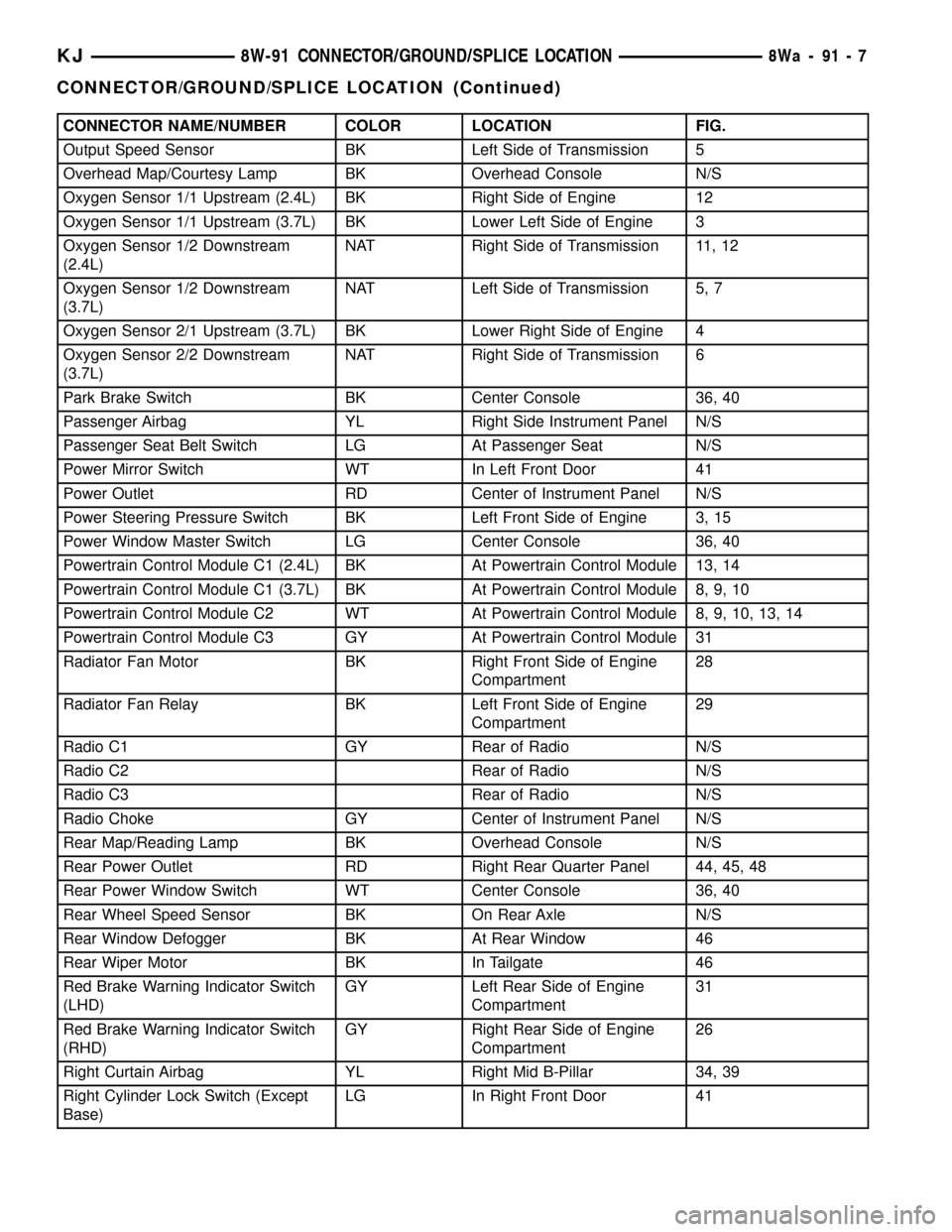
CONNECTOR NAME/NUMBER COLOR LOCATION FIG.
Output Speed Sensor BK Left Side of Transmission 5
Overhead Map/Courtesy Lamp BK Overhead Console N/S
Oxygen Sensor 1/1 Upstream (2.4L) BK Right Side of Engine 12
Oxygen Sensor 1/1 Upstream (3.7L) BK Lower Left Side of Engine 3
Oxygen Sensor 1/2 Downstream
(2.4L)NAT Right Side of Transmission 11, 12
Oxygen Sensor 1/2 Downstream
(3.7L)NAT Left Side of Transmission 5, 7
Oxygen Sensor 2/1 Upstream (3.7L) BK Lower Right Side of Engine 4
Oxygen Sensor 2/2 Downstream
(3.7L)NAT Right Side of Transmission 6
Park Brake Switch BK Center Console 36, 40
Passenger Airbag YL Right Side Instrument Panel N/S
Passenger Seat Belt Switch LG At Passenger Seat N/S
Power Mirror Switch WT In Left Front Door 41
Power Outlet RD Center of Instrument Panel N/S
Power Steering Pressure Switch BK Left Front Side of Engine 3, 15
Power Window Master Switch LG Center Console 36, 40
Powertrain Control Module C1 (2.4L) BK At Powertrain Control Module 13, 14
Powertrain Control Module C1 (3.7L) BK At Powertrain Control Module 8, 9, 10
Powertrain Control Module C2 WT At Powertrain Control Module 8, 9, 10, 13, 14
Powertrain Control Module C3 GY At Powertrain Control Module 31
Radiator Fan Motor BK Right Front Side of Engine
Compartment28
Radiator Fan Relay BK Left Front Side of Engine
Compartment29
Radio C1 GY Rear of Radio N/S
Radio C2 Rear of Radio N/S
Radio C3 Rear of Radio N/S
Radio Choke GY Center of Instrument Panel N/S
Rear Map/Reading Lamp BK Overhead Console N/S
Rear Power Outlet RD Right Rear Quarter Panel 44, 45, 48
Rear Power Window Switch WT Center Console 36, 40
Rear Wheel Speed Sensor BK On Rear Axle N/S
Rear Window Defogger BK At Rear Window 46
Rear Wiper Motor BK In Tailgate 46
Red Brake Warning Indicator Switch
(LHD)GY Left Rear Side of Engine
Compartment31
Red Brake Warning Indicator Switch
(RHD)GY Right Rear Side of Engine
Compartment26
Right Curtain Airbag YL Right Mid B-Pillar 34, 39
Right Cylinder Lock Switch (Except
Base)LG In Right Front Door 41
KJ8W-91 CONNECTOR/GROUND/SPLICE LOCATION8Wa-91-7
CONNECTOR/GROUND/SPLICE LOCATION (Continued)
Page 1163 of 1803
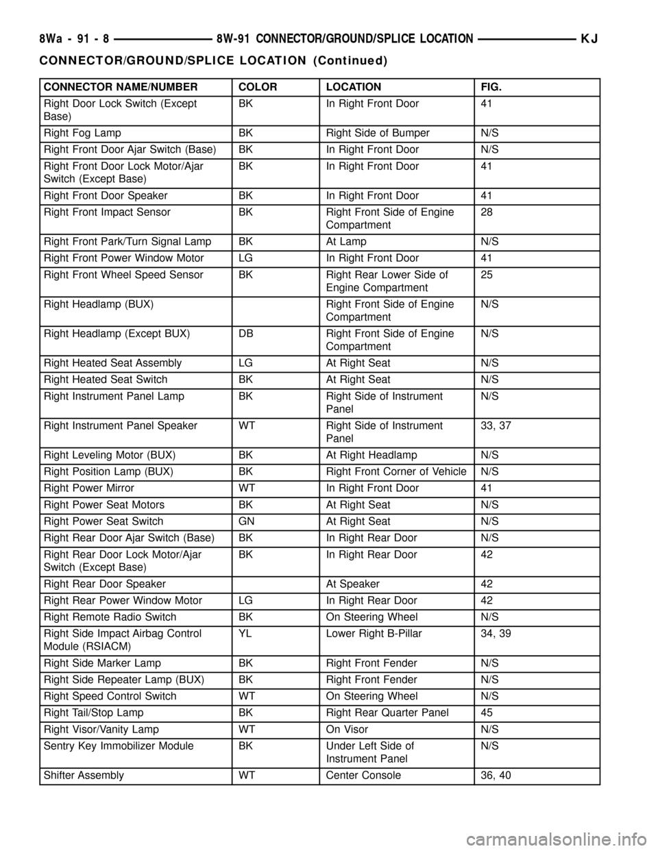
CONNECTOR NAME/NUMBER COLOR LOCATION FIG.
Right Door Lock Switch (Except
Base)BK In Right Front Door 41
Right Fog Lamp BK Right Side of Bumper N/S
Right Front Door Ajar Switch (Base) BK In Right Front Door N/S
Right Front Door Lock Motor/Ajar
Switch (Except Base)BK In Right Front Door 41
Right Front Door Speaker BK In Right Front Door 41
Right Front Impact Sensor BK Right Front Side of Engine
Compartment28
Right Front Park/Turn Signal Lamp BK At Lamp N/S
Right Front Power Window Motor LG In Right Front Door 41
Right Front Wheel Speed Sensor BK Right Rear Lower Side of
Engine Compartment25
Right Headlamp (BUX) Right Front Side of Engine
CompartmentN/S
Right Headlamp (Except BUX) DB Right Front Side of Engine
CompartmentN/S
Right Heated Seat Assembly LG At Right Seat N/S
Right Heated Seat Switch BK At Right Seat N/S
Right Instrument Panel Lamp BK Right Side of Instrument
PanelN/S
Right Instrument Panel Speaker WT Right Side of Instrument
Panel33, 37
Right Leveling Motor (BUX) BK At Right Headlamp N/S
Right Position Lamp (BUX) BK Right Front Corner of Vehicle N/S
Right Power Mirror WT In Right Front Door 41
Right Power Seat Motors BK At Right Seat N/S
Right Power Seat Switch GN At Right Seat N/S
Right Rear Door Ajar Switch (Base) BK In Right Rear Door N/S
Right Rear Door Lock Motor/Ajar
Switch (Except Base)BK In Right Rear Door 42
Right Rear Door Speaker At Speaker 42
Right Rear Power Window Motor LG In Right Rear Door 42
Right Remote Radio Switch BK On Steering Wheel N/S
Right Side Impact Airbag Control
Module (RSIACM)YL Lower Right B-Pillar 34, 39
Right Side Marker Lamp BK Right Front Fender N/S
Right Side Repeater Lamp (BUX) BK Right Front Fender N/S
Right Speed Control Switch WT On Steering Wheel N/S
Right Tail/Stop Lamp BK Right Rear Quarter Panel 45
Right Visor/Vanity Lamp WT On Visor N/S
Sentry Key Immobilizer Module BK Under Left Side of
Instrument PanelN/S
Shifter Assembly WT Center Console 36, 40
8Wa - 91 - 8 8W-91 CONNECTOR/GROUND/SPLICE LOCATIONKJ
CONNECTOR/GROUND/SPLICE LOCATION (Continued)
Page 1168 of 1803
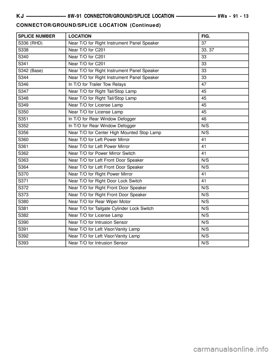
SPLICE NUMBER LOCATION FIG.
S336 (RHD) Near T/O for Right Instrument Panel Speaker 37
S338 Near T/O for C201 33, 37
S340 Near T/O for C201 33
S341 Near T/O for C201 33
S342 (Base) Near T/O for Right Instrument Panel Speaker 33
S344 Near T/O for Right Instrument Panel Speaker 33
S346 In T/O for Trailer Tow Relays 47
S347 Near T/O for Right Tail/Stop Lamp 45
S348 Near T/O for Right Tail/Stop Lamp 45
S349 Near T/O for License Lamp 45
S350 Near T/O for License Lamp 45
S351 In T/O for Rear Window Defogger 46
S352 In T/O for Rear Window Defogger N/S
S356 Near T/O for Center High Mounted Stop Lamp N/S
S360 Near T/O for Left Power Mirror 41
S361 Near T/O for Left Power Mirror 41
S362 Near T/O for Power Mirror Switch 41
S363 Near T/O for Left Front Door Speaker N/S
S364 Near T/O for Left Front Door Speaker N/S
S370 Near T/O for Right Power Mirror 41
S371 Near T/O for Right Door Lock Switch 41
S372 Near T/O for Right Front Door Speaker N/S
S373 Near T/O for Right Front Door Speaker N/S
S380 Near T/O for Rear Wiper Motor N/S
S381 Near T/O for Tailgate Cylinder Lock Switch N/S
S382 Near T/O for License Lamp N/S
S390 Near T/O for Intrusion Sensor N/S
S391 Near T/O for Left Visor/Vanity Lamp N/S
S392 Near T/O for Left Visor/Vanity Lamp N/S
S393 Near T/O for Intrusion Sensor N/S
KJ8W-91 CONNECTOR/GROUND/SPLICE LOCATION8Wa-91-13
CONNECTOR/GROUND/SPLICE LOCATION (Continued)
Page 1208 of 1803
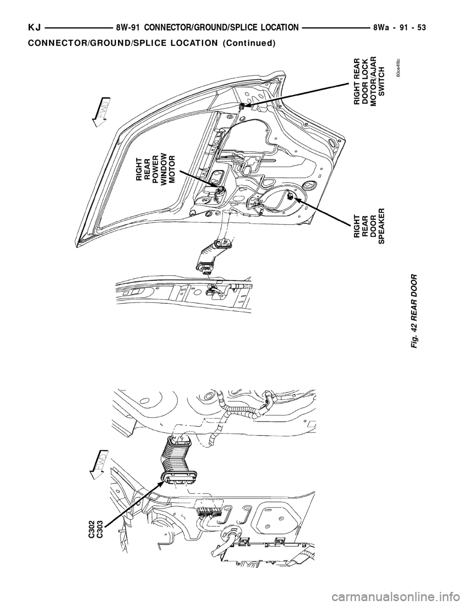
Fig. 42 REAR DOOR
KJ8W-91 CONNECTOR/GROUND/SPLICE LOCATION8Wa-91-53
CONNECTOR/GROUND/SPLICE LOCATION (Continued)
Page 1466 of 1803
BODY
TABLE OF CONTENTS
page page
BODY
WARNING
SAFETY PRECAUTIONS AND WARNINGS . . . 1
DIAGNOSIS AND TESTING
DIAGNOSIS AND TESTING - WATER LEAKS . 2
DIAGNOSIS AND TESTING - WIND NOISE . . . 3
STANDARD PROCEDURE
STANDARD PROCEDURE - BODY
LUBRICATION.........................3
STANDARD PROCEDURE - HEAT STAKING . . 3
SPECIFICATIONS........................4
SPECIAL TOOLS
BODY...............................5BODY STRUCTURE.......................6
HOOD................................119
DOOR - FRONT........................121
DOORS - REAR........................128
SWING GATE..........................135
EXTERIOR............................140
INSTRUMENT PANEL....................147
INTERIOR.............................156
PAINT................................162
SEATS...............................164
STATIONARY GLASS....................172
SUNROOF.............................175
WEATHERSTRIP/SEALS..................185
BODY
WARNING
SAFETY PRECAUTIONS AND WARNINGS
WARNING: EYE PROTECTION SHOULD BE USED
WHEN SERVICING GLASS COMPONENTS. PER-
SONAL INJURY CAN RESULT.
²USE A OSHA APPROVED BREATHING FILTER
WHEN SPRAYING PAINT OR SOLVENTS IN A CON-
FINED AREA. PERSONAL INJURY CAN RESULT.
²AVOID PROLONGED SKIN CONTACT WITH
PETROLEUM OR ALCOHOL±BASED CLEANING
SOLVENTS. PERSONAL INJURY CAN RESULT.
²DO NOT STAND UNDER A HOISTED VEHICLE
THAT IS NOT PROPERLY SUPPORTED ON SAFETY
STANDS. PERSONAL INJURY CAN RESULT.
CAUTION: When holes must be drilled or punched
in an inner body panel, verify depth of space to the
outer body panel, electrical wiring, or other compo-
nents. Damage to vehicle can result.
²Do not weld exterior panels unless combustible
material on the interior of vehicle is removed from
the repair area. Fire or hazardous conditions, can
result.
²Always have a fire extinguisher ready for use
when welding.
²Disconnect the negative (-) cable clamp from
the battery when servicing electrical components
that are live when the ignition is OFF. Damage to
electrical system can result.²Do not use abrasive chemicals or compounds
on painted surfaces. Damage to finish can result.
²Do not use harsh alkaline based cleaning sol-
vents on painted or upholstered surfaces. Damage
to finish or color can result.
²Do not hammer or pound on plastic trim panel
when servicing interior trim. Plastic panels can
break.
DaimlerChrysler Corporation uses many different
types of push-in fasteners to secure the interior and
exterior trim to the body. Most of these fasteners can
be reused to assemble the trim during various repair
procedures. At times, a push-in fastener cannot be
removed without damaging the fastener or the com-
ponent it is holding. If it is not possible to remove a
fastener without damaging a component or body, cut
or break the fastener and use a new one when
installing the component. Never pry or pound on a
plastic or pressed-board trim component. Using a
suitable fork-type prying device, pry the fastener
from the retaining hole behind the component being
removed. When installing, verify fastener alignment
with the retaining hole by hand. Push directly on or
over the fastener until it seats. Apply a low-force pull
to the panel to verify that it is secure.
When it is necessary to remove components to ser-
vice another, it should not be necessary to apply
excessive force or bend a component to remove it.
Before damaging a trim component, verify hidden
fasteners or captured edges holding the component in
place.
KJBODY 23 - 1
Page 1469 of 1803
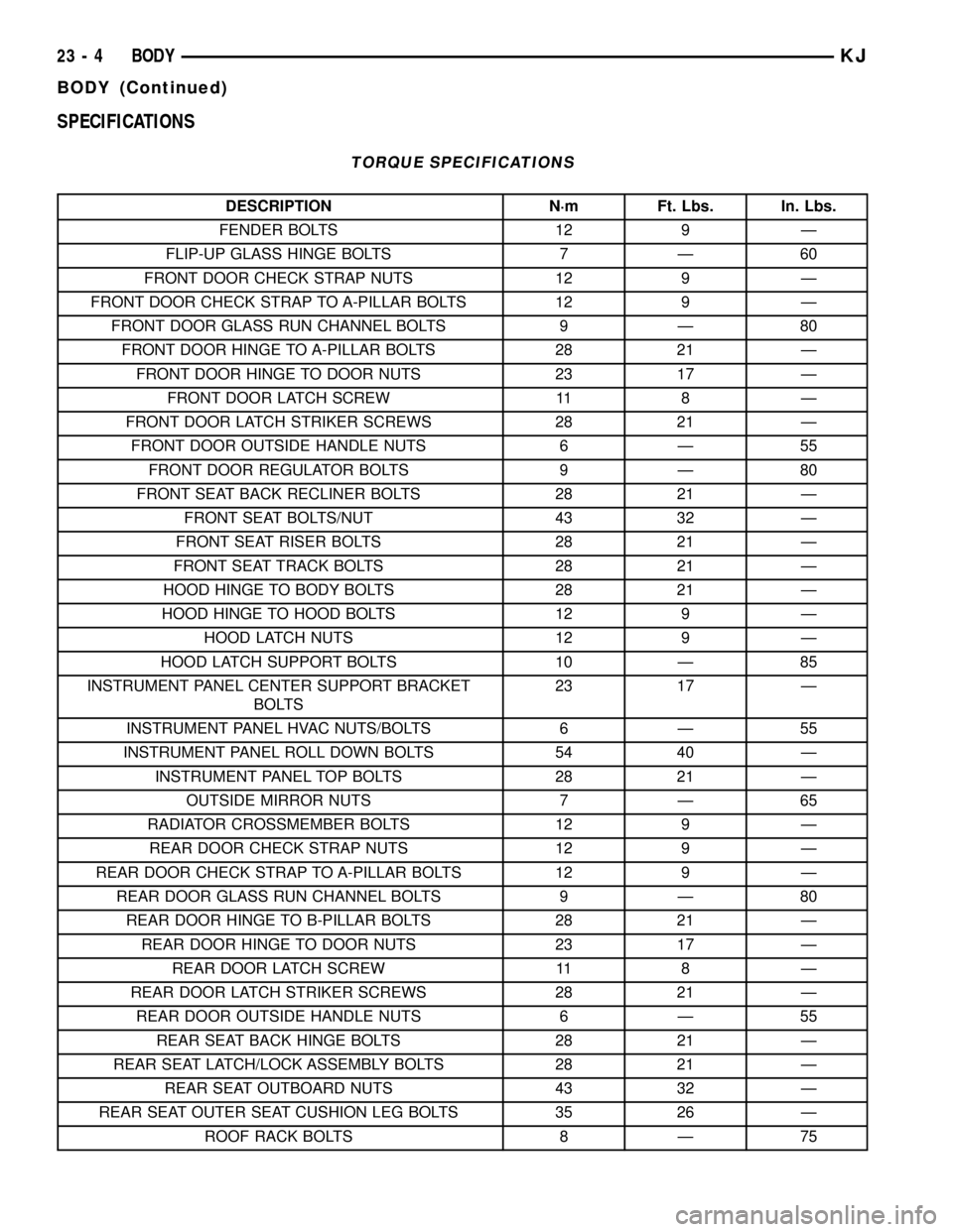
SPECIFICATIONS
TORQUE SPECIFICATIONS
DESCRIPTION N´m Ft. Lbs. In. Lbs.
FENDER BOLTS 12 9 Ð
FLIP-UP GLASS HINGE BOLTS 7 Ð 60
FRONT DOOR CHECK STRAP NUTS 12 9 Ð
FRONT DOOR CHECK STRAP TO A-PILLAR BOLTS 12 9 Ð
FRONT DOOR GLASS RUN CHANNEL BOLTS 9 Ð 80
FRONT DOOR HINGE TO A-PILLAR BOLTS 28 21 Ð
FRONT DOOR HINGE TO DOOR NUTS 23 17 Ð
FRONT DOOR LATCH SCREW 11 8 Ð
FRONT DOOR LATCH STRIKER SCREWS 28 21 Ð
FRONT DOOR OUTSIDE HANDLE NUTS 6 Ð 55
FRONT DOOR REGULATOR BOLTS 9 Ð 80
FRONT SEAT BACK RECLINER BOLTS 28 21 Ð
FRONT SEAT BOLTS/NUT 43 32 Ð
FRONT SEAT RISER BOLTS 28 21 Ð
FRONT SEAT TRACK BOLTS 28 21 Ð
HOOD HINGE TO BODY BOLTS 28 21 Ð
HOOD HINGE TO HOOD BOLTS 12 9 Ð
HOOD LATCH NUTS 12 9 Ð
HOOD LATCH SUPPORT BOLTS 10 Ð 85
INSTRUMENT PANEL CENTER SUPPORT BRACKET
BOLTS23 17 Ð
INSTRUMENT PANEL HVAC NUTS/BOLTS 6 Ð 55
INSTRUMENT PANEL ROLL DOWN BOLTS 54 40 Ð
INSTRUMENT PANEL TOP BOLTS 28 21 Ð
OUTSIDE MIRROR NUTS 7 Ð 65
RADIATOR CROSSMEMBER BOLTS 12 9 Ð
REAR DOOR CHECK STRAP NUTS 12 9 Ð
REAR DOOR CHECK STRAP TO A-PILLAR BOLTS 12 9 Ð
REAR DOOR GLASS RUN CHANNEL BOLTS 9 Ð 80
REAR DOOR HINGE TO B-PILLAR BOLTS 28 21 Ð
REAR DOOR HINGE TO DOOR NUTS 23 17 Ð
REAR DOOR LATCH SCREW 11 8 Ð
REAR DOOR LATCH STRIKER SCREWS 28 21 Ð
REAR DOOR OUTSIDE HANDLE NUTS 6 Ð 55
REAR SEAT BACK HINGE BOLTS 28 21 Ð
REAR SEAT LATCH/LOCK ASSEMBLY BOLTS 28 21 Ð
REAR SEAT OUTBOARD NUTS 43 32 Ð
REAR SEAT OUTER SEAT CUSHION LEG BOLTS 35 26 Ð
ROOF RACK BOLTS 8 Ð 75
23 - 4 BODYKJ
BODY (Continued)
Page 1552 of 1803
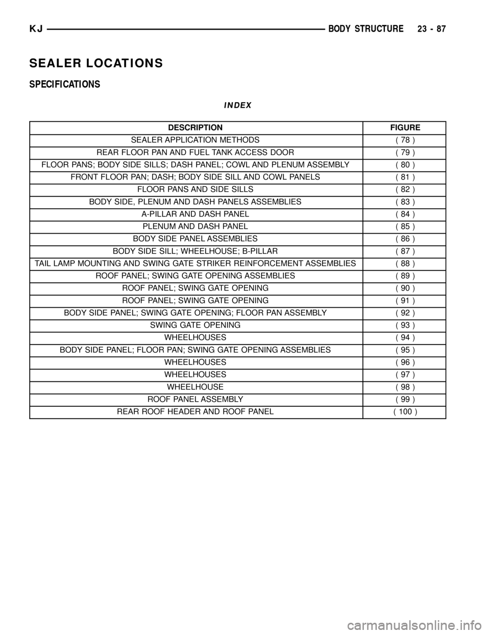
SEALER LOCATIONS
SPECIFICATIONS
INDEX
DESCRIPTION FIGURE
SEALER APPLICATION METHODS ( 78 )
REAR FLOOR PAN AND FUEL TANK ACCESS DOOR ( 79 )
FLOOR PANS; BODY SIDE SILLS; DASH PANEL; COWL AND PLENUM ASSEMBLY ( 80 )
FRONT FLOOR PAN; DASH; BODY SIDE SILL AND COWL PANELS ( 81 )
FLOOR PANS AND SIDE SILLS ( 82 )
BODY SIDE, PLENUM AND DASH PANELS ASSEMBLIES ( 83 )
A-PILLAR AND DASH PANEL ( 84 )
PLENUM AND DASH PANEL ( 85 )
BODY SIDE PANEL ASSEMBLIES ( 86 )
BODY SIDE SILL; WHEELHOUSE; B-PILLAR ( 87 )
TAIL LAMP MOUNTING AND SWING GATE STRIKER REINFORCEMENT ASSEMBLIES ( 88 )
ROOF PANEL; SWING GATE OPENING ASSEMBLIES ( 89 )
ROOF PANEL; SWING GATE OPENING ( 90 )
ROOF PANEL; SWING GATE OPENING ( 91 )
BODY SIDE PANEL; SWING GATE OPENING; FLOOR PAN ASSEMBLY ( 92 )
SWING GATE OPENING ( 93 )
WHEELHOUSES ( 94 )
BODY SIDE PANEL; FLOOR PAN; SWING GATE OPENING ASSEMBLIES ( 95 )
WHEELHOUSES ( 96 )
WHEELHOUSES ( 97 )
WHEELHOUSE ( 98 )
ROOF PANEL ASSEMBLY ( 99 )
REAR ROOF HEADER AND ROOF PANEL ( 100 )
KJBODY STRUCTURE 23 - 87
Page 1588 of 1803
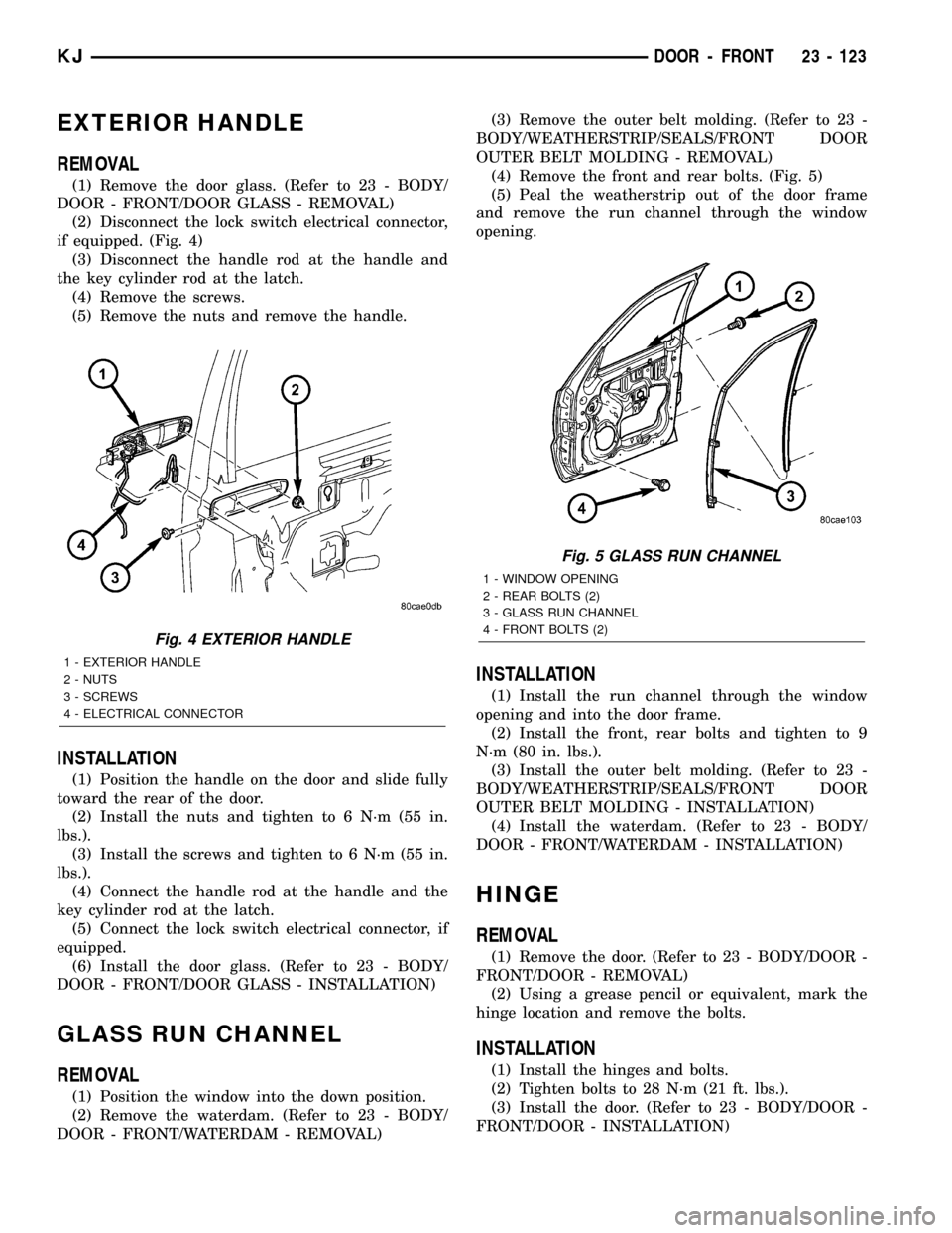
EXTERIOR HANDLE
REMOVAL
(1) Remove the door glass. (Refer to 23 - BODY/
DOOR - FRONT/DOOR GLASS - REMOVAL)
(2) Disconnect the lock switch electrical connector,
if equipped. (Fig. 4)
(3) Disconnect the handle rod at the handle and
the key cylinder rod at the latch.
(4) Remove the screws.
(5) Remove the nuts and remove the handle.
INSTALLATION
(1) Position the handle on the door and slide fully
toward the rear of the door.
(2) Install the nuts and tighten to 6 N´m (55 in.
lbs.).
(3) Install the screws and tighten to 6 N´m (55 in.
lbs.).
(4) Connect the handle rod at the handle and the
key cylinder rod at the latch.
(5) Connect the lock switch electrical connector, if
equipped.
(6) Install the door glass. (Refer to 23 - BODY/
DOOR - FRONT/DOOR GLASS - INSTALLATION)
GLASS RUN CHANNEL
REMOVAL
(1) Position the window into the down position.
(2) Remove the waterdam. (Refer to 23 - BODY/
DOOR - FRONT/WATERDAM - REMOVAL)(3) Remove the outer belt molding. (Refer to 23 -
BODY/WEATHERSTRIP/SEALS/FRONT DOOR
OUTER BELT MOLDING - REMOVAL)
(4) Remove the front and rear bolts. (Fig. 5)
(5) Peal the weatherstrip out of the door frame
and remove the run channel through the window
opening.
INSTALLATION
(1) Install the run channel through the window
opening and into the door frame.
(2) Install the front, rear bolts and tighten to 9
N´m (80 in. lbs.).
(3) Install the outer belt molding. (Refer to 23 -
BODY/WEATHERSTRIP/SEALS/FRONT DOOR
OUTER BELT MOLDING - INSTALLATION)
(4) Install the waterdam. (Refer to 23 - BODY/
DOOR - FRONT/WATERDAM - INSTALLATION)
HINGE
REMOVAL
(1) Remove the door. (Refer to 23 - BODY/DOOR -
FRONT/DOOR - REMOVAL)
(2) Using a grease pencil or equivalent, mark the
hinge location and remove the bolts.
INSTALLATION
(1) Install the hinges and bolts.
(2) Tighten bolts to 28 N´m (21 ft. lbs.).
(3) Install the door. (Refer to 23 - BODY/DOOR -
FRONT/DOOR - INSTALLATION)
Fig. 4 EXTERIOR HANDLE
1 - EXTERIOR HANDLE
2 - NUTS
3 - SCREWS
4 - ELECTRICAL CONNECTOR
Fig. 5 GLASS RUN CHANNEL
1 - WINDOW OPENING
2 - REAR BOLTS (2)
3 - GLASS RUN CHANNEL
4 - FRONT BOLTS (2)
KJDOOR - FRONT 23 - 123