2002 JEEP LIBERTY engine coolant
[x] Cancel search: engine coolantPage 1110 of 1803
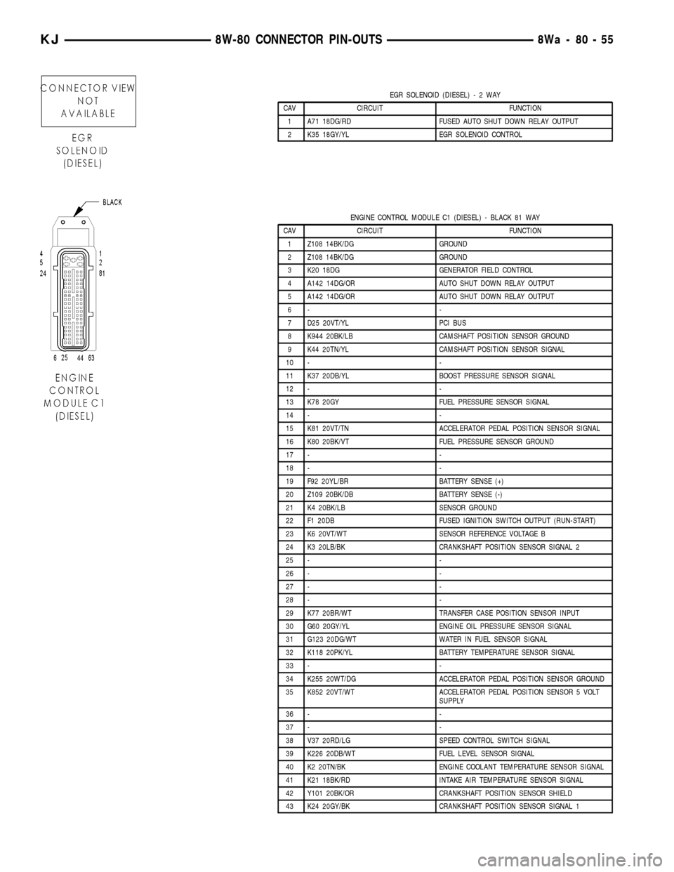
EGR SOLENOID (DIESEL)-2WAY
CAV CIRCUIT FUNCTION
1 A71 18DG/RD FUSED AUTO SHUT DOWN RELAY OUTPUT
2 K35 18GY/YL EGR SOLENOID CONTROL
ENGINE CONTROL MODULE C1 (DIESEL) - BLACK 81 WAY
CAV CIRCUIT FUNCTION
1 Z108 14BK/DG GROUND
2 Z108 14BK/DG GROUND
3 K20 18DG GENERATOR FIELD CONTROL
4 A142 14DG/OR AUTO SHUT DOWN RELAY OUTPUT
5 A142 14DG/OR AUTO SHUT DOWN RELAY OUTPUT
6- -
7 D25 20VT/YL PCI BUS
8 K944 20BK/LB CAMSHAFT POSITION SENSOR GROUND
9 K44 20TN/YL CAMSHAFT POSITION SENSOR SIGNAL
10 - -
11 K37 20DB/YL BOOST PRESSURE SENSOR SIGNAL
12 - -
13 K78 20GY FUEL PRESSURE SENSOR SIGNAL
14 - -
15 K81 20VT/TN ACCELERATOR PEDAL POSITION SENSOR SIGNAL
16 K80 20BK/VT FUEL PRESSURE SENSOR GROUND
17 - -
18 - -
19 F92 20YL/BR BATTERY SENSE (+)
20 Z109 20BK/DB BATTERY SENSE (-)
21 K4 20BK/LB SENSOR GROUND
22 F1 20DB FUSED IGNITION SWITCH OUTPUT (RUN-START)
23 K6 20VT/WT SENSOR REFERENCE VOLTAGE B
24 K3 20LB/BK CRANKSHAFT POSITION SENSOR SIGNAL 2
25 - -
26 - -
27 - -
28 - -
29 K77 20BR/WT TRANSFER CASE POSITION SENSOR INPUT
30 G60 20GY/YL ENGINE OIL PRESSURE SENSOR SIGNAL
31 G123 20DG/WT WATER IN FUEL SENSOR SIGNAL
32 K118 20PK/YL BATTERY TEMPERATURE SENSOR SIGNAL
33 - -
34 K255 20WT/DG ACCELERATOR PEDAL POSITION SENSOR GROUND
35 K852 20VT/WT ACCELERATOR PEDAL POSITION SENSOR 5 VOLT
SUPPLY
36 - -
37 - -
38 V37 20RD/LG SPEED CONTROL SWITCH SIGNAL
39 K226 20DB/WT FUEL LEVEL SENSOR SIGNAL
40 K2 20TN/BK ENGINE COOLANT TEMPERATURE SENSOR SIGNAL
41 K21 18BK/RD INTAKE AIR TEMPERATURE SENSOR SIGNAL
42 Y101 20BK/OR CRANKSHAFT POSITION SENSOR SHIELD
43 K24 20GY/BK CRANKSHAFT POSITION SENSOR SIGNAL 1
KJ8W-80 CONNECTOR PIN-OUTS8Wa-80-55
Page 1112 of 1803
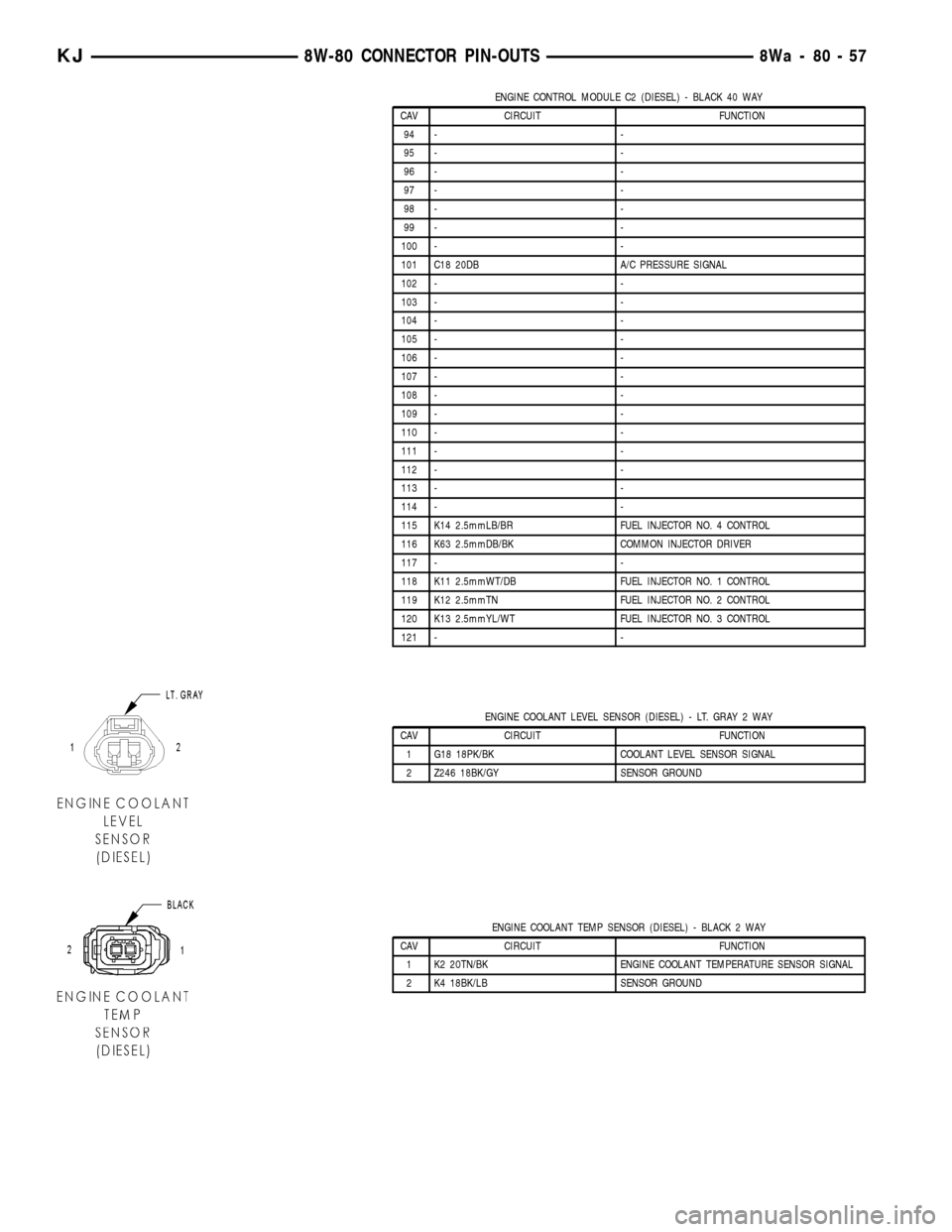
ENGINE CONTROL MODULE C2 (DIESEL) - BLACK 40 WAY
CAV CIRCUIT FUNCTION
94 - -
95 - -
96 - -
97 - -
98 - -
99 - -
100 - -
101 C18 20DB A/C PRESSURE SIGNAL
102 - -
103 - -
104 - -
105 - -
106 - -
107 - -
108 - -
109 - -
110 - -
111 - -
112 - -
113 - -
114 - -
115 K14 2.5mmLB/BR FUEL INJECTOR NO. 4 CONTROL
116 K63 2.5mmDB/BK COMMON INJECTOR DRIVER
117 - -
118 K11 2.5mmWT/DB FUEL INJECTOR NO. 1 CONTROL
119 K12 2.5mmTN FUEL INJECTOR NO. 2 CONTROL
120 K13 2.5mmYL/WT FUEL INJECTOR NO. 3 CONTROL
121 - -
ENGINE COOLANT LEVEL SENSOR (DIESEL) - LT. GRAY 2 WAY
CAV CIRCUIT FUNCTION
1 G18 18PK/BK COOLANT LEVEL SENSOR SIGNAL
2 Z246 18BK/GY SENSOR GROUND
ENGINE COOLANT TEMP SENSOR (DIESEL) - BLACK 2 WAY
CAV CIRCUIT FUNCTION
1 K2 20TN/BK ENGINE COOLANT TEMPERATURE SENSOR SIGNAL
2 K4 18BK/LB SENSOR GROUND
KJ8W-80 CONNECTOR PIN-OUTS8Wa-80-57
Page 1113 of 1803
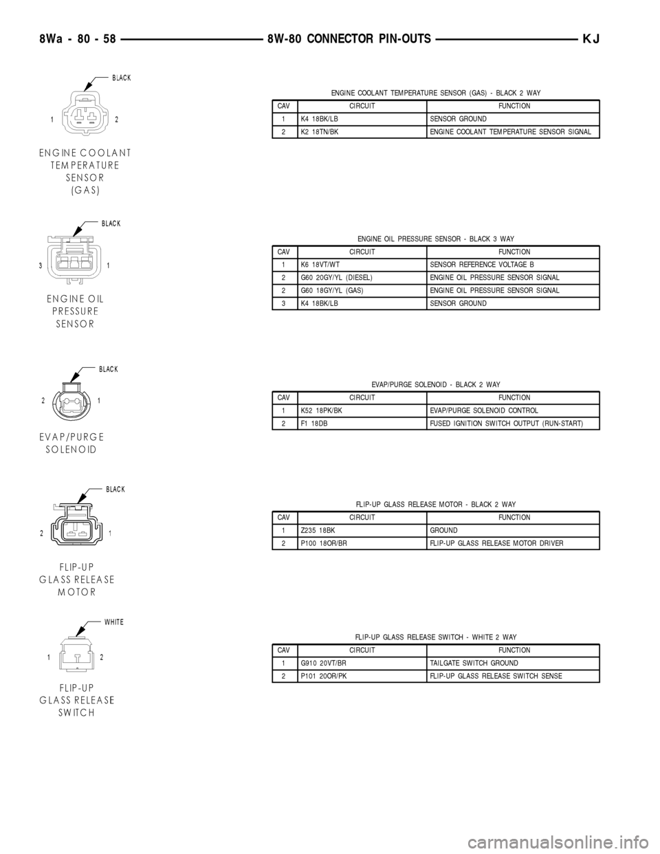
ENGINE COOLANT TEMPERATURE SENSOR (GAS) - BLACK 2 WAY
CAV CIRCUIT FUNCTION
1 K4 18BK/LB SENSOR GROUND
2 K2 18TN/BK ENGINE COOLANT TEMPERATURE SENSOR SIGNAL
ENGINE OIL PRESSURE SENSOR - BLACK 3 WAY
CAV CIRCUIT FUNCTION
1 K6 18VT/WT SENSOR REFERENCE VOLTAGE B
2 G60 20GY/YL (DIESEL) ENGINE OIL PRESSURE SENSOR SIGNAL
2 G60 18GY/YL (GAS) ENGINE OIL PRESSURE SENSOR SIGNAL
3 K4 18BK/LB SENSOR GROUND
EVAP/PURGE SOLENOID - BLACK 2 WAY
CAV CIRCUIT FUNCTION
1 K52 18PK/BK EVAP/PURGE SOLENOID CONTROL
2 F1 18DB FUSED IGNITION SWITCH OUTPUT (RUN-START)
FLIP-UP GLASS RELEASE MOTOR - BLACK 2 WAY
CAV CIRCUIT FUNCTION
1 Z235 18BK GROUND
2 P100 18OR/BR FLIP-UP GLASS RELEASE MOTOR DRIVER
FLIP-UP GLASS RELEASE SWITCH - WHITE 2 WAY
CAV CIRCUIT FUNCTION
1 G910 20VT/BR TAILGATE SWITCH GROUND
2 P101 20OR/PK FLIP-UP GLASS RELEASE SWITCH SENSE
8Wa - 80 - 58 8W-80 CONNECTOR PIN-OUTSKJ
Page 1136 of 1803
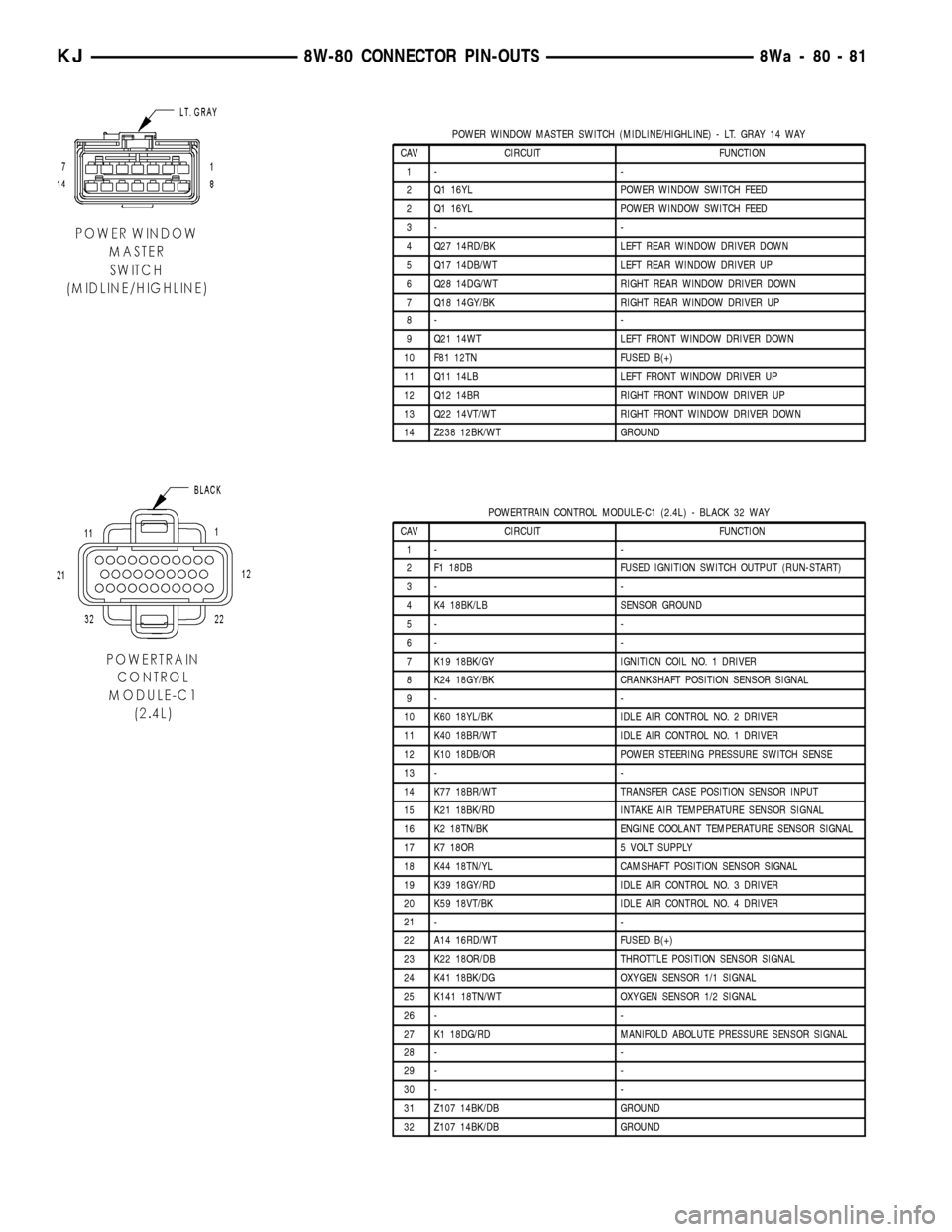
POWER WINDOW MASTER SWITCH (MIDLINE/HIGHLINE) - LT. GRAY 14 WAY
CAV CIRCUIT FUNCTION
1- -
2 Q1 16YL POWER WINDOW SWITCH FEED
2 Q1 16YL POWER WINDOW SWITCH FEED
3- -
4 Q27 14RD/BK LEFT REAR WINDOW DRIVER DOWN
5 Q17 14DB/WT LEFT REAR WINDOW DRIVER UP
6 Q28 14DG/WT RIGHT REAR WINDOW DRIVER DOWN
7 Q18 14GY/BK RIGHT REAR WINDOW DRIVER UP
8- -
9 Q21 14WT LEFT FRONT WINDOW DRIVER DOWN
10 F81 12TN FUSED B(+)
11 Q11 14LB LEFT FRONT WINDOW DRIVER UP
12 Q12 14BR RIGHT FRONT WINDOW DRIVER UP
13 Q22 14VT/WT RIGHT FRONT WINDOW DRIVER DOWN
14 Z238 12BK/WT GROUND
POWERTRAIN CONTROL MODULE-C1 (2.4L) - BLACK 32 WAY
CAV CIRCUIT FUNCTION
1- -
2 F1 18DB FUSED IGNITION SWITCH OUTPUT (RUN-START)
3- -
4 K4 18BK/LB SENSOR GROUND
5- -
6- -
7 K19 18BK/GY IGNITION COIL NO. 1 DRIVER
8 K24 18GY/BK CRANKSHAFT POSITION SENSOR SIGNAL
9- -
10 K60 18YL/BK IDLE AIR CONTROL NO. 2 DRIVER
11 K40 18BR/WT IDLE AIR CONTROL NO. 1 DRIVER
12 K10 18DB/OR POWER STEERING PRESSURE SWITCH SENSE
13 - -
14 K77 18BR/WT TRANSFER CASE POSITION SENSOR INPUT
15 K21 18BK/RD INTAKE AIR TEMPERATURE SENSOR SIGNAL
16 K2 18TN/BK ENGINE COOLANT TEMPERATURE SENSOR SIGNAL
17 K7 18OR 5 VOLT SUPPLY
18 K44 18TN/YL CAMSHAFT POSITION SENSOR SIGNAL
19 K39 18GY/RD IDLE AIR CONTROL NO. 3 DRIVER
20 K59 18VT/BK IDLE AIR CONTROL NO. 4 DRIVER
21 - -
22 A14 16RD/WT FUSED B(+)
23 K22 18OR/DB THROTTLE POSITION SENSOR SIGNAL
24 K41 18BK/DG OXYGEN SENSOR 1/1 SIGNAL
25 K141 18TN/WT OXYGEN SENSOR 1/2 SIGNAL
26 - -
27 K1 18DG/RD MANIFOLD ABOLUTE PRESSURE SENSOR SIGNAL
28 - -
29 - -
30 - -
31 Z107 14BK/DB GROUND
32 Z107 14BK/DB GROUND
KJ8W-80 CONNECTOR PIN-OUTS8Wa-80-81
Page 1137 of 1803
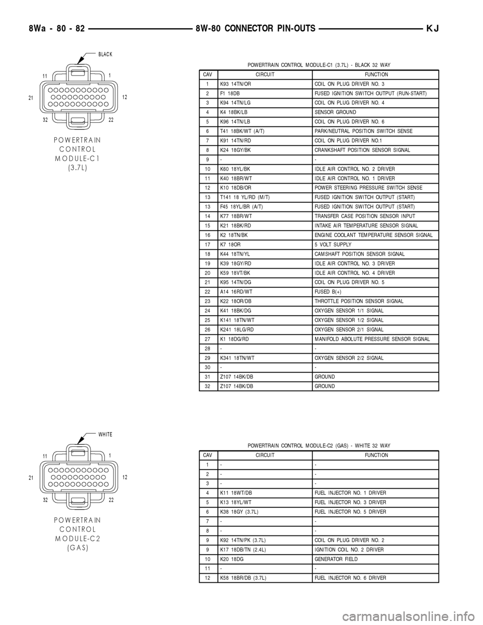
POWERTRAIN CONTROL MODULE-C1 (3.7L) - BLACK 32 WAY
CAV CIRCUIT FUNCTION
1 K93 14TN/OR COIL ON PLUG DRIVER NO. 3
2 F1 18DB FUSED IGNITION SWITCH OUTPUT (RUN-START)
3 K94 14TN/LG COIL ON PLUG DRIVER NO. 4
4 K4 18BK/LB SENSOR GROUND
5 K96 14TN/LB COIL ON PLUG DRIVER NO. 6
6 T41 18BK/WT (A/T) PARK/NEUTRAL POSITION SWITCH SENSE
7 K91 14TN/RD COIL ON PLUG DRIVER NO.1
8 K24 18GY/BK CRANKSHAFT POSITION SENSOR SIGNAL
9- -
10 K60 18YL/BK IDLE AIR CONTROL NO. 2 DRIVER
11 K40 18BR/WT IDLE AIR CONTROL NO. 1 DRIVER
12 K10 18DB/OR POWER STEERING PRESSURE SWITCH SENSE
13 T141 18 YL/RD (M/T) FUSED IGNITION SWITCH OUTPUT (START)
13 F45 18YL/BR (A/T) FUSED IGNITION SWITCH OUTPUT (START)
14 K77 18BR/WT TRANSFER CASE POSITION SENSOR INPUT
15 K21 18BK/RD INTAKE AIR TEMPERATURE SENSOR SIGNAL
16 K2 18TN/BK ENGINE COOLANT TEMPERATURE SENSOR SIGNAL
17 K7 18OR 5 VOLT SUPPLY
18 K44 18TN/YL CAMSHAFT POSITION SENSOR SIGNAL
19 K39 18GY/RD IDLE AIR CONTROL NO. 3 DRIVER
20 K59 18VT/BK IDLE AIR CONTROL NO. 4 DRIVER
21 K95 14TN/DG COIL ON PLUG DRIVER NO. 5
22 A14 16RD/WT FUSED B(+)
23 K22 18OR/DB THROTTLE POSITION SENSOR SIGNAL
24 K41 18BK/DG OXYGEN SENSOR 1/1 SIGNAL
25 K141 18TN/WT OXYGEN SENSOR 1/2 SIGNAL
26 K241 18LG/RD OXYGEN SENSOR 2/1 SIGNAL
27 K1 18DG/RD MANIFOLD ABOLUTE PRESSURE SENSOR SIGNAL
28 - -
29 K341 18TN/WT OXYGEN SENSOR 2/2 SIGNAL
30 - -
31 Z107 14BK/DB GROUND
32 Z107 14BK/DB GROUND
POWERTRAIN CONTROL MODULE-C2 (GAS) - WHITE 32 WAY
CAV CIRCUIT FUNCTION
1- -
2- -
3- -
4 K11 18WT/DB FUEL INJECTOR NO. 1 DRIVER
5 K13 18YL/WT FUEL INJECTOR NO. 3 DRIVER
6 K38 18GY (3.7L) FUEL INJECTOR NO. 5 DRIVER
7- -
8- -
9 K92 14TN/PK (3.7L) COIL ON PLUG DRIVER NO. 2
9 K17 18DB/TN (2.4L) IGNITION COIL NO. 2 DRIVER
10 K20 18DG GENERATOR FIELD
11 - -
12 K58 18BR/DB (3.7L) FUEL INJECTOR NO. 6 DRIVER
8Wa - 80 - 82 8W-80 CONNECTOR PIN-OUTSKJ
Page 1159 of 1803
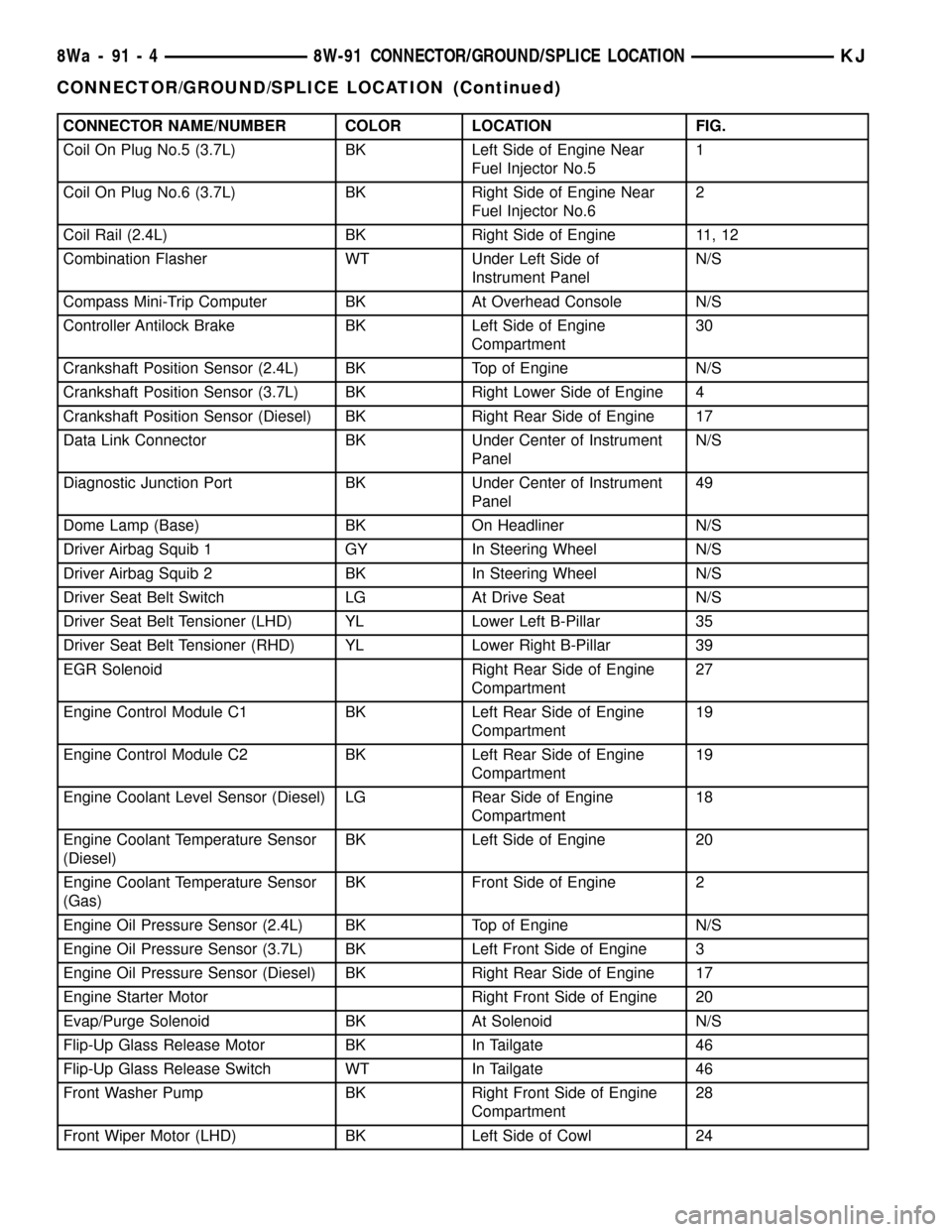
CONNECTOR NAME/NUMBER COLOR LOCATION FIG.
Coil On Plug No.5 (3.7L) BK Left Side of Engine Near
Fuel Injector No.51
Coil On Plug No.6 (3.7L) BK Right Side of Engine Near
Fuel Injector No.62
Coil Rail (2.4L) BK Right Side of Engine 11, 12
Combination Flasher WT Under Left Side of
Instrument PanelN/S
Compass Mini-Trip Computer BK At Overhead Console N/S
Controller Antilock Brake BK Left Side of Engine
Compartment30
Crankshaft Position Sensor (2.4L) BK Top of Engine N/S
Crankshaft Position Sensor (3.7L) BK Right Lower Side of Engine 4
Crankshaft Position Sensor (Diesel) BK Right Rear Side of Engine 17
Data Link Connector BK Under Center of Instrument
PanelN/S
Diagnostic Junction Port BK Under Center of Instrument
Panel49
Dome Lamp (Base) BK On Headliner N/S
Driver Airbag Squib 1 GY In Steering Wheel N/S
Driver Airbag Squib 2 BK In Steering Wheel N/S
Driver Seat Belt Switch LG At Drive Seat N/S
Driver Seat Belt Tensioner (LHD) YL Lower Left B-Pillar 35
Driver Seat Belt Tensioner (RHD) YL Lower Right B-Pillar 39
EGR Solenoid Right Rear Side of Engine
Compartment27
Engine Control Module C1 BK Left Rear Side of Engine
Compartment19
Engine Control Module C2 BK Left Rear Side of Engine
Compartment19
Engine Coolant Level Sensor (Diesel) LG Rear Side of Engine
Compartment18
Engine Coolant Temperature Sensor
(Diesel)BK Left Side of Engine 20
Engine Coolant Temperature Sensor
(Gas)BK Front Side of Engine 2
Engine Oil Pressure Sensor (2.4L) BK Top of Engine N/S
Engine Oil Pressure Sensor (3.7L) BK Left Front Side of Engine 3
Engine Oil Pressure Sensor (Diesel) BK Right Rear Side of Engine 17
Engine Starter Motor Right Front Side of Engine 20
Evap/Purge Solenoid BK At Solenoid N/S
Flip-Up Glass Release Motor BK In Tailgate 46
Flip-Up Glass Release Switch WT In Tailgate 46
Front Washer Pump BK Right Front Side of Engine
Compartment28
Front Wiper Motor (LHD) BK Left Side of Cowl 24
8Wa - 91 - 4 8W-91 CONNECTOR/GROUND/SPLICE LOCATIONKJ
CONNECTOR/GROUND/SPLICE LOCATION (Continued)
Page 1223 of 1803
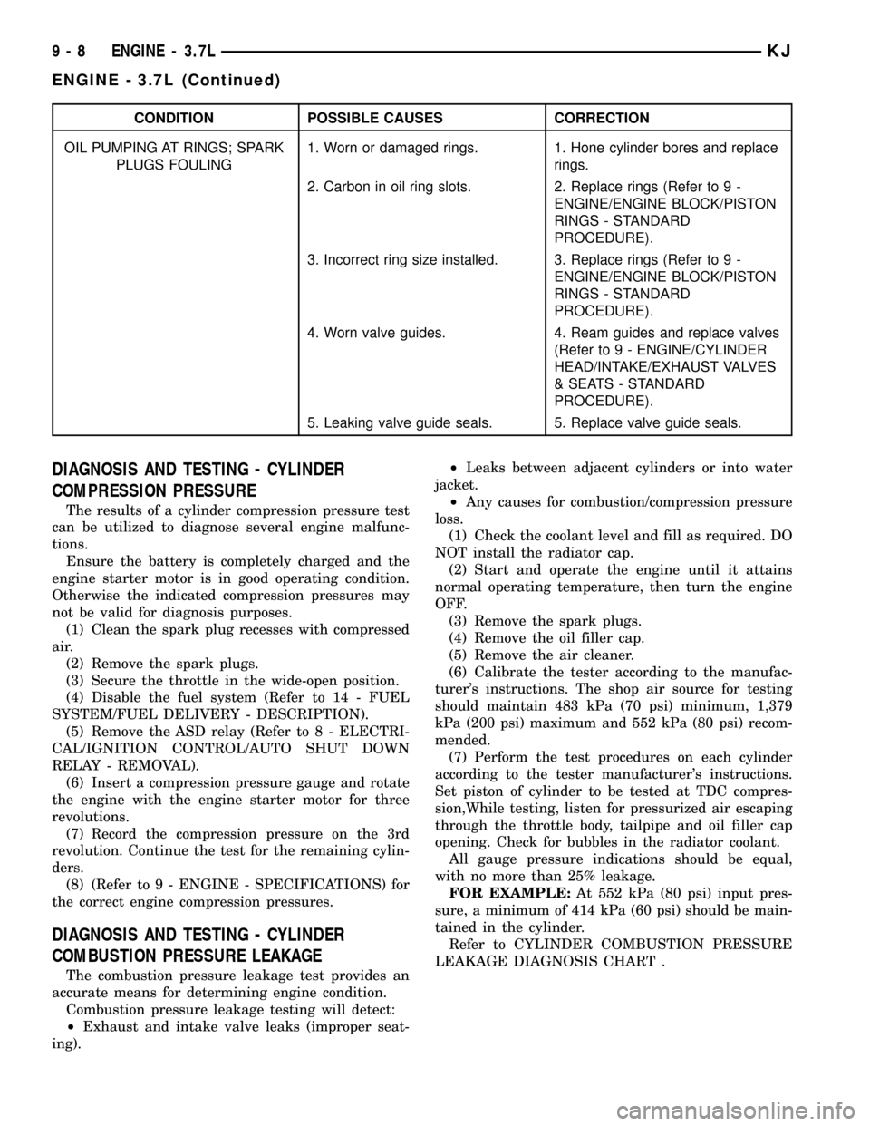
CONDITION POSSIBLE CAUSES CORRECTION
OIL PUMPING AT RINGS; SPARK
PLUGS FOULING1. Worn or damaged rings. 1. Hone cylinder bores and replace
rings.
2. Carbon in oil ring slots. 2. Replace rings (Refer to 9 -
ENGINE/ENGINE BLOCK/PISTON
RINGS - STANDARD
PROCEDURE).
3. Incorrect ring size installed. 3. Replace rings (Refer to 9 -
ENGINE/ENGINE BLOCK/PISTON
RINGS - STANDARD
PROCEDURE).
4. Worn valve guides. 4. Ream guides and replace valves
(Refer to 9 - ENGINE/CYLINDER
HEAD/INTAKE/EXHAUST VALVES
& SEATS - STANDARD
PROCEDURE).
5. Leaking valve guide seals. 5. Replace valve guide seals.
DIAGNOSIS AND TESTING - CYLINDER
COMPRESSION PRESSURE
The results of a cylinder compression pressure test
can be utilized to diagnose several engine malfunc-
tions.
Ensure the battery is completely charged and the
engine starter motor is in good operating condition.
Otherwise the indicated compression pressures may
not be valid for diagnosis purposes.
(1) Clean the spark plug recesses with compressed
air.
(2) Remove the spark plugs.
(3) Secure the throttle in the wide-open position.
(4) Disable the fuel system (Refer to 14 - FUEL
SYSTEM/FUEL DELIVERY - DESCRIPTION).
(5) Remove the ASD relay (Refer to 8 - ELECTRI-
CAL/IGNITION CONTROL/AUTO SHUT DOWN
RELAY - REMOVAL).
(6) Insert a compression pressure gauge and rotate
the engine with the engine starter motor for three
revolutions.
(7) Record the compression pressure on the 3rd
revolution. Continue the test for the remaining cylin-
ders.
(8) (Refer to 9 - ENGINE - SPECIFICATIONS) for
the correct engine compression pressures.
DIAGNOSIS AND TESTING - CYLINDER
COMBUSTION PRESSURE LEAKAGE
The combustion pressure leakage test provides an
accurate means for determining engine condition.
Combustion pressure leakage testing will detect:
²Exhaust and intake valve leaks (improper seat-
ing).²Leaks between adjacent cylinders or into water
jacket.
²Any causes for combustion/compression pressure
loss.
(1) Check the coolant level and fill as required. DO
NOT install the radiator cap.
(2) Start and operate the engine until it attains
normal operating temperature, then turn the engine
OFF.
(3) Remove the spark plugs.
(4) Remove the oil filler cap.
(5) Remove the air cleaner.
(6) Calibrate the tester according to the manufac-
turer's instructions. The shop air source for testing
should maintain 483 kPa (70 psi) minimum, 1,379
kPa (200 psi) maximum and 552 kPa (80 psi) recom-
mended.
(7) Perform the test procedures on each cylinder
according to the tester manufacturer's instructions.
Set piston of cylinder to be tested at TDC compres-
sion,While testing, listen for pressurized air escaping
through the throttle body, tailpipe and oil filler cap
opening. Check for bubbles in the radiator coolant.
All gauge pressure indications should be equal,
with no more than 25% leakage.
FOR EXAMPLE:At 552 kPa (80 psi) input pres-
sure, a minimum of 414 kPa (60 psi) should be main-
tained in the cylinder.
Refer to CYLINDER COMBUSTION PRESSURE
LEAKAGE DIAGNOSIS CHART .
9 - 8 ENGINE - 3.7LKJ
ENGINE - 3.7L (Continued)
Page 1225 of 1803

²Tapping the hole with a special Heli-Coil Tap, or
equivalent.
²Installing an insert into the tapped hole to bring
the hole back to its original thread size.
STANDARD PROCEDURE - ENGINE CORE AND
OIL GALLERY PLUGS
Using a blunt tool such as a drift and a hammer,
strike the bottom edge of the cup plug. With the cup
plug rotated, grasp firmly with pliers or other suit-
able tool and remove plug (Fig. 2).
CAUTION: Do not drive cup plug into the casting as
restricted cooling can result and cause serious
engine problems.
Thoroughly clean inside of cup plug hole in cylin-
der block or head. Be sure to remove old sealer.
Lightly coat inside of cup plug hole with Mopart
Stud and Bearing Mount. Make certain the new plug
is cleaned of all oil or grease. Using proper drive
plug, drive plug into hole so that the sharp edge of
the plug is at least 0.5 mm (0.020 in.) inside the
lead-in chamfer.
It is not necessary to wait for curing of the sealant.
The cooling system can be refilled and the vehicle
placed in service immediately.
REMOVAL
(1) Disconnect the battery negative cable.
(2) Remove hood. Mark hood hinge location for
reinstallation.
(3) Remove air cleaner assembly.(4) Remove radiator core support bracket.
(5) Remove fan shroud with electric fan assembly.
(6) Remove mechanical cooling fan.
(7) Remove drive belt.
NOTE: It is NOT necessary to discharge the A/C
system to remove the engine.
(8) Remove A/C compressor and secure away from
engine with lines attached.
(9) Remove generator and secure away from
engine.
NOTE: Do NOT remove the phenolic pulley from the
P/S pump. It is not required for P/S pump removal.
(10) Remove power steering pump with lines
attached and secure away from engine.
(11) Drain cooling system.
(12) Remove coolant bottle.
(13) Disconnect the heater hoses from the engine.
(14) Disconnect heater hoses from heater core and
remove hose assembly.
(15) Disconnect throttle and speed control cables.
(16) Remove upper radiator hose from engine.
(17) Remove lower radiator hose from engine.
(18) Disconnect the engine to body ground straps
at the left side of cowl.
(19) Disconnect the engine wiring harness at the
following points:
²Intake air temperature (IAT) sensor
²Fuel Injectors
²Throttle Position (TPS) Switch
²Idle Air Control (IAC) Motor
²Engine Oil Pressure Switch
²Engine Coolant Temperature (ECT) Sensor
²Manifold Absolute Pressure MAP) Sensor
²Camshaft Position (CMP) Sensor
²Coil Over Plugs
²Crankshaft Position Sensor
(20) Remove coil over plugs.
(21) Release fuel rail pressure.
(22) Remove fuel rail and secure away from
engine.
NOTE: It is not necessary to release the quick con-
nect fitting from the fuel supply line for engine
removal.
(23) Remove the PCV hose.
(24) Remove the breather hoses.
(25) Remove the vacuum hose for the power brake
booster.
(26) Disconnect knock sensors.
(27) Remove engine oil dipstick tube.
(28) Remove intake manifold.
(29) Install engine lift plate.
Fig. 2 Core Hole Plug Removal
1 - CYLINDER BLOCK
2 - REMOVE PLUG WITH PLIERS
3 - STRIKE HERE WITH HAMMER
4 - DRIFT PUNCH
5 - CUP PLUG
9 - 10 ENGINE - 3.7LKJ
ENGINE - 3.7L (Continued)