2002 JEEP LIBERTY Powertrain control
[x] Cancel search: Powertrain controlPage 1162 of 1803
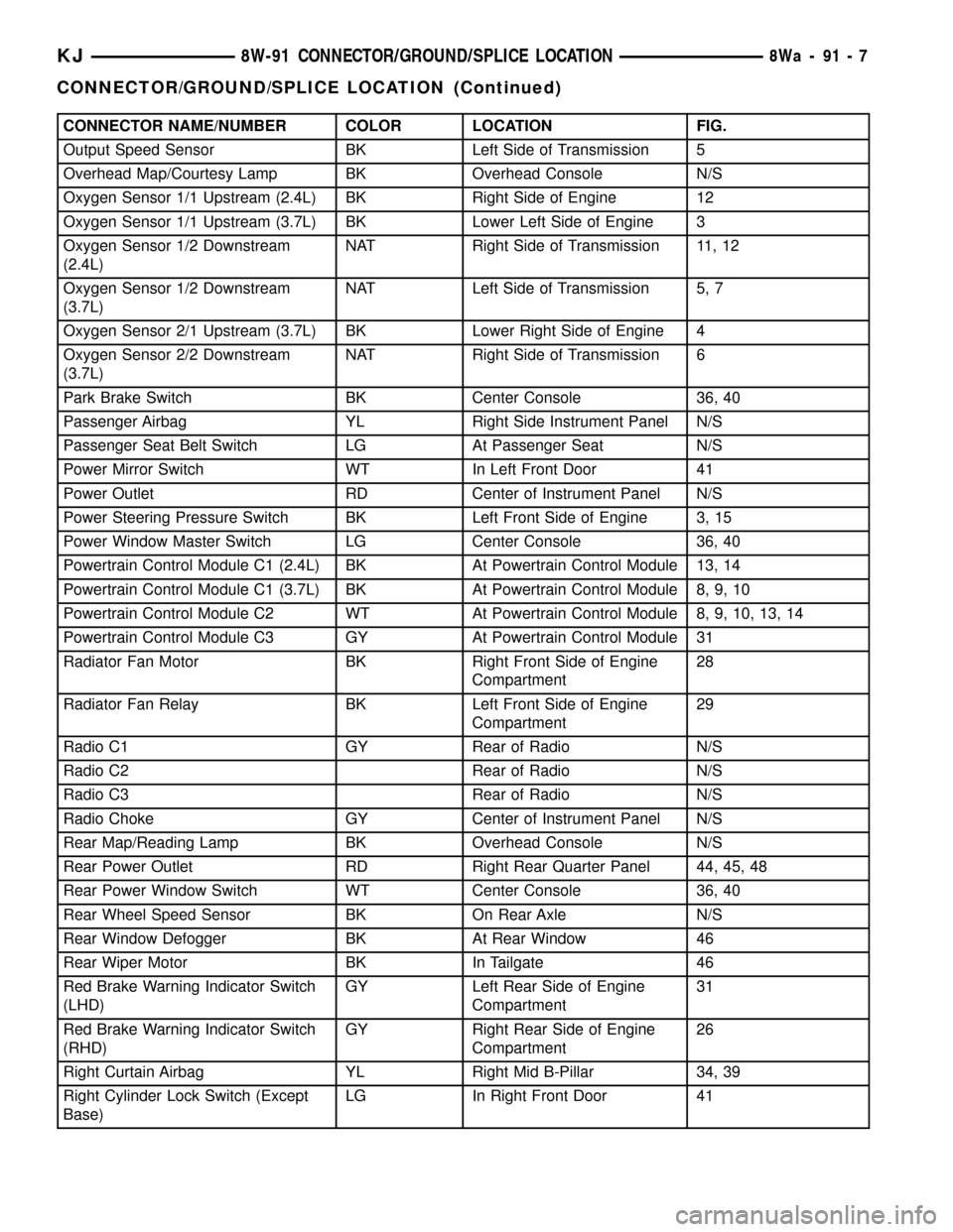
CONNECTOR NAME/NUMBER COLOR LOCATION FIG.
Output Speed Sensor BK Left Side of Transmission 5
Overhead Map/Courtesy Lamp BK Overhead Console N/S
Oxygen Sensor 1/1 Upstream (2.4L) BK Right Side of Engine 12
Oxygen Sensor 1/1 Upstream (3.7L) BK Lower Left Side of Engine 3
Oxygen Sensor 1/2 Downstream
(2.4L)NAT Right Side of Transmission 11, 12
Oxygen Sensor 1/2 Downstream
(3.7L)NAT Left Side of Transmission 5, 7
Oxygen Sensor 2/1 Upstream (3.7L) BK Lower Right Side of Engine 4
Oxygen Sensor 2/2 Downstream
(3.7L)NAT Right Side of Transmission 6
Park Brake Switch BK Center Console 36, 40
Passenger Airbag YL Right Side Instrument Panel N/S
Passenger Seat Belt Switch LG At Passenger Seat N/S
Power Mirror Switch WT In Left Front Door 41
Power Outlet RD Center of Instrument Panel N/S
Power Steering Pressure Switch BK Left Front Side of Engine 3, 15
Power Window Master Switch LG Center Console 36, 40
Powertrain Control Module C1 (2.4L) BK At Powertrain Control Module 13, 14
Powertrain Control Module C1 (3.7L) BK At Powertrain Control Module 8, 9, 10
Powertrain Control Module C2 WT At Powertrain Control Module 8, 9, 10, 13, 14
Powertrain Control Module C3 GY At Powertrain Control Module 31
Radiator Fan Motor BK Right Front Side of Engine
Compartment28
Radiator Fan Relay BK Left Front Side of Engine
Compartment29
Radio C1 GY Rear of Radio N/S
Radio C2 Rear of Radio N/S
Radio C3 Rear of Radio N/S
Radio Choke GY Center of Instrument Panel N/S
Rear Map/Reading Lamp BK Overhead Console N/S
Rear Power Outlet RD Right Rear Quarter Panel 44, 45, 48
Rear Power Window Switch WT Center Console 36, 40
Rear Wheel Speed Sensor BK On Rear Axle N/S
Rear Window Defogger BK At Rear Window 46
Rear Wiper Motor BK In Tailgate 46
Red Brake Warning Indicator Switch
(LHD)GY Left Rear Side of Engine
Compartment31
Red Brake Warning Indicator Switch
(RHD)GY Right Rear Side of Engine
Compartment26
Right Curtain Airbag YL Right Mid B-Pillar 34, 39
Right Cylinder Lock Switch (Except
Base)LG In Right Front Door 41
KJ8W-91 CONNECTOR/GROUND/SPLICE LOCATION8Wa-91-7
CONNECTOR/GROUND/SPLICE LOCATION (Continued)
Page 1166 of 1803
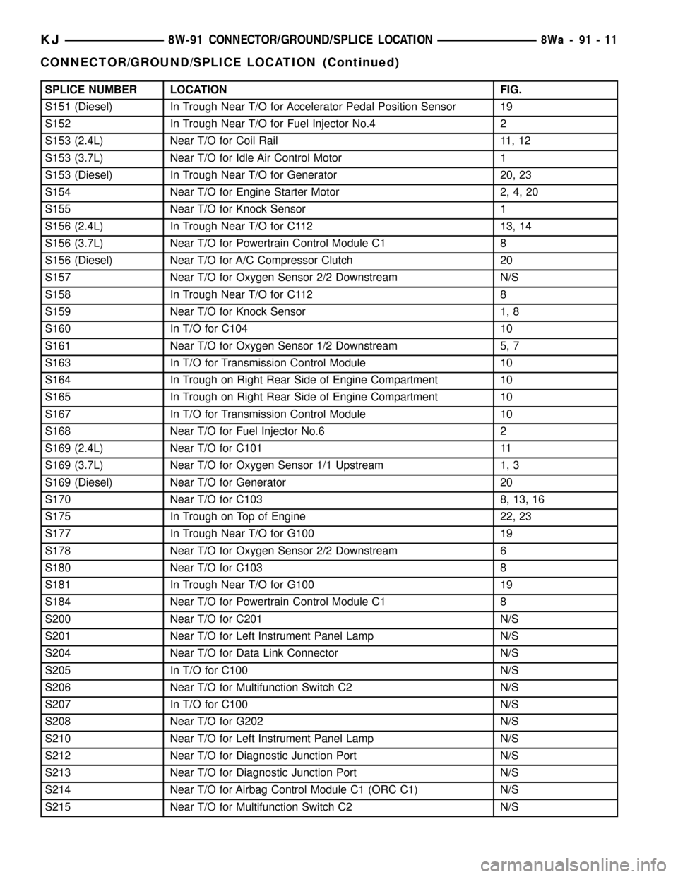
SPLICE NUMBER LOCATION FIG.
S151 (Diesel) In Trough Near T/O for Accelerator Pedal Position Sensor 19
S152 In Trough Near T/O for Fuel Injector No.4 2
S153 (2.4L) Near T/O for Coil Rail 11, 12
S153 (3.7L) Near T/O for Idle Air Control Motor 1
S153 (Diesel) In Trough Near T/O for Generator 20, 23
S154 Near T/O for Engine Starter Motor 2, 4, 20
S155 Near T/O for Knock Sensor 1
S156 (2.4L) In Trough Near T/O for C112 13, 14
S156 (3.7L) Near T/O for Powertrain Control Module C1 8
S156 (Diesel) Near T/O for A/C Compressor Clutch 20
S157 Near T/O for Oxygen Sensor 2/2 Downstream N/S
S158 In Trough Near T/O for C112 8
S159 Near T/O for Knock Sensor 1, 8
S160 In T/O for C104 10
S161 Near T/O for Oxygen Sensor 1/2 Downstream 5, 7
S163 In T/O for Transmission Control Module 10
S164 In Trough on Right Rear Side of Engine Compartment 10
S165 In Trough on Right Rear Side of Engine Compartment 10
S167 In T/O for Transmission Control Module 10
S168 Near T/O for Fuel Injector No.6 2
S169 (2.4L) Near T/O for C101 11
S169 (3.7L) Near T/O for Oxygen Sensor 1/1 Upstream 1, 3
S169 (Diesel) Near T/O for Generator 20
S170 Near T/O for C103 8, 13, 16
S175 In Trough on Top of Engine 22, 23
S177 In Trough Near T/O for G100 19
S178 Near T/O for Oxygen Sensor 2/2 Downstream 6
S180 Near T/O for C103 8
S181 In Trough Near T/O for G100 19
S184 Near T/O for Powertrain Control Module C1 8
S200 Near T/O for C201 N/S
S201 Near T/O for Left Instrument Panel Lamp N/S
S204 Near T/O for Data Link Connector N/S
S205 In T/O for C100 N/S
S206 Near T/O for Multifunction Switch C2 N/S
S207 In T/O for C100 N/S
S208 Near T/O for G202 N/S
S210 Near T/O for Left Instrument Panel Lamp N/S
S212 Near T/O for Diagnostic Junction Port N/S
S213 Near T/O for Diagnostic Junction Port N/S
S214 Near T/O for Airbag Control Module C1 (ORC C1) N/S
S215 Near T/O for Multifunction Switch C2 N/S
KJ8W-91 CONNECTOR/GROUND/SPLICE LOCATION8Wa-91-11
CONNECTOR/GROUND/SPLICE LOCATION (Continued)
Page 1341 of 1803
STRUCTURAL COLLAR
REMOVAL
(1) Raise vehicle on hoist.
(2) Remove structural collar attaching bolts.
(3) Remove collar.
INSTALLATION
CAUTION: Torque procedure for the structural collar
must be followed or damage could occur to oil pan
and collar.
(1) Perform the following steps for installing struc-
tural collar.
²Step 1: Position collar between transmission and
oil pan. Install collar to transmission bolts,hand
start only.
²Step 2: Install collar to oil pan bolts,hand snug
only.
²Step 3: Tighten collar to transmission bolts.
²Step 4: Tighten collar to oil pan bolts.
(2) Lower vehicle.
ENGINE MOUNTING
DESCRIPTION
The engine mounting system consist of three
mounts; right and a left side support the powertrain,
and rear mount to control powertrain torque. The
mounts are of molded rubber material.
FRONT MOUNT
REMOVAL
(1) Raise vehicle on hoist.
(2) Remove the front engine mount through bolt
from the insulator.
(3) Remove the engine front mount bolts and
remove the insulator assembly.
(4) Remove the front mounting bracket from
engine, if necessary.
INSTALLATION
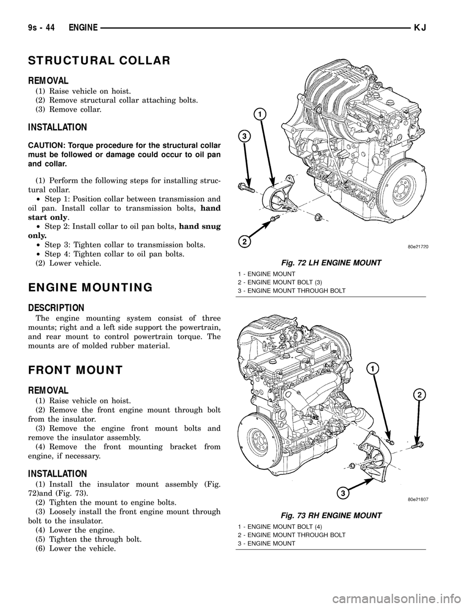
(1) Install the insulator mount assembly (Fig.
72)and (Fig. 73).
(2) Tighten the mount to engine bolts.
(3) Loosely install the front engine mount through
bolt to the insulator.
(4) Lower the engine.
(5) Tighten the through bolt.
(6) Lower the vehicle.
Fig. 72 LH ENGINE MOUNT
1 - ENGINE MOUNT
2 - ENGINE MOUNT BOLT (3)
3 - ENGINE MOUNT THROUGH BOLT
Fig. 73 RH ENGINE MOUNT
1 - ENGINE MOUNT BOLT (4)
2 - ENGINE MOUNT THROUGH BOLT
3 - ENGINE MOUNT
9s - 44 ENGINEKJ
Page 1391 of 1803

FUEL LEVEL SENDING UNIT /
SENSOR
DESCRIPTION
The fuel gauge sending unit (fuel level sensor) is
attached to the side of the fuel pump module. The
sending unit consists of a float, an arm, and a vari-
able resistor track (card).
OPERATION
The fuel pump module has 4 different circuits
(wires). Two of these circuits are used for the fuel
gauge sending unit for fuel gauge operation, and for
certain OBD II emission requirements. The other 2
wires are used for electric fuel pump operation.
For Fuel Gauge Operation:A constant current
source of approximately 32 milliamps is supplied to
the resistor track on the fuel gauge sending unit.
This is fed directly from the Powertrain Control Mod-
ule (PCM).NOTE: For diagnostic purposes, this
12V power source can only be verified with the
circuit opened (fuel pump module electrical
connector unplugged). With the connectors
plugged, output voltages will vary from about
0.6 volts at FULL, to about 8.6 volts at EMPTY
(about 8.6 volts at EMPTY for Jeep models, and
about 7.0 volts at EMPTY for Dodge Truck mod-
els).The resistor track is used to vary the voltage
(resistance) depending on fuel tank float level. As
fuel level increases, the float and arm move up,
which decreases voltage. As fuel level decreases, the
float and arm move down, which increases voltage.
The varied voltage signal is returned back to the
PCM through the sensor return circuit.
Both of the electrical circuits between the fuel
gauge sending unit and the PCM are hard-wired (not
multi-plexed). After the voltage signal is sent from
the resistor track, and back to the PCM, the PCM
will interpret the resistance (voltage) data and send
a message across the multi-plex bus circuits to the
instrument panel cluster. Here it is translated into
the appropriate fuel gauge level reading. Refer to
Instrument Panel for additional information.
For OBD II Emission Monitor Requirements:
The PCM will monitor the voltage output sent from
the resistor track on the sending unit to indicate fuel
level. The purpose of this feature is to prevent the
OBD II system from recording/setting false misfire
and fuel system monitor diagnostic trouble codes.
The feature is activated if the fuel level in the tank
is less than approximately 15 percent of its rated
capacity. If equipped with a Leak Detection Pump
(EVAP system monitor), this feature will also be acti-
vated if the fuel level in the tank is more than
approximately 85 percent of its rated capacity.
DIAGNOSIS AND TESTING - FUEL LEVEL
SENDING UNIT
The fuel level sending unit contains a variable
resistor (track). As the float moves up or down, elec-
trical resistance will change. Refer to Instrument
Panel and Gauges for Fuel Gauge testing. To test the
gauge sending unit only, it must be removed from
vehicle. The unit is a separate part of the lower fuel
pump module section. Refer to Fuel Pump Module
Removal/Installation for procedures (remove only the
upper section of the fuel pump module). Measure the
resistance across the sending unit terminals. With
float in up position, resistance should be 20 ohms (+/-
5%). With float in down position, resistance should be
270 ohms (+/- 5%).
REMOVAL
The fuel level sending unit (fuel level sensor) and
float assembly is located on the side of the lower sec-
tion of the fuel pump module. The lower section of
the fuel pump module is located within the fuel tank.
(1) Remove lower section of fuel pump module
from fuel tank. Refer to Fuel Pump Module Removal/
Installation.
(2) To remove sending unit from pump module, lift
on plastic locking tab (Fig. 8) while sliding sending
unit upwards.
(3) Disconnect 4±wire electrical connector (Fig. 9)
from bottom of upper section of fuel pump module.
Separate necessary sending unit wiring.
Fig. 8 FUEL LEVEL SENDING UNIT
1 - LIFT TAB HERE FOR REMOVAL
2 - FUEL LEVEL SENDING UNIT
3 - LOWER SECTION OF PUMP MODULE
KJFUEL DELIVERY 14 - 9
Page 1411 of 1803

FUEL INJECTION
TABLE OF CONTENTS
page page
FUEL INJECTION
DESCRIPTION.........................29
ACCELERATOR PEDAL
REMOVAL.............................29
INSTALLATION.........................30
CRANKSHAFT POSITION SENSOR
DESCRIPTION.........................30
OPERATION...........................31
REMOVAL.............................31
INSTALLATION.........................32
FUEL INJECTOR
DESCRIPTION.........................33
OPERATION
OPERATION - FUEL INJECTOR..........33
OPERATION - PCM OUTPUT............33
DIAGNOSIS AND TESTING - FUEL INJECTOR . 33
REMOVAL.............................34
INSTALLATION.........................34
FUEL PUMP RELAY
DESCRIPTION.........................34
OPERATION...........................34
DIAGNOSIS AND TESTING - FUEL PUMP
RELAY..............................34
REMOVAL.............................34
INSTALLATION.........................34
IDLE AIR CONTROL MOTOR
DESCRIPTION.........................35
OPERATION...........................35
REMOVAL.............................36INSTALLATION.........................36
INTAKE AIR TEMPERATURE SENSOR
DESCRIPTION.........................36
OPERATION...........................36
REMOVAL.............................37
INSTALLATION.........................38
MAP SENSOR
DESCRIPTION.........................38
OPERATION...........................38
REMOVAL.............................39
INSTALLATION.........................40
OXYGEN SENSOR
DESCRIPTION.........................40
OPERATION...........................40
REMOVAL.............................41
INSTALLATION.........................43
THROTTLE BODY
DESCRIPTION.........................43
OPERATION...........................43
REMOVAL.............................43
INSTALLATION.........................44
THROTTLE CONTROL CABLE
REMOVAL.............................45
INSTALLATION.........................46
THROTTLE POSITION SENSOR
DESCRIPTION.........................47
OPERATION...........................47
REMOVAL.............................47
INSTALLATION.........................48
FUEL INJECTION
DESCRIPTION
The Powertrain Control Module (PCM) operates
the fuel injection system. Refer to Powertrain Control
Module in Electronic Control Modules for informa-
tion.
ACCELERATOR PEDAL
REMOVAL
The accelerator pedal is serviced as a complete
assembly including the bracket.The accelerator pedal is connected to the upper
part of the accelerator pedal arm by a plastic
retainer (clip) (Fig. 1). This plastic retainer snaps
into the top of the accelerator pedal arm.
(1) From inside the vehicle, hold up accelerator
pedal. Remove plastic cable retainer (clip) and throt-
tle cable core wire from upper end of accelerator
pedal arm (Fig. 1). Plastic cable retainer (clip) snaps
into pedal arm.
(2) Remove 2 accelerator pedal mounting bracket
nuts. Remove accelerator pedal assembly.
KJFUEL INJECTION 14 - 29
Page 1413 of 1803
OPERATION
2.4L
Engine speed and crankshaft position are provided
through the CKP (Crankshaft Position) sensor. The
sensor generates pulses that are the input sent to the
Powertrain Control Module (PCM). The PCM inter-
prets the sensor input to determine the crankshaft
position. The PCM then uses this position, along with
other inputs, to determine injector sequence and igni-
tion timing.
The sensor is a hall effect device combined with an
internal magnet. It is also sensitive to steel within a
certain distance from it.
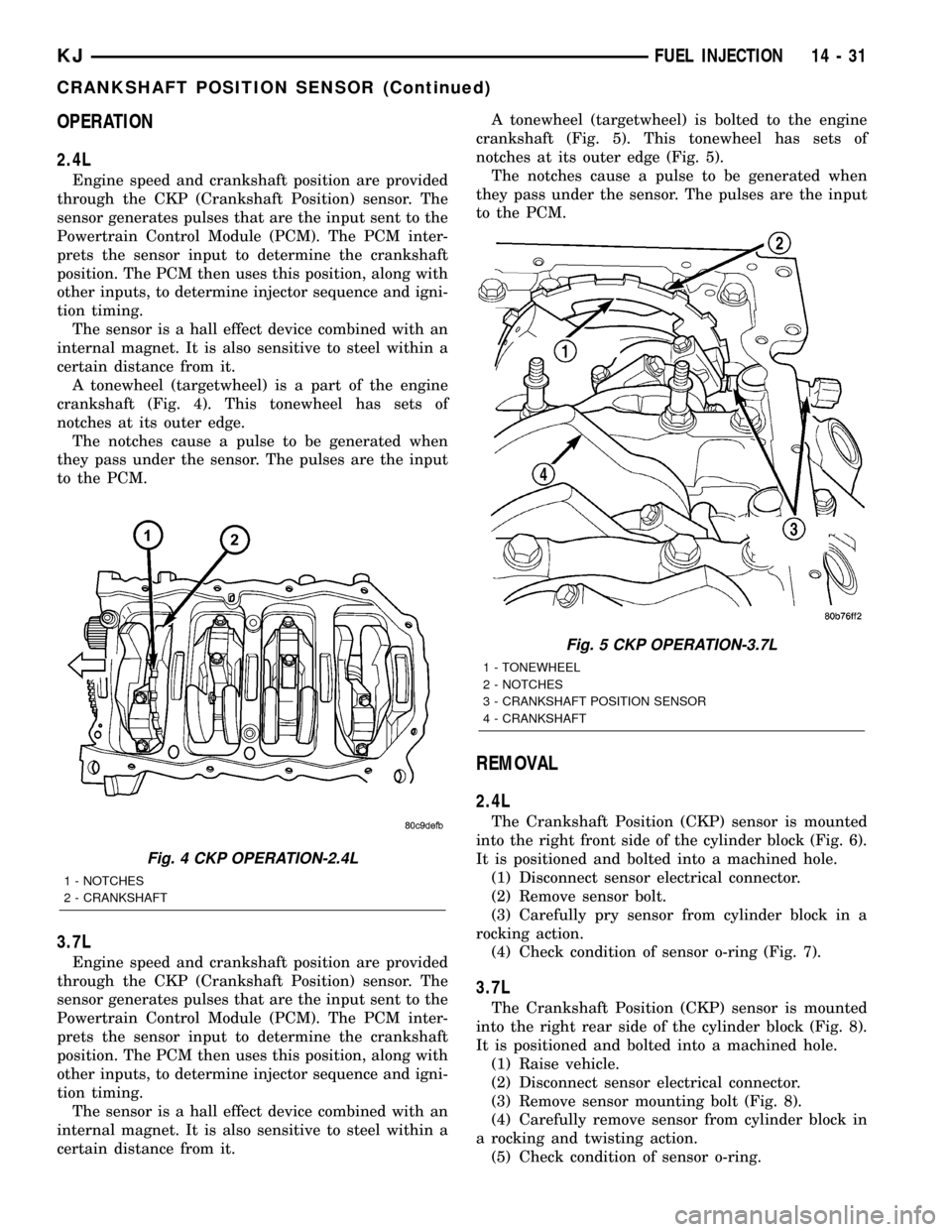
A tonewheel (targetwheel) is a part of the engine
crankshaft (Fig. 4). This tonewheel has sets of
notches at its outer edge.
The notches cause a pulse to be generated when
they pass under the sensor. The pulses are the input
to the PCM.
3.7L
Engine speed and crankshaft position are provided
through the CKP (Crankshaft Position) sensor. The
sensor generates pulses that are the input sent to the
Powertrain Control Module (PCM). The PCM inter-
prets the sensor input to determine the crankshaft
position. The PCM then uses this position, along with
other inputs, to determine injector sequence and igni-
tion timing.
The sensor is a hall effect device combined with an
internal magnet. It is also sensitive to steel within a
certain distance from it.A tonewheel (targetwheel) is bolted to the engine
crankshaft (Fig. 5). This tonewheel has sets of
notches at its outer edge (Fig. 5).
The notches cause a pulse to be generated when
they pass under the sensor. The pulses are the input
to the PCM.
REMOVAL
2.4L
The Crankshaft Position (CKP) sensor is mounted
into the right front side of the cylinder block (Fig. 6).
It is positioned and bolted into a machined hole.
(1) Disconnect sensor electrical connector.
(2) Remove sensor bolt.
(3) Carefully pry sensor from cylinder block in a
rocking action.
(4) Check condition of sensor o-ring (Fig. 7).
3.7L
The Crankshaft Position (CKP) sensor is mounted
into the right rear side of the cylinder block (Fig. 8).
It is positioned and bolted into a machined hole.
(1) Raise vehicle.
(2) Disconnect sensor electrical connector.
(3) Remove sensor mounting bolt (Fig. 8).
(4) Carefully remove sensor from cylinder block in
a rocking and twisting action.
(5) Check condition of sensor o-ring.
Fig. 4 CKP OPERATION-2.4L
1 - NOTCHES
2 - CRANKSHAFT
Fig. 5 CKP OPERATION-3.7L
1 - TONEWHEEL
2 - NOTCHES
3 - CRANKSHAFT POSITION SENSOR
4 - CRANKSHAFT
KJFUEL INJECTION 14 - 31
CRANKSHAFT POSITION SENSOR (Continued)
Page 1415 of 1803

FUEL INJECTOR
DESCRIPTION
An individual fuel injector (Fig. 9) is used for each
individual cylinder.
OPERATION
OPERATION - FUEL INJECTOR
The top (fuel entry) end of the injector (Fig. 9) is
attached into an opening on the fuel rail.
The fuel injectors are electrical solenoids. The
injector contains a pintle that closes off an orifice at
the nozzle end. When electric current is supplied to
the injector, the armature and needle move a short
distance against a spring, allowing fuel to flow out
the orifice. Because the fuel is under high pressure, a
fine spray is developed in the shape of a pencil
stream. The spraying action atomizes the fuel, add-
ing it to the air entering the combustion chamber.
The nozzle (outlet) ends of the injectors are posi-
tioned into openings in the intake manifold just
above the intake valve ports of the cylinder head.
The engine wiring harness connector for each fuel
injector is equipped with an attached numerical tag
(INJ 1, INJ 2 etc.). This is used to identify each fuel
injector.
The injectors are energized individually in a
sequential order by the Powertrain Control Module(PCM). The PCM will adjust injector pulse width by
switching the ground path to each individual injector
on and off. Injector pulse width is the period of time
that the injector is energized. The PCM will adjust
injector pulse width based on various inputs it
receives.
Battery voltage is supplied to the injectors through
the ASD relay.
The PCM determines injector pulse width based on
various inputs.
OPERATION - PCM OUTPUT
The nozzle ends of the injectors are positioned into
openings in the intake manifold just above the intake
valve ports of the cylinder head. The engine wiring
harness connector for each fuel injector is equipped
with an attached numerical tag (INJ 1, INJ 2 etc.).
This is used to identify each fuel injector with its
respective cylinder number.
The injectors are energized individually in a
sequential order by the Powertrain Control Module
(PCM). The PCM will adjust injector pulse width by
switching the ground path to each individual injector
on and off. Injector pulse width is the period of time
that the injector is energized. The PCM will adjust
injector pulse width based on various inputs it
receives.
Battery voltage (12 volts +) is supplied to the injec-
tors through the ASD relay. The ASD relay will shut-
down the 12 volt power source to the fuel injectors if
the PCM senses the ignition is on, but the engine is
not running. This occurs after the engine has not
been running for approximately 1.8 seconds.
The PCM determines injector on-time (pulse width)
based on various inputs.
DIAGNOSIS AND TESTING - FUEL INJECTOR
To perform a complete test of the fuel injectors and
their circuitry, use the DRB scan tool and refer to the
appropriate Powertrain Diagnostics Procedures man-
ual. To test the injector only, refer to the following:
Disconnect the fuel injector wire harness connector
from the injector. The injector is equipped with 2
electrical terminals (pins). Place an ohmmeter across
the terminals. Resistance reading should be approxi-
mately 12 ohms 1.2 ohms at 20ÉC (68ÉF).
Fig. 9 FUEL INJECTOR Ð TYPICAL
KJFUEL INJECTION 14 - 33
Page 1416 of 1803
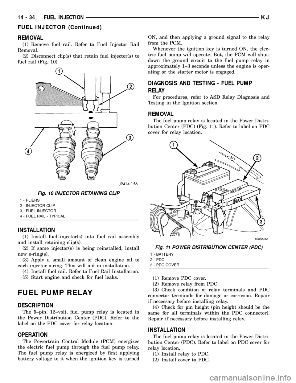
REMOVAL
(1) Remove fuel rail. Refer to Fuel Injector Rail
Removal.
(2) Disconnect clip(s) that retain fuel injector(s) to
fuel rail (Fig. 10).
INSTALLATION
(1) Install fuel injector(s) into fuel rail assembly
and install retaining clip(s).
(2) If same injector(s) is being reinstalled, install
new o-ring(s).
(3) Apply a small amount of clean engine oil to
each injector o-ring. This will aid in installation.
(4) Install fuel rail. Refer to Fuel Rail Installation.
(5) Start engine and check for fuel leaks.
FUEL PUMP RELAY
DESCRIPTION
The 5±pin, 12±volt, fuel pump relay is located in
the Power Distribution Center (PDC). Refer to the
label on the PDC cover for relay location.
OPERATION
The Powertrain Control Module (PCM) energizes
the electric fuel pump through the fuel pump relay.
The fuel pump relay is energized by first applying
battery voltage to it when the ignition key is turnedON, and then applying a ground signal to the relay
from the PCM.
Whenever the ignition key is turned ON, the elec-
tric fuel pump will operate. But, the PCM will shut-
down the ground circuit to the fuel pump relay in
approximately 1±3 seconds unless the engine is oper-
ating or the starter motor is engaged.
DIAGNOSIS AND TESTING - FUEL PUMP
RELAY
For procedures, refer to ASD Relay Diagnosis and
Testing in the Ignition section.
REMOVAL
The fuel pump relay is located in the Power Distri-
bution Center (PDC) (Fig. 11). Refer to label on PDC
cover for relay location.
(1) Remove PDC cover.
(2) Remove relay from PDC.
(3) Check condition of relay terminals and PDC
connector terminals for damage or corrosion. Repair
if necessary before installing relay.
(4) Check for pin height (pin height should be the
same for all terminals within the PDC connector).
Repair if necessary before installing relay.
INSTALLATION
The fuel pump relay is located in the Power Distri-
bution Center (PDC). Refer to label on PDC cover for
relay location.
(1) Install relay to PDC.
(2) Install cover to PDC.
Fig. 10 INJECTOR RETAINING CLIP
1 - PLIERS
2 - INJECTOR CLIP
3 - FUEL INJECTOR
4 - FUEL RAIL - TYPICAL
Fig. 11 POWER DISTRIBUTION CENTER (PDC)
1 - BATTERY
2 - PDC
3 - PDC COVER
14 - 34 FUEL INJECTIONKJ
FUEL INJECTOR (Continued)