2002 JEEP LIBERTY Speed control system
[x] Cancel search: Speed control systemPage 898 of 1803

8W-31 TRANSMISSION CONTROL SYSTEM
Component Page
A/C Compressor Clutch Relay.......... 8Wa-31-3
Auto Shut Down Relay............... 8Wa-31-3
Back-Up Lamp Switch............... 8Wa-31-4
Brake Lamp Switch................. 8Wa-31-5
Crankshaft Position Sensor............ 8Wa-31-6
Data Link Connector................. 8Wa-31-6
Diagnostic Junction Port.............. 8Wa-31-3
Engine Control Module............... 8Wa-31-6
Fuel Pump Relay................... 8Wa-31-3
Fuse 5............................ 8Wa-31-2
Fuse 15........................... 8Wa-31-3
Fuse 28........................... 8Wa-31-3
Fuse 38........................... 8Wa-31-5
Fuse 39........................... 8Wa-31-4
G102........................... 8Wa-31-7, 9
G111 ............................. 8Wa-31-2
G301............................. 8Wa-31-5
Input Speed Sensor.................. 8Wa-31-9Component Page
Instrument Cluster.................. 8Wa-31-5
Junction Block.................. 8Wa-31-3, 4, 5
Left Tail/Stop Lamp................. 8Wa-31-4
Line Pressure Sensor................ 8Wa-31-9
Output Speed Sensor................ 8Wa-31-9
Power Distribution Center.......... 8Wa-31-2, 3
Powertrain Control Module........ 8Wa-31-3, 5, 6
Right Tail/Stop Lamp................ 8Wa-31-4
Shifter Assembly.................... 8Wa-31-5
Starter Motor Relay................. 8Wa-31-8
Throttle Position Sensor.............. 8Wa-31-5
Trailer Tow Connector................ 8Wa-31-4
Transfer Case Position Sensor.......... 8Wa-31-5
Transmission Control Module . . 8Wa-31-2, 3, 5, 6, 7,
8, 9
Transmission Control Relay....... 8Wa-31-2, 7, 8
Transmission Solenoid/Trs Assembly . . 8Wa-31-2, 4,
7, 8, 9
KJ8W-31 TRANSMISSION CONTROL SYSTEM8Wa-31-1
Page 1220 of 1803
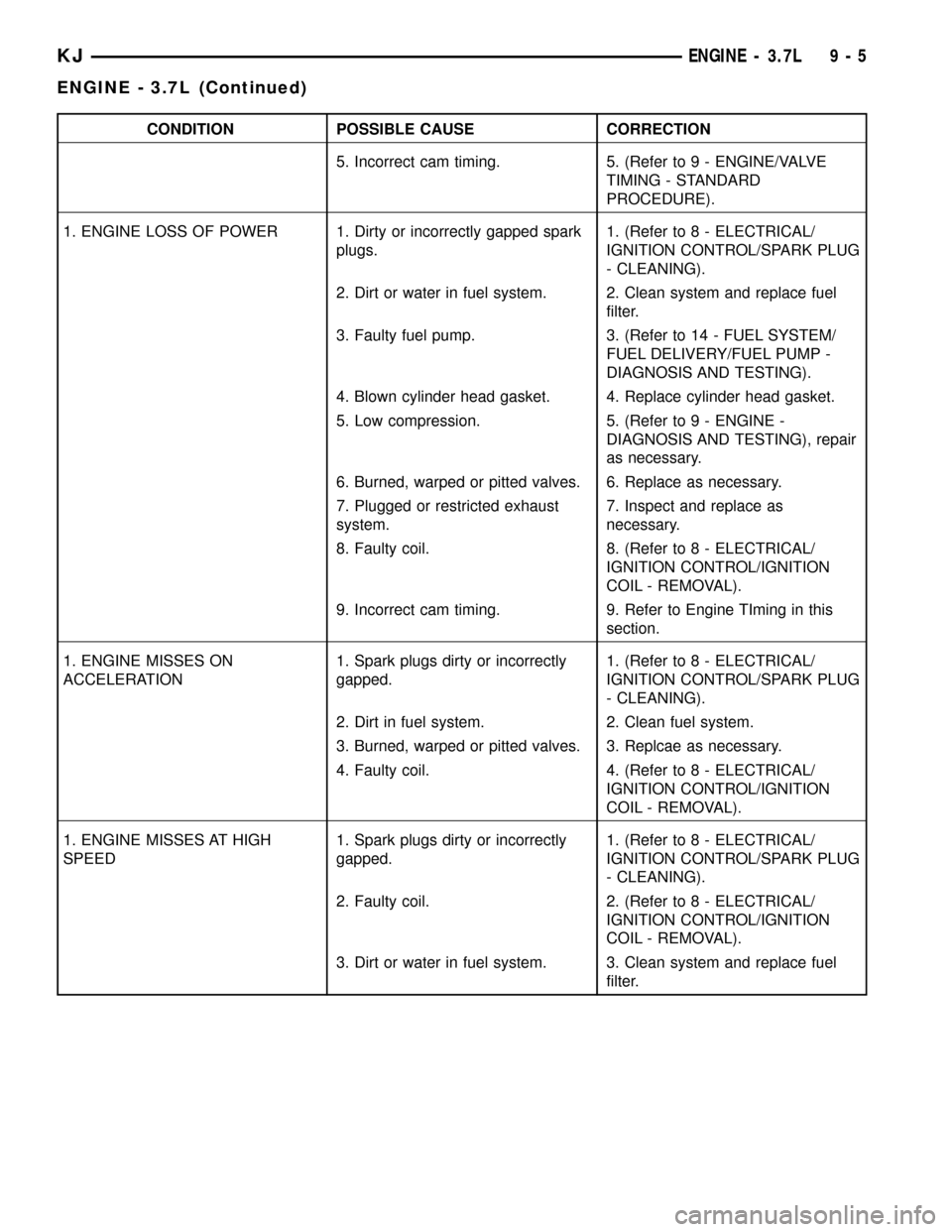
CONDITION POSSIBLE CAUSE CORRECTION
5. Incorrect cam timing. 5. (Refer to 9 - ENGINE/VALVE
TIMING - STANDARD
PROCEDURE).
1. ENGINE LOSS OF POWER 1. Dirty or incorrectly gapped spark
plugs.1. (Refer to 8 - ELECTRICAL/
IGNITION CONTROL/SPARK PLUG
- CLEANING).
2. Dirt or water in fuel system. 2. Clean system and replace fuel
filter.
3. Faulty fuel pump. 3. (Refer to 14 - FUEL SYSTEM/
FUEL DELIVERY/FUEL PUMP -
DIAGNOSIS AND TESTING).
4. Blown cylinder head gasket. 4. Replace cylinder head gasket.
5. Low compression. 5. (Refer to 9 - ENGINE -
DIAGNOSIS AND TESTING), repair
as necessary.
6. Burned, warped or pitted valves. 6. Replace as necessary.
7. Plugged or restricted exhaust
system.7. Inspect and replace as
necessary.
8. Faulty coil. 8. (Refer to 8 - ELECTRICAL/
IGNITION CONTROL/IGNITION
COIL - REMOVAL).
9. Incorrect cam timing. 9. Refer to Engine TIming in this
section.
1. ENGINE MISSES ON
ACCELERATION1. Spark plugs dirty or incorrectly
gapped.1. (Refer to 8 - ELECTRICAL/
IGNITION CONTROL/SPARK PLUG
- CLEANING).
2. Dirt in fuel system. 2. Clean fuel system.
3. Burned, warped or pitted valves. 3. Replcae as necessary.
4. Faulty coil. 4. (Refer to 8 - ELECTRICAL/
IGNITION CONTROL/IGNITION
COIL - REMOVAL).
1. ENGINE MISSES AT HIGH
SPEED1. Spark plugs dirty or incorrectly
gapped.1. (Refer to 8 - ELECTRICAL/
IGNITION CONTROL/SPARK PLUG
- CLEANING).
2. Faulty coil. 2. (Refer to 8 - ELECTRICAL/
IGNITION CONTROL/IGNITION
COIL - REMOVAL).
3. Dirt or water in fuel system. 3. Clean system and replace fuel
filter.
KJENGINE - 3.7L 9 - 5
ENGINE - 3.7L (Continued)
Page 1225 of 1803
²Tapping the hole with a special Heli-Coil Tap, or
equivalent.
²Installing an insert into the tapped hole to bring
the hole back to its original thread size.
STANDARD PROCEDURE - ENGINE CORE AND
OIL GALLERY PLUGS
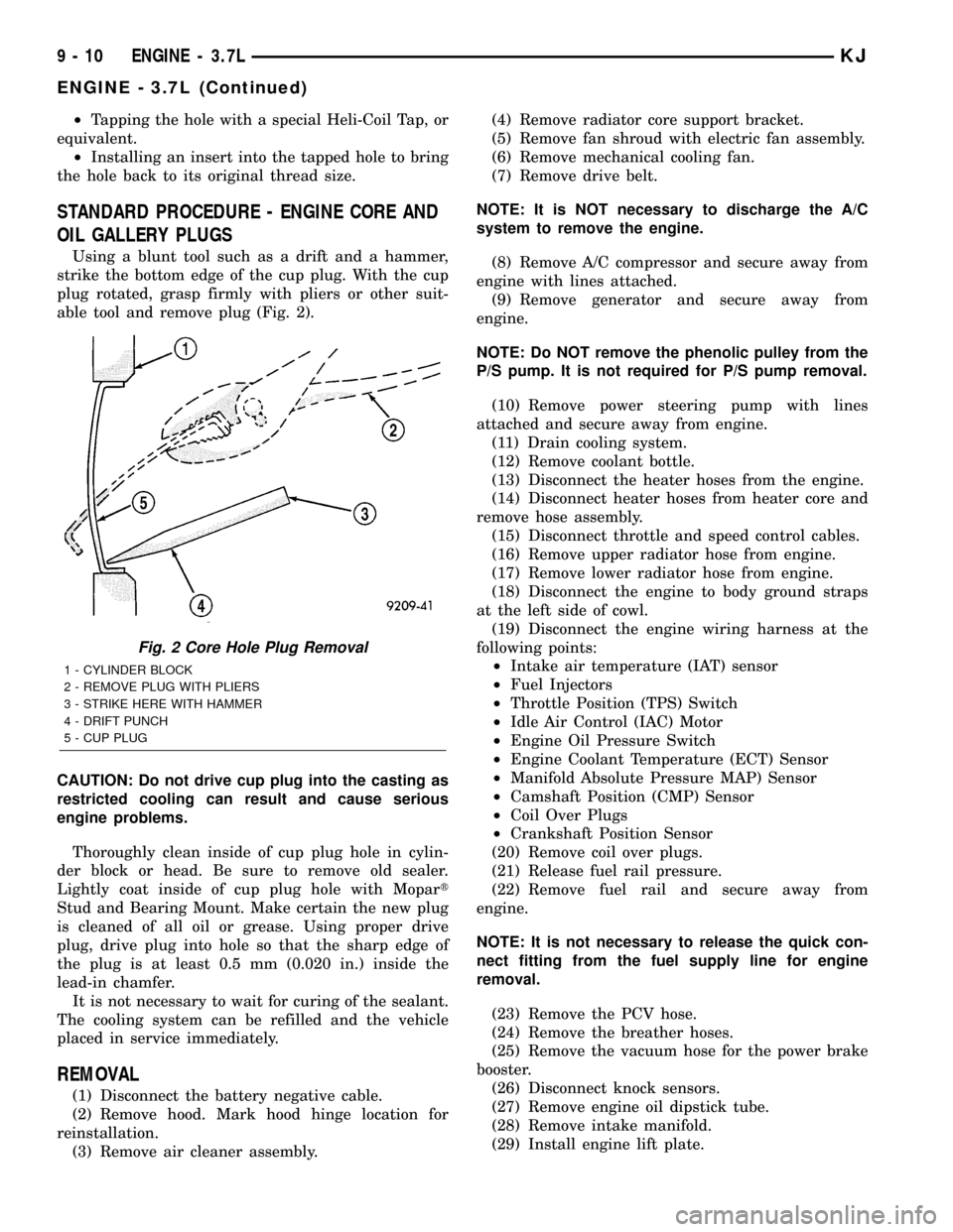
Using a blunt tool such as a drift and a hammer,
strike the bottom edge of the cup plug. With the cup
plug rotated, grasp firmly with pliers or other suit-
able tool and remove plug (Fig. 2).
CAUTION: Do not drive cup plug into the casting as
restricted cooling can result and cause serious
engine problems.
Thoroughly clean inside of cup plug hole in cylin-
der block or head. Be sure to remove old sealer.
Lightly coat inside of cup plug hole with Mopart
Stud and Bearing Mount. Make certain the new plug
is cleaned of all oil or grease. Using proper drive
plug, drive plug into hole so that the sharp edge of
the plug is at least 0.5 mm (0.020 in.) inside the
lead-in chamfer.
It is not necessary to wait for curing of the sealant.
The cooling system can be refilled and the vehicle
placed in service immediately.
REMOVAL
(1) Disconnect the battery negative cable.
(2) Remove hood. Mark hood hinge location for
reinstallation.
(3) Remove air cleaner assembly.(4) Remove radiator core support bracket.
(5) Remove fan shroud with electric fan assembly.
(6) Remove mechanical cooling fan.
(7) Remove drive belt.
NOTE: It is NOT necessary to discharge the A/C
system to remove the engine.
(8) Remove A/C compressor and secure away from
engine with lines attached.
(9) Remove generator and secure away from
engine.
NOTE: Do NOT remove the phenolic pulley from the
P/S pump. It is not required for P/S pump removal.
(10) Remove power steering pump with lines
attached and secure away from engine.
(11) Drain cooling system.
(12) Remove coolant bottle.
(13) Disconnect the heater hoses from the engine.
(14) Disconnect heater hoses from heater core and
remove hose assembly.
(15) Disconnect throttle and speed control cables.
(16) Remove upper radiator hose from engine.
(17) Remove lower radiator hose from engine.
(18) Disconnect the engine to body ground straps
at the left side of cowl.
(19) Disconnect the engine wiring harness at the
following points:
²Intake air temperature (IAT) sensor
²Fuel Injectors
²Throttle Position (TPS) Switch
²Idle Air Control (IAC) Motor
²Engine Oil Pressure Switch
²Engine Coolant Temperature (ECT) Sensor
²Manifold Absolute Pressure MAP) Sensor
²Camshaft Position (CMP) Sensor
²Coil Over Plugs
²Crankshaft Position Sensor
(20) Remove coil over plugs.
(21) Release fuel rail pressure.
(22) Remove fuel rail and secure away from
engine.
NOTE: It is not necessary to release the quick con-
nect fitting from the fuel supply line for engine
removal.
(23) Remove the PCV hose.
(24) Remove the breather hoses.
(25) Remove the vacuum hose for the power brake
booster.
(26) Disconnect knock sensors.
(27) Remove engine oil dipstick tube.
(28) Remove intake manifold.
(29) Install engine lift plate.
Fig. 2 Core Hole Plug Removal
1 - CYLINDER BLOCK
2 - REMOVE PLUG WITH PLIERS
3 - STRIKE HERE WITH HAMMER
4 - DRIFT PUNCH
5 - CUP PLUG
9 - 10 ENGINE - 3.7LKJ
ENGINE - 3.7L (Continued)
Page 1283 of 1803
INTAKE MANIFOLD
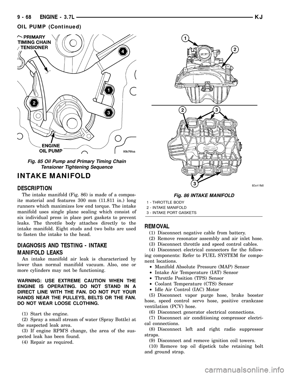
DESCRIPTION
The intake manifold (Fig. 86) is made of a compos-
ite material and features 300 mm (11.811 in.) long
runners which maximizes low end torque. The intake
manifold uses single plane sealing which consist of
six individual press in place port gaskets to prevent
leaks. The throttle body attaches directly to the
intake manifold. Eight studs and two bolts are used
to fasten the intake to the head.
DIAGNOSIS AND TESTING - INTAKE
MANIFOLD LEAKS
An intake manifold air leak is characterized by
lower than normal manifold vacuum. Also, one or
more cylinders may not be functioning.
WARNING: USE EXTREME CAUTION WHEN THE
ENGINE IS OPERATING. DO NOT STAND IN A
DIRECT LINE WITH THE FAN. DO NOT PUT YOUR
HANDS NEAR THE PULLEYS, BELTS OR THE FAN.
DO NOT WEAR LOOSE CLOTHING.
(1) Start the engine.
(2) Spray a small stream of water (Spray Bottle) at
the suspected leak area.
(3) If engine RPM'S change, the area of the sus-
pected leak has been found.
(4) Repair as required.
REMOVAL
(1) Disconnect negative cable from battery.
(2) Remove resonator assembly and air inlet hose.
(3) Disconnect throttle and speed control cables.
(4) Disconnect electrical connectors for the follow-
ing components: Refer to FUEL SYSTEM for compo-
nent locations.
²Manifold Absolute Pressure (MAP) Sensor
²Intake Air Temperature (IAT) Sensor
²Throttle Position (TPS) Sensor
²Coolant Temperature (CTS) Sensor
²Idle Air Control (IAC) Motor
(5) Disconnect vapor purge hose, brake booster
hose, speed control servo hose, positive crankcase
ventilation (PCV) hose.
(6) Disconnect generator electrical connections.
(7) Disconnect air conditioning compressor electri-
cal connections.
(8) Disconnect left and right radio suppressor
straps.
(9) Disconnect and remove ignition coil towers.
(10) Remove top oil dipstick tube retaining bolt
and ground strap.
Fig. 85 Oil Pump and Primary Timing Chain
Tensioner Tightening Sequence
Fig. 86 INTAKE MANIFOLD
1 - THROTTLE BODY
2 - INTAKE MANIFOLD
3 - INTAKE PORT GASKETS
9 - 68 ENGINE - 3.7LKJ
OIL PUMP (Continued)
Page 1284 of 1803
(11) Bleed fuel system. Refer to FUEL SYSTEM.
(12) Remove fuel rail.
(13) Remove throttle body assembly and mounting
bracket.
(14) Drain cooling system below coolant tempera-
ture level. Refer to COOLING SYSTEM.
(15) Remove the heater hoses from the engine
front cover and the heater core.
(16) Unclip and remove heater hoses and tubes
from intake manifold.
(17) Remove coolant temperature sensor. Refer to
FUEL SYSTEM.
(18) Remove intake manifold retaining fasteners in
reverse order of tightening sequence.
(19) Remove intake manifold.
INSTALLATION
(1) Install intake manifold gaskets.
(2) Install intake manifold.
(3) Install intake manifold retaining bolts and
tighten in sequence shown in to 12 N´m (105 in. lbs.).
(4) Install left and right radio suppressor straps.
(5) Install throttle body assembly.
(6) Install throttle cable bracket.
(7) Connect throttle cable and speed control cable
to throttle body.
(8) Install fuel rail.
(9) Install ignition coil towers.
(10) Position and install heater hoses and tubes
onto intake manifold.
(11) Install the heater hoses to the heater core and
engine front cover.
(12) Connect electrical connectors for the following
components:
²Manifold Absolute Pressure (MAP) Sensor
²Intake Air Temperature (IAT) Sensor
²Throttle Position (TPS) Sensor
²Coolant Temperature (CTS) Sensor
²Idle Air Control (IAC) Motor
²Ignition coil towers
²Fuel injectors
(13) Install top oil dipstick tube retaining bolt and
ground strap.
(14) Connect generator electrical connections.
(15) Connect Vapor purge hose, Brake booster
hose, Speed control servo hose, Positive crankcase
ventilation (PCV) hose.
(16) Fill cooling system.
(17) Install resonator assembly and air inlet hose.
(18) Connect negative cable to battery.
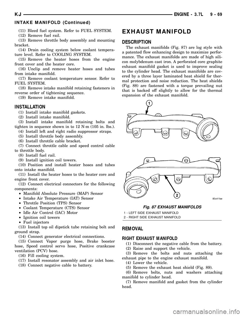
EXHAUST MANIFOLD
DESCRIPTION
The exhaust manifolds (Fig. 87) are log style with
a patented flow enhancing design to maximize perfor-
mance. The exhaust manifolds are made of high sili-
con molybdenum cast iron. A perforated core graphite
exhaust manifold gasket is used to improve sealing
to the cylinder head. The exhaust manifolds are cov-
ered by a three layer laminated heat shield for ther-
mal protection and noise reduction. The heat shields
(Fig. 88) are fastened with a torque prevailing nut
that is backed off slightly to allow for the thermal
expansion of the exhaust manifold.
REMOVAL
RIGHT EXHAUST MANIFOLD
(1) Disconnect the negative cable from the battery.
(2) Raise and support the vehicle.
(3) Remove the bolts and nuts attaching the
exhaust pipe to the engine exhaust manifold.
(4) Lower the vehicle.
(5) Remove the exhaust heat shield (Fig. 89).
(6) Remove bolts, nuts and washers attaching
manifold to cylinder head.
(7) Remove manifold and gasket from the cylinder
head.
Fig. 87 EXHAUST MANIFOLDS
1 - LEFT SIDE EXHAUST MANIFOLD
2 - RIGHT SIDE EXHAUST MANIFOLD
KJENGINE - 3.7L 9 - 69
INTAKE MANIFOLD (Continued)
Page 1286 of 1803
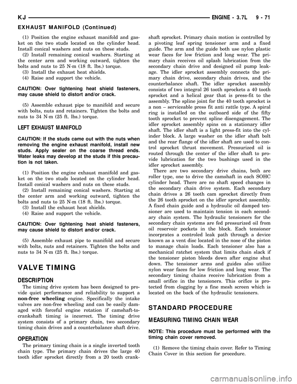
(1) Position the engine exhaust manifold and gas-
ket on the two studs located on the cylinder head.
Install conical washers and nuts on these studs.
(2) Install remaining conical washers. Starting at
the center arm and working outward, tighten the
bolts and nuts to 25 N´m (18 ft. lbs.) torque.
(3) Install the exhaust heat shields.
(4) Raise and support the vehicle.
CAUTION: Over tightening heat shield fasteners,
may cause shield to distort and/or crack.
(5) Assemble exhaust pipe to manifold and secure
with bolts, nuts and retainers. Tighten the bolts and
nuts to 34 N´m (25 ft. lbs.) torque.
LEFT EXHAUST MANIFOLD
CAUTION: If the studs came out with the nuts when
removing the engine exhaust manifold, install new
studs. Apply sealer on the coarse thread ends.
Water leaks may develop at the studs if this precau-
tion is not taken.
(1) Position the engine exhaust manifold and gas-
ket on the two studs located on the cylinder head.
Install conical washers and nuts on these studs.
(2) Install remaining conical washers. Starting at
the center arm and working outward, tighten the
bolts and nuts to 25 N´m (18 ft. lbs.) torque.
(3) Install the exhaust heat shields.
(4) Raise and support the vehicle.
CAUTION: Over tightening heat shield fasteners,
may cause shield to distort and/or crack.
(5) Assemble exhaust pipe to manifold and secure
with bolts, nuts and retainers. Tighten the bolts and
nuts to 34 N´m (25 ft. lbs.) torque.
VALVE TIMING
DESCRIPTION
The timing drive system has been designed to pro-
vide quiet performance and reliability to support a
non-free wheelingengine. Specifically the intake
valves are non-free wheeling and can be easily dam-
aged with forceful engine rotation if camshaft-to-
crankshaft timing is incorrect. The timing drive
system consists of a primary chain, two secondary
timing chain drives and a counterbalance shaft drive.
OPERATION
The primary timing chain is a single inverted tooth
chain type. The primary chain drives the large 40
tooth idler sprocket directly from a 20 tooth crank-shaft sprocket. Primary chain motion is controlled by
a pivoting leaf spring tensioner arm and a fixed
guide. The arm and the guide both use nylon plastic
wear faces for low friction and long wear. The pri-
mary chain receives oil splash lubrication from the
secondary chain drive and designed oil pump leak-
age. The idler sprocket assembly connects the pri-
mary chain drive, secondary chain drives, and the
counterbalance shaft. The idler sprocket assembly
consists of two integral 26 tooth sprockets a 40 tooth
sprocket and a helical gear that is press-fit to the
assembly. The spline joint for the 40 tooth sprocket is
a non ± serviceable press fit anti rattle type. A spiral
ring is installed on the outboard side of the fifty
tooth sprocket to prevent spline disengagement. The
idler sprocket assembly spins on a stationary idler
shaft. The idler shaft is a light press-fit into the cyl-
inder block. A large washer on the idler shaft bolt
and the rear flange of the idler shaft are used to con-
trol sprocket thrust movement. Pressurized oil is
routed through the center of the idler shaft to pro-
vide lubrication for the two bushings used in the
idler sprocket assembly.
There are two secondary drive chains, both are
roller type, one to drive the camshaft in each SOHC
cylinder head. There are no shaft speed changes in
the secondary chain drive system. Each secondary
chain drives a 26 tooth cam sprocket directly from
the 26 tooth sprocket on the idler sprocket assembly.
A fixed chain guide and a hydraulic oil damped ten-
sioner are used to maintain tension in each second-
ary chain system. The hydraulic tensioners for the
secondary chain systems are fed pressurized oil from
oil reservoir pockets in the block. Each tensioner
incorprates a controled leak path through a device
known as a vent disc located in the nose of the piston
to manage chain loads. Each tensioner also has a
mechanical ratchet system that limits chain slack if
the tensioner piston bleeds down after engine shut
down. The tensioner arms and guides also utilize
nylon wear faces for low friction and long wear. The
secondary timing chains receive lubrication from a
small orifice in the tensioners. This orifice is pro-
tected from clogging by a fine mesh screen which is
located on the back of the hydraulic tensioners.
STANDARD PROCEDURE
MEASURING TIMING CHAIN WEAR
NOTE: This procedure must be performed with the
timing chain cover removed.
(1) Remove the timing chain cover. Refer to Timing
Chain Cover in this section for procedure.
KJENGINE - 3.7L 9 - 71
EXHAUST MANIFOLD (Continued)
Page 1309 of 1803
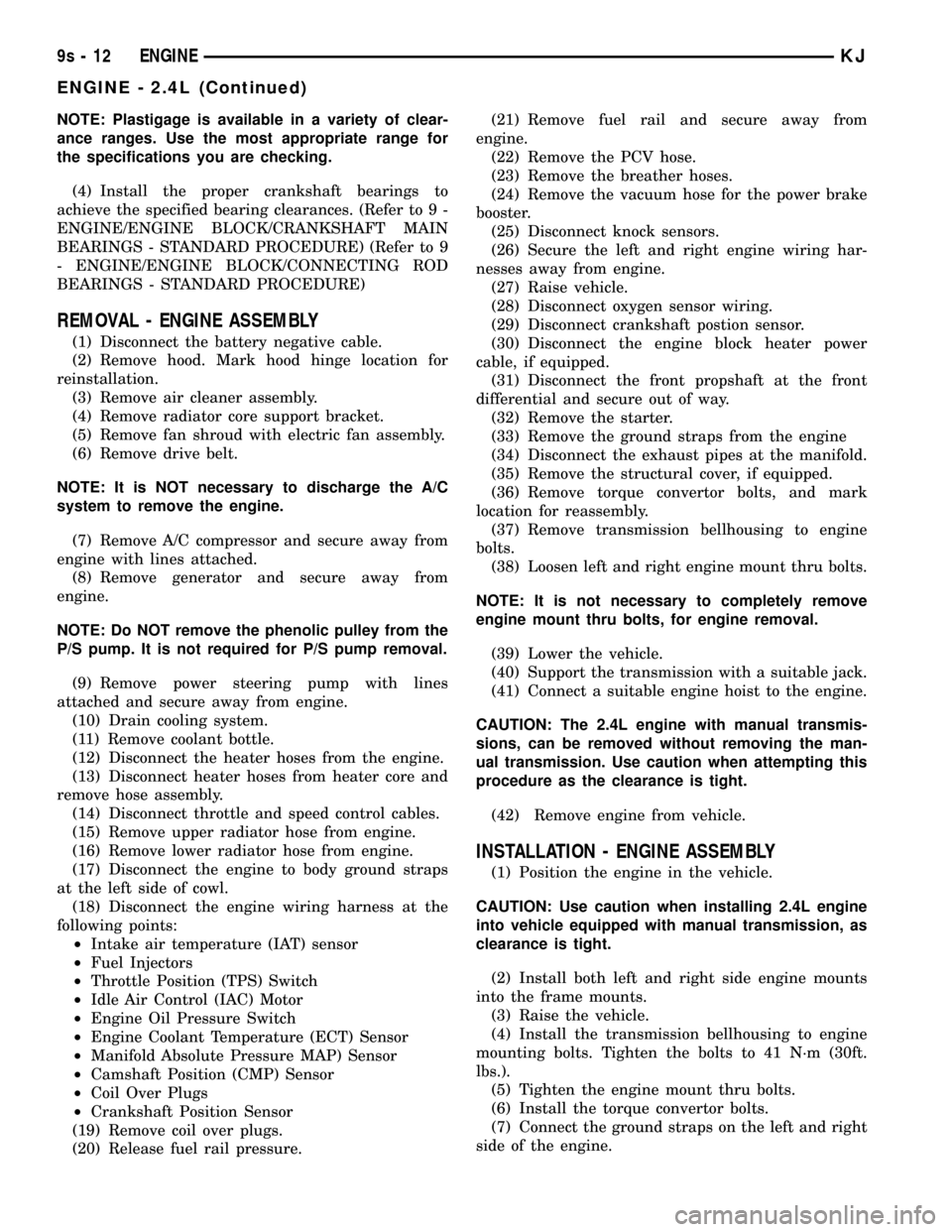
NOTE: Plastigage is available in a variety of clear-
ance ranges. Use the most appropriate range for
the specifications you are checking.
(4) Install the proper crankshaft bearings to
achieve the specified bearing clearances. (Refer to 9 -
ENGINE/ENGINE BLOCK/CRANKSHAFT MAIN
BEARINGS - STANDARD PROCEDURE) (Refer to 9
- ENGINE/ENGINE BLOCK/CONNECTING ROD
BEARINGS - STANDARD PROCEDURE)
REMOVAL - ENGINE ASSEMBLY
(1) Disconnect the battery negative cable.
(2) Remove hood. Mark hood hinge location for
reinstallation.
(3) Remove air cleaner assembly.
(4) Remove radiator core support bracket.
(5) Remove fan shroud with electric fan assembly.
(6) Remove drive belt.
NOTE: It is NOT necessary to discharge the A/C
system to remove the engine.
(7) Remove A/C compressor and secure away from
engine with lines attached.
(8) Remove generator and secure away from
engine.
NOTE: Do NOT remove the phenolic pulley from the
P/S pump. It is not required for P/S pump removal.
(9) Remove power steering pump with lines
attached and secure away from engine.
(10) Drain cooling system.
(11) Remove coolant bottle.
(12) Disconnect the heater hoses from the engine.
(13) Disconnect heater hoses from heater core and
remove hose assembly.
(14) Disconnect throttle and speed control cables.
(15) Remove upper radiator hose from engine.
(16) Remove lower radiator hose from engine.
(17) Disconnect the engine to body ground straps
at the left side of cowl.
(18) Disconnect the engine wiring harness at the
following points:
²Intake air temperature (IAT) sensor
²Fuel Injectors
²Throttle Position (TPS) Switch
²Idle Air Control (IAC) Motor
²Engine Oil Pressure Switch
²Engine Coolant Temperature (ECT) Sensor
²Manifold Absolute Pressure MAP) Sensor
²Camshaft Position (CMP) Sensor
²Coil Over Plugs
²Crankshaft Position Sensor
(19) Remove coil over plugs.
(20) Release fuel rail pressure.(21) Remove fuel rail and secure away from
engine.
(22) Remove the PCV hose.
(23) Remove the breather hoses.
(24) Remove the vacuum hose for the power brake
booster.
(25) Disconnect knock sensors.
(26) Secure the left and right engine wiring har-
nesses away from engine.
(27) Raise vehicle.
(28) Disconnect oxygen sensor wiring.
(29) Disconnect crankshaft postion sensor.
(30) Disconnect the engine block heater power
cable, if equipped.
(31) Disconnect the front propshaft at the front
differential and secure out of way.
(32) Remove the starter.
(33) Remove the ground straps from the engine
(34) Disconnect the exhaust pipes at the manifold.
(35) Remove the structural cover, if equipped.
(36) Remove torque convertor bolts, and mark
location for reassembly.
(37) Remove transmission bellhousing to engine
bolts.
(38) Loosen left and right engine mount thru bolts.
NOTE: It is not necessary to completely remove
engine mount thru bolts, for engine removal.
(39) Lower the vehicle.
(40) Support the transmission with a suitable jack.
(41) Connect a suitable engine hoist to the engine.
CAUTION: The 2.4L engine with manual transmis-
sions, can be removed without removing the man-
ual transmission. Use caution when attempting this
procedure as the clearance is tight.
(42) Remove engine from vehicle.
INSTALLATION - ENGINE ASSEMBLY
(1) Position the engine in the vehicle.
CAUTION: Use caution when installing 2.4L engine
into vehicle equipped with manual transmission, as
clearance is tight.
(2) Install both left and right side engine mounts
into the frame mounts.
(3) Raise the vehicle.
(4) Install the transmission bellhousing to engine
mounting bolts. Tighten the bolts to 41 N´m (30ft.
lbs.).
(5) Tighten the engine mount thru bolts.
(6) Install the torque convertor bolts.
(7) Connect the ground straps on the left and right
side of the engine.
9s - 12 ENGINEKJ
ENGINE - 2.4L (Continued)
Page 1310 of 1803
(8) Install the starter.
(9) Connect the crankshaft position sensor.
(10) Install the engine block heater power cable, if
equipped.
CAUTION: The structural cover requires a specific
torque sequence. Failure to follow this sequence
may cause severe damage to the cover.
(11) Install the structural cover.
(12) Install the exhaust pipe.
(13) Connect the oxygen sensors.
(14) Lower vehicle.
(15) Connect the knock sensors.
(16) Connect the engine to body ground straps.
(17) Install the power brake booster vacuum hose.
(18) Install the breather hoses.
(19) Install the PCV hose.
(20) Install the fuel rail.
(21) Install the coil over plugs.
(22) Reconnect the engine wiring harness at the
following points:
²Intake air temperature (IAT) sensor
²Fuel Injectors
²Throttle Position (TPS) Switch
²Idle Air Control (IAC) Motor
²Engine Oil Pressure Switch
²Engine Coolant Temperature (ECT) Sensor
²Manifold Absolute Pressure MAP) Sensor
²Camshaft Position (CMP) Sensor
²Coil Over Plugs
²Crankshaft Position Sensor
(23) Connect lower radiator hose.
(24) Connect upper radiator hose.
(25) Connect throttle and speed control cables.
(26) Install the heater hose assembly.
(27) Install coolant recovery bottle.
(28) Install the power steering pump.
(29) Install the generator.
(30) Install the A/C compressor.
(31) Install the drive belt.
(32) Install the fan shroud with the electric fan
assembly.
(33) Install the radiator core support bracket.
(34) Install the air cleaner assembly.
(35) Refill the engine cooling system.
(36) Install the hood.
(37) Check and fill engine oil.
(38) Connect the battery negative cable.
(39) Start the engine and check for leaks.SPECIFICATIONS
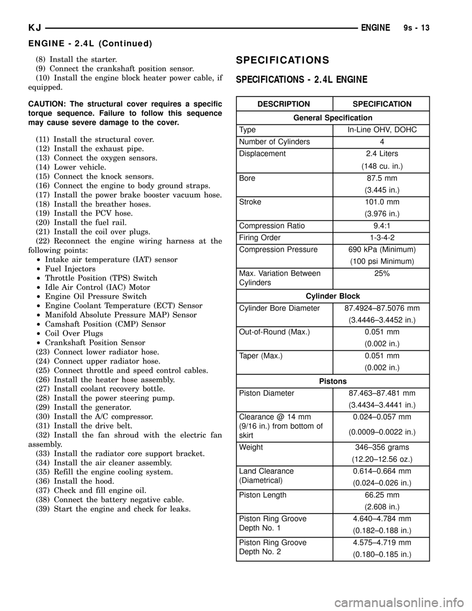
SPECIFICATIONS - 2.4L ENGINE
DESCRIPTION SPECIFICATION
General Specification
Type In-Line OHV, DOHC
Number of Cylinders 4
Displacement 2.4 Liters
(148 cu. in.)
Bore 87.5 mm
(3.445 in.)
Stroke 101.0 mm
(3.976 in.)
Compression Ratio 9.4:1
Firing Order 1-3-4-2
Compression Pressure 690 kPa (Minimum)
(100 psi Minimum)
Max. Variation Between
Cylinders25%
Cylinder Block
Cylinder Bore Diameter 87.4924±87.5076 mm
(3.4446±3.4452 in.)
Out-of-Round (Max.) 0.051 mm
(0.002 in.)
Taper (Max.) 0.051 mm
(0.002 in.)
Pistons
Piston Diameter 87.463±87.481 mm
(3.4434±3.4441 in.)
Clearance @ 14 mm
(9/16 in.) from bottom of
skirt0.024±0.057 mm
(0.0009±0.0022 in.)
Weight 346±356 grams
(12.20±12.56 oz.)
Land Clearance
(Diametrical)0.614±0.664 mm
(0.024±0.026 in.)
Piston Length 66.25 mm
(2.608 in.)
Piston Ring Groove
Depth No. 14.640±4.784 mm
(0.182±0.188 in.)
Piston Ring Groove
Depth No. 24.575±4.719 mm
(0.180±0.185 in.)
KJENGINE9s-13
ENGINE - 2.4L (Continued)