2002 JEEP GRAND CHEROKEE rear main bearing cap
[x] Cancel search: rear main bearing capPage 106 of 2199

(8) Thread Pilot Stud C-3288-B into rear cover bolt
hole below ring gear (Fig. 17).
(9) Attach a Dial Indicator C-3339 to pilot stud.
Position the dial indicator plunger on a flat surface
between the ring gear bolt heads (Fig. 17).
(10) Push and hold differential case to pinion gear
side of the housing and zero dial indicator (Fig. 18).
(11) Push and hold differential case to ring gear
side of the housing and record dial indicator reading
(Fig. 19).
(12) Add 0.152 mm (0.006 in.) to the zero end play
total. This new total represents the thickness of
shims to compress, or preload the new bearings when
the differential is installed.
(13) Rotate dial indicator out of the way on the
pilot stud.
(14) Remove differential case and dummy bearings
from the housing.
(15) Install the pinion gear in axle housing. Install
the pinion yoke and establish the correct pinion
rotating torque.
(16) Install differential case and Dummy Bearings
D-348 in the housing.
(17) Install a single dummy shim in the ring gear
side. Install bearing caps and tighten bolts snug.
(18) Seat ring gear side dummy bearing (Fig. 16).
(19) Position the dial indicator plunger on a flat
surface between the ring gear bolt heads. (Fig. 17).(20) Push and hold differential case toward pinion
gear and zero dial indicator (Fig. 20).
(21) Push and hold differential case to ring gear
side of the housing and record dial indicator reading
(Fig. 21). Add dummy shim thickness to this reading.
This will be the total shim thickness to achieve zero
backlash.
(22) Subtract 0.076 mm (0.003 in.) from the dial
indicator reading to compensate for backlash between
ring and pinion gears. This total is the thickness
shim required to achieve proper backlash.
(23) Subtract the backlash shim thickness from
the total preload shim thickness. The remainder is
Fig. 17 DIFFERENTIAL SIDE PLAY
1 - DIFFERENTIAL CASE
2 - DIFFERENTIAL HOUSING
3 - PILOT STUD
4 - DIAL INDICATOR
Fig. 18 ZERO DIAL INDICATOR
1 - FORCE DIFFERENTIAL CASE TO PINION GEAR SIDE
2 - PILOT STUD
3 - DIAL INDICATOR
4 - ZERO DIAL INDICATOR FACE
Fig. 19 DIFFERENTIAL TO RING GEAR SIDE
1 - DIAL INDICATOR
2 - FORCE DIFFERENTIAL CASE TO RING GEAR SIDE
3 - DIFFERENTIAL HOUSING
WJREAR AXLE - 198RBI 3 - 61
REAR AXLE - 198RBI (Continued)
Page 122 of 2199
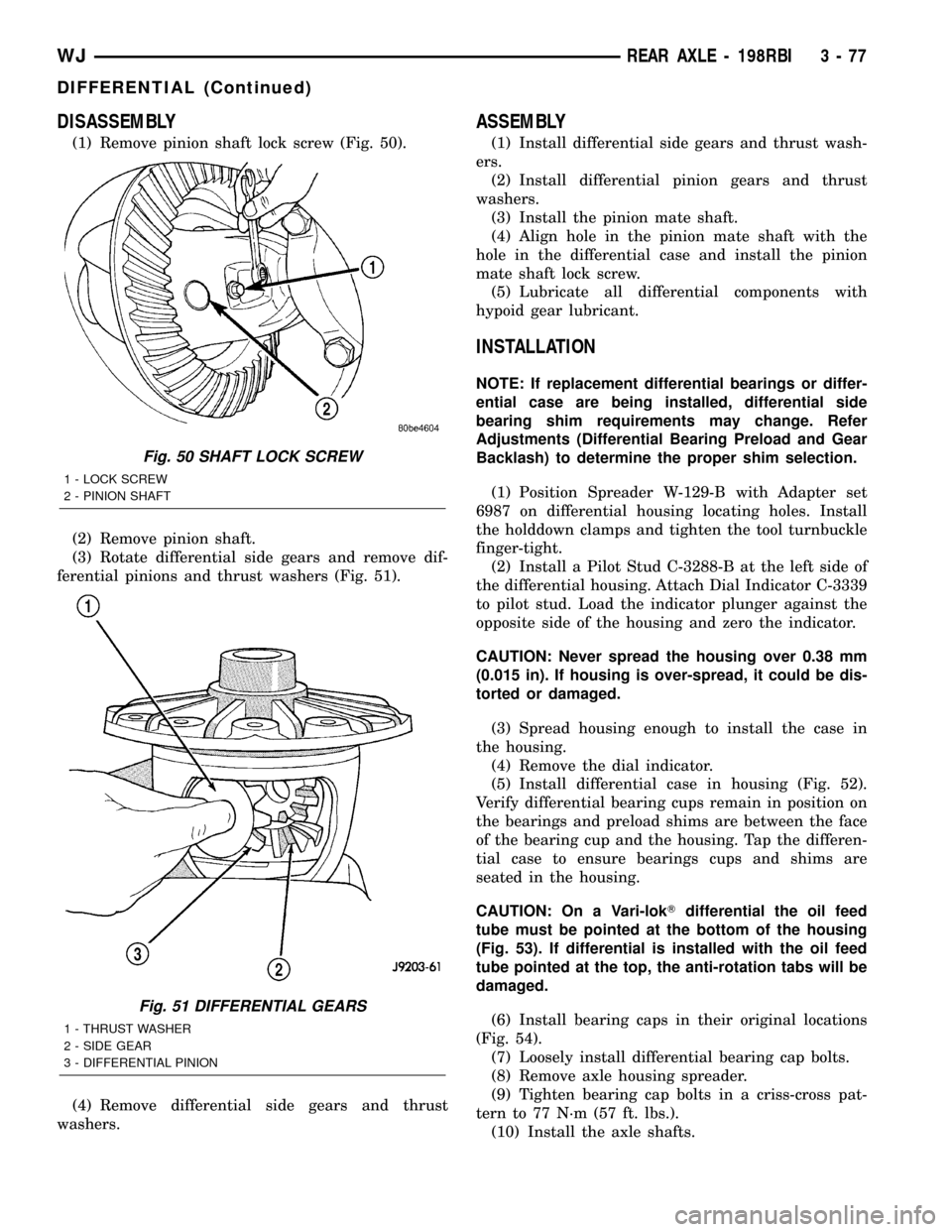
DISASSEMBLY
(1) Remove pinion shaft lock screw (Fig. 50).
(2) Remove pinion shaft.
(3) Rotate differential side gears and remove dif-
ferential pinions and thrust washers (Fig. 51).
(4) Remove differential side gears and thrust
washers.
ASSEMBLY
(1) Install differential side gears and thrust wash-
ers.
(2) Install differential pinion gears and thrust
washers.
(3) Install the pinion mate shaft.
(4) Align hole in the pinion mate shaft with the
hole in the differential case and install the pinion
mate shaft lock screw.
(5) Lubricate all differential components with
hypoid gear lubricant.
INSTALLATION
NOTE: If replacement differential bearings or differ-
ential case are being installed, differential side
bearing shim requirements may change. Refer
Adjustments (Differential Bearing Preload and Gear
Backlash) to determine the proper shim selection.
(1) Position Spreader W-129-B with Adapter set
6987 on differential housing locating holes. Install
the holddown clamps and tighten the tool turnbuckle
finger-tight.
(2) Install a Pilot Stud C-3288-B at the left side of
the differential housing. Attach Dial Indicator C-3339
to pilot stud. Load the indicator plunger against the
opposite side of the housing and zero the indicator.
CAUTION: Never spread the housing over 0.38 mm
(0.015 in). If housing is over-spread, it could be dis-
torted or damaged.
(3) Spread housing enough to install the case in
the housing.
(4) Remove the dial indicator.
(5) Install differential case in housing (Fig. 52).
Verify differential bearing cups remain in position on
the bearings and preload shims are between the face
of the bearing cup and the housing. Tap the differen-
tial case to ensure bearings cups and shims are
seated in the housing.
CAUTION: On a Vari-lokTdifferential the oil feed
tube must be pointed at the bottom of the housing
(Fig. 53). If differential is installed with the oil feed
tube pointed at the top, the anti-rotation tabs will be
damaged.
(6) Install bearing caps in their original locations
(Fig. 54).
(7) Loosely install differential bearing cap bolts.
(8) Remove axle housing spreader.
(9) Tighten bearing cap bolts in a criss-cross pat-
tern to 77 N´m (57 ft. lbs.).
(10) Install the axle shafts.
Fig. 50 SHAFT LOCK SCREW
1 - LOCK SCREW
2 - PINION SHAFT
Fig. 51 DIFFERENTIAL GEARS
1 - THRUST WASHER
2 - SIDE GEAR
3 - DIFFERENTIAL PINION
WJREAR AXLE - 198RBI 3 - 77
DIFFERENTIAL (Continued)
Page 140 of 2199

Condition Possible Causes Correction
Gear Teeth Broke 1. Overloading. 1. Replace gears. Examine other
gears and bearings for possible
damage.
2. Erratic clutch operation. 2. Replace gears and examine the
remaining parts for damage. Avoid
erratic clutch operation.
3. Ice-spotted pavement. 3. Replace gears and examine
remaining parts for damage.
4. Improper adjustments. 4. Replace gears and examine
remaining parts for damage. Ensure
ring gear backlash is correct.
Axle Noise 1. Insufficient lubricant. 1. Fill differential with the correct
fluid type and quantity.
2. Improper ring gear and pinion
adjustment.2. Check ring gear and pinion
contact pattern.
3. Unmatched ring gear and pinion. 3. Replace gears with a matched
ring gear and pinion.
4. Worn teeth on ring gear and/or
pinion.4. Replace ring gear and pinion.
5. Loose pinion bearings. 5. Adjust pinion bearing pre-load.
6. Loose differential bearings. 6. Adjust differential bearing
pre-load.
7. Mis-aligned or sprung ring gear. 7. Measure ring gear run-out.
Replace components as necessary.
8. Loose differential bearing cap
bolts.8. Inspect differential components
and replace as necessary. Ensure
that the bearing caps are torqued
tot he proper specification.
9. Housing not machined properly. 9. Replace housing.
VARI-LOKT
(1) Park the vehicle on a level surface or raise
vehicle on hoist so that the vehicle is level.
(2) Remove the axle fill plug.
(3) Verify that the axle fluid level is correct. The
fluid level is correct if the fluid is level with the bot-
tom of the fill hole.
(4) Shift the transfer case into the 4WD full-time
position.
(5) Drive the vehicle in a tight circle for 2 minutes
at 5mph to fully prime the pump.
(6) Block the tires opposite the axle to be tested to
prevent the vehicle from moving.
(7) Shift the transfer case into the 4WD Low posi-
tion and the transmission into the Park position.
(8) Raise both the wheels of the axle to be tested
off of the ground.(9) Rotate the left wheel by hand at a minimum of
one revolution per second while an assistant rotates
the right wheel in the opposite direction.
(10) The left wheel should spin freely at first and
then increase in resistance within 5 revolutions until
the wheels cannot be continuously rotated in opposite
directions.
(11) The Vari-loktdifferential has engaged prop-
erly if the wheels cannot be rotated in opposite direc-
tions for a moment. After the wheels stop rotating for
a moment, the fluid pressure will drop in the differ-
ential and the wheels begin to rotate once again.
(12) If the system does not operate properly,
replace the Vari-loktdifferential.
REMOVAL
(1) Raise and support the vehicle.
(2) Position a lifting device under the axle and
secure axle.
WJREAR AXLE - 226RBA 3 - 95
REAR AXLE - 226RBA (Continued)
Page 147 of 2199
(14) Remove differential case and dummy bearings
from the housing.
(15) Install the pinion gear in the housing. Install
the pinion yoke and establish the correct pinion
rotating torque.
(16) Install differential case and Dummy Bearings
6929-A in the housing.
(17) Install a single dummy shim in the ring gear
side. Install bearing caps and tighten bolts snug.
(18) Seat ring gear side dummy bearing (Fig. 16).
(19) Position the dial indicator plunger on a flat
surface between the ring gear bolt heads. (Fig. 17).
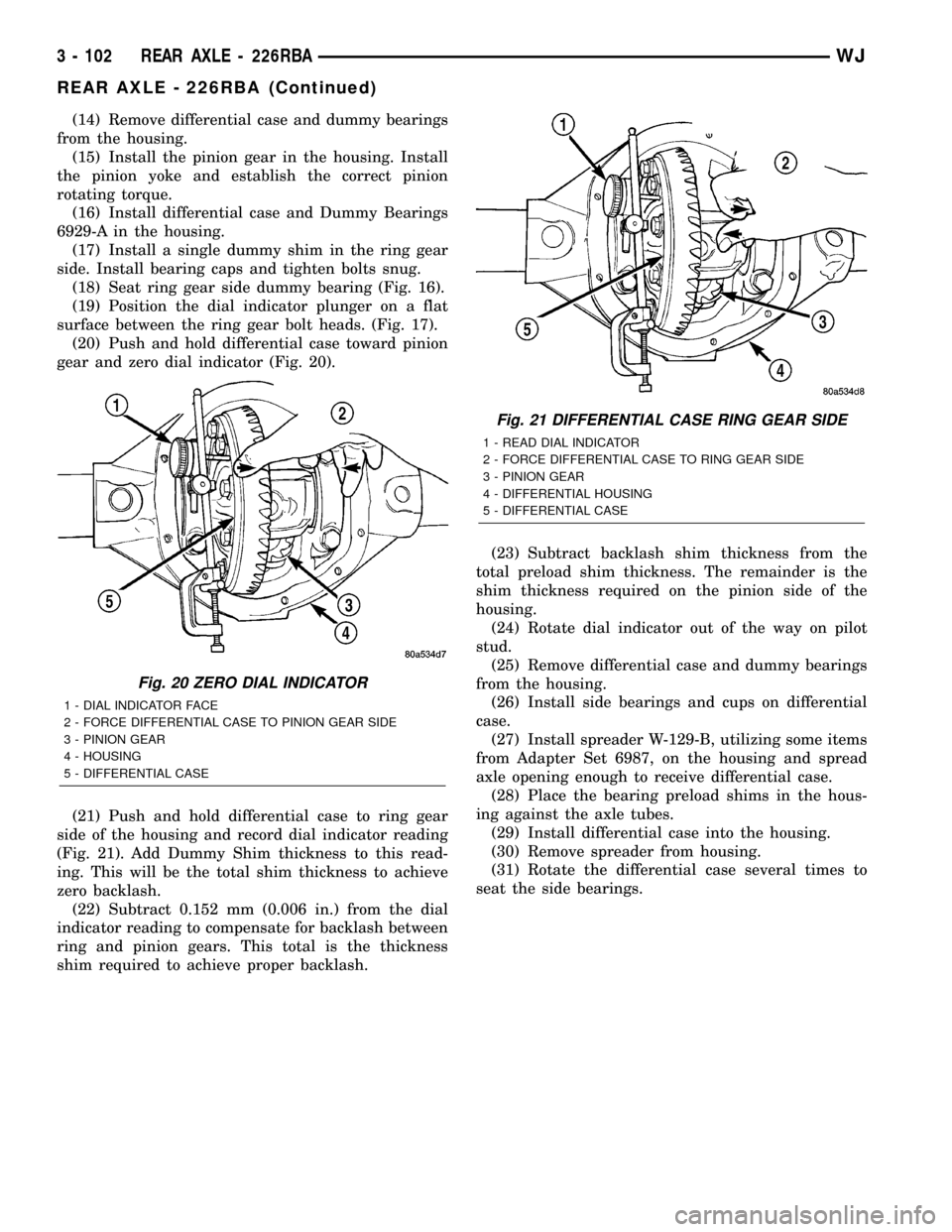
(20) Push and hold differential case toward pinion
gear and zero dial indicator (Fig. 20).
(21) Push and hold differential case to ring gear
side of the housing and record dial indicator reading
(Fig. 21). Add Dummy Shim thickness to this read-
ing. This will be the total shim thickness to achieve
zero backlash.
(22) Subtract 0.152 mm (0.006 in.) from the dial
indicator reading to compensate for backlash between
ring and pinion gears. This total is the thickness
shim required to achieve proper backlash.(23) Subtract backlash shim thickness from the
total preload shim thickness. The remainder is the
shim thickness required on the pinion side of the
housing.
(24) Rotate dial indicator out of the way on pilot
stud.
(25) Remove differential case and dummy bearings
from the housing.
(26) Install side bearings and cups on differential
case.
(27) Install spreader W-129-B, utilizing some items
from Adapter Set 6987, on the housing and spread
axle opening enough to receive differential case.
(28) Place the bearing preload shims in the hous-
ing against the axle tubes.
(29) Install differential case into the housing.
(30) Remove spreader from housing.
(31) Rotate the differential case several times to
seat the side bearings.
Fig. 20 ZERO DIAL INDICATOR
1 - DIAL INDICATOR FACE
2 - FORCE DIFFERENTIAL CASE TO PINION GEAR SIDE
3 - PINION GEAR
4 - HOUSING
5 - DIFFERENTIAL CASE
Fig. 21 DIFFERENTIAL CASE RING GEAR SIDE
1 - READ DIAL INDICATOR
2 - FORCE DIFFERENTIAL CASE TO RING GEAR SIDE
3 - PINION GEAR
4 - DIFFERENTIAL HOUSING
5 - DIFFERENTIAL CASE
3 - 102 REAR AXLE - 226RBAWJ
REAR AXLE - 226RBA (Continued)
Page 162 of 2199
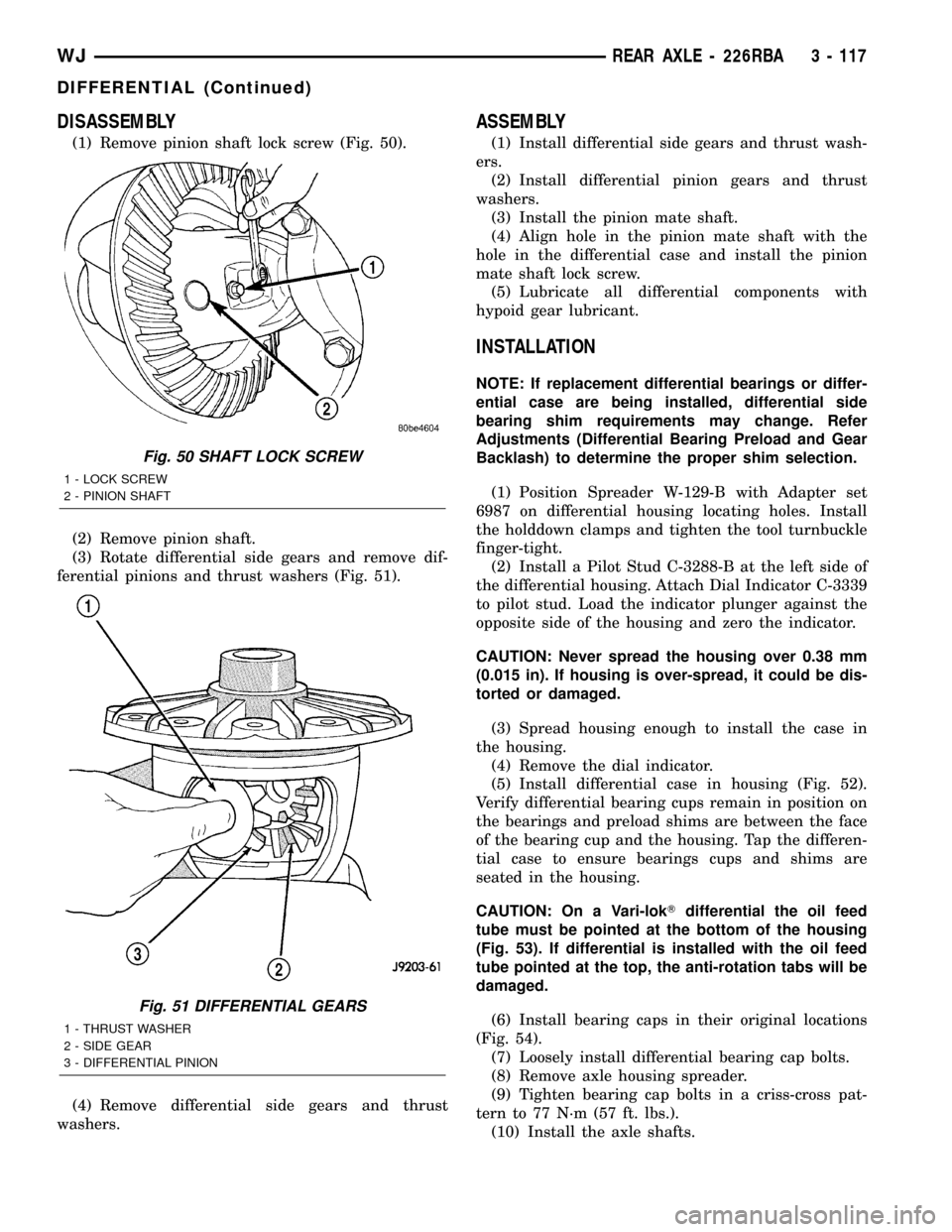
DISASSEMBLY
(1) Remove pinion shaft lock screw (Fig. 50).
(2) Remove pinion shaft.
(3) Rotate differential side gears and remove dif-
ferential pinions and thrust washers (Fig. 51).
(4) Remove differential side gears and thrust
washers.
ASSEMBLY
(1) Install differential side gears and thrust wash-
ers.
(2) Install differential pinion gears and thrust
washers.
(3) Install the pinion mate shaft.
(4) Align hole in the pinion mate shaft with the
hole in the differential case and install the pinion
mate shaft lock screw.
(5) Lubricate all differential components with
hypoid gear lubricant.
INSTALLATION
NOTE: If replacement differential bearings or differ-
ential case are being installed, differential side
bearing shim requirements may change. Refer
Adjustments (Differential Bearing Preload and Gear
Backlash) to determine the proper shim selection.
(1) Position Spreader W-129-B with Adapter set
6987 on differential housing locating holes. Install
the holddown clamps and tighten the tool turnbuckle
finger-tight.
(2) Install a Pilot Stud C-3288-B at the left side of
the differential housing. Attach Dial Indicator C-3339
to pilot stud. Load the indicator plunger against the
opposite side of the housing and zero the indicator.
CAUTION: Never spread the housing over 0.38 mm
(0.015 in). If housing is over-spread, it could be dis-
torted or damaged.
(3) Spread housing enough to install the case in
the housing.
(4) Remove the dial indicator.
(5) Install differential case in housing (Fig. 52).
Verify differential bearing cups remain in position on
the bearings and preload shims are between the face
of the bearing cup and the housing. Tap the differen-
tial case to ensure bearings cups and shims are
seated in the housing.
CAUTION: On a Vari-lokTdifferential the oil feed
tube must be pointed at the bottom of the housing
(Fig. 53). If differential is installed with the oil feed
tube pointed at the top, the anti-rotation tabs will be
damaged.
(6) Install bearing caps in their original locations
(Fig. 54).
(7) Loosely install differential bearing cap bolts.
(8) Remove axle housing spreader.
(9) Tighten bearing cap bolts in a criss-cross pat-
tern to 77 N´m (57 ft. lbs.).
(10) Install the axle shafts.
Fig. 50 SHAFT LOCK SCREW
1 - LOCK SCREW
2 - PINION SHAFT
Fig. 51 DIFFERENTIAL GEARS
1 - THRUST WASHER
2 - SIDE GEAR
3 - DIFFERENTIAL PINION
WJREAR AXLE - 226RBA 3 - 117
DIFFERENTIAL (Continued)
Page 208 of 2199
STANDARD PROCEDURE - DISC ROTOR
MACHINING
CAUTION: For vehicles equipped with the Quadra-
Drive System, consisting of the NV-247 transfer case
and a Vari-Lok differential in the front and rear axles,
the following steps must be done prior to the use of a
hub mounted on-vehicle brake lathe. Disconnect the
driveshaft (Refer to 3 - DIFFERENTIAL & DRIVELINE/
PROPELLER SHAFT/PROPELLER SHAFT - REMOVAL)
from the respective axle on which the brake rotors are
being machined. Temporarily remove both brake cali-
pers (Refer to 5 - BRAKES/HYDRAULIC/MECHANICAL/
DISC BRAKE CALIPERS - REMOVAL) from the axle
while disc rotor machining is in process. Both steps
will prevent unnecessary loads to the hub mounted
on-vehicle lathe and speed machining times. Install a
thread lock material to the driveshaft attaching bolts
when reinstalling (Refer to 3 - DIFFERENTIAL & DRIV-
ELINE/PROPELLER SHAFT/PROPELLER SHAFT -
INSTALLATION).
NOTE: A hub mounted on-vehicle lathe is recom-
mended. This type of lathe trues the rotor to the vehi-
cles hub/bearing.
The disc brake rotor can be machined if scored or
worn. The lathe must machine both sides of the rotor
simultaneously with dual cutter heads. The rotor
mounting surface must be clean before placing on the
lathe. Equipment capable of machining only one side at
a time may produce a tapered rotor.
CAUTION: Brake rotors that do not meet minimum
thickness specifications before or after machining
must be replaced.
REMOVAL
REMOVAL - FRONT DISC BRAKE ROTOR
NOTE: Front rotors and hub/bearings are matched
mounted for minimum lateral runout. Before removing
the rotor, mark the rotor and hub/bearing to maintain
original orientation.
(1) Raise and support the vehicle.
(2) Remove wheel and tire assembly.
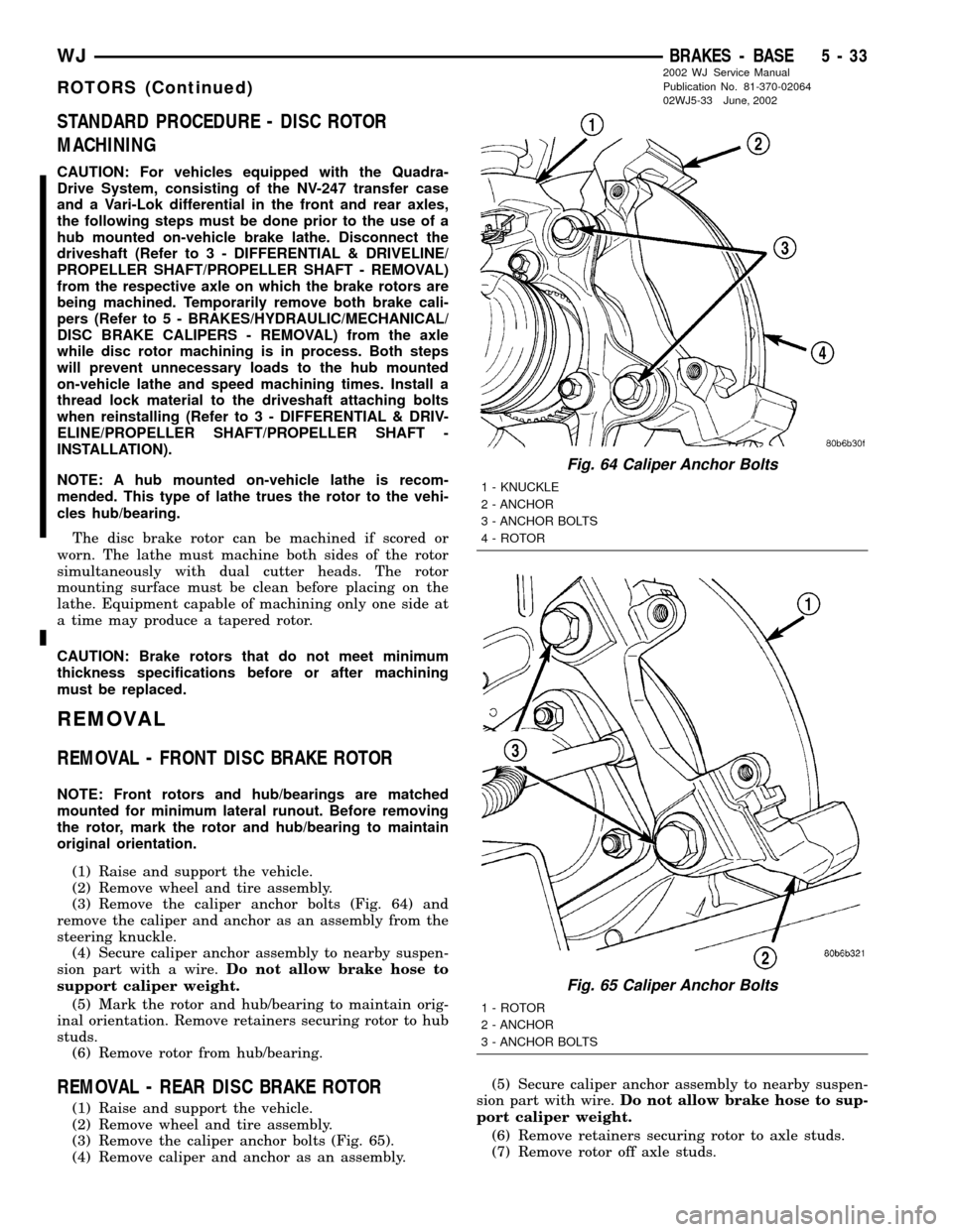
(3) Remove the caliper anchor bolts (Fig. 64) and
remove the caliper and anchor as an assembly from the
steering knuckle.
(4) Secure caliper anchor assembly to nearby suspen-
sion part with a wire.Do not allow brake hose to
support caliper weight.
(5) Mark the rotor and hub/bearing to maintain orig-
inal orientation. Remove retainers securing rotor to hub
studs.
(6) Remove rotor from hub/bearing.
REMOVAL - REAR DISC BRAKE ROTOR
(1) Raise and support the vehicle.
(2) Remove wheel and tire assembly.
(3) Remove the caliper anchor bolts (Fig. 65).
(4) Remove caliper and anchor as an assembly.(5) Secure caliper anchor assembly to nearby suspen-
sion part with wire.Do not allow brake hose to sup-
port caliper weight.
(6) Remove retainers securing rotor to axle studs.
(7) Remove rotor off axle studs.
Fig. 64 Caliper Anchor Bolts
1 - KNUCKLE
2 - ANCHOR
3 - ANCHOR BOLTS
4 - ROTOR
Fig. 65 Caliper Anchor Bolts
1 - ROTOR
2 - ANCHOR
3 - ANCHOR BOLTS
WJBRAKES - BASE 5 - 33
ROTORS (Continued)
2002 WJ Service Manual
Publication No. 81-370-02064
02WJ5-33 June, 2002
Page 1252 of 2199
DIAGNOSIS AND TESTINGÐREAR SEAL AREA
LEAKS
Since it is sometimes difficult to determine the
source of an oil leak in the rear seal area of the
engine, a more involved inspection is necessary. The
following steps should be followed to help pinpoint
the source of the leak.
If the leakage occurs at the crankshaft rear oil seal
area:
(1) Disconnect the battery.
(2) Raise the vehicle.
(3) Remove torque converter or clutch housing
cover and inspect rear of block for evidence of oil.
Use a black light to check for the oil leak:
(a) Circular spray pattern generally indicates
seal leakage or crankshaft damage.
(b) Where leakage tends to run straight down,
possible causes are a porous block, distributor seal,
camshaft bore cup plugs, oil galley pipe plugs, oil
filter runoff, and main bearing cap to cylinder
block mating surfaces.
(4) If no leaks are detected, pressurized the crank-
case as outlined in (Refer to 9 - ENGINE/LUBRICA-
TION - DIAGNOSIS AND TESTING)
CAUTION: Do not exceed 20.6 kPa (3 psi).
(5) If the leak is not detected, very slowly turn the
crankshaft and watch for leakage. If a leak is
detected between the crankshaft and seal while
slowly turning the crankshaft, it is possible the
crankshaft seal surface is damaged. The seal area on
the crankshaft could have minor nicks or scratches
that can be polished out with emery cloth.
CAUTION: Use extreme caution when crankshaft
polishing is necessary to remove minor nicks or
scratches. The crankshaft seal flange is specially
machined to complement the function of the rear oil
seal.
(6) For bubbles that remain steady with shaft
rotation, no further inspection can be done until dis-
assembled. Refer to the service DiagnosisÐMechani-
cal, under the Oil Leak row, for components
inspections on possible causes and corrections.
(7) After the oil leak root cause and appropriate
corrective action have been identified, (Refer to 9 -
ENGINE/ENGINE BLOCK/CRANKSHAFT OIL
SEAL - REAR - REMOVAL), for proper replacement
procedures.
STANDARD PROCEDURE
STANDARD PROCEDURE - FORM-IN-PLACE
GASKETS AND SEALERS
There are numerous places where form-in-place
gaskets are used on the engine. Care must be taken
when applying form-in-place gaskets to assure
obtaining the desired results.Do not use form-in-
place gasket material unless specified.Bead size,
continuity, and location are of great importance. Too
thin a bead can result in leakage while too much can
result in spill-over which can break off and obstruct
fluid feed lines. A continuous bead of the proper
width is essential to obtain a leak-free gasket.
There are numerous types of form-in-place gasket
materials that are used in the engine area. Mopart
Engine RTV GEN II, MopartATF-RTV, and Mopart
Gasket Maker gasket materials, each have different
properties and can not be used in place of the other.
MOPARtENGINE RTV GEN II
MopartEngine RTV GEN II is used to seal com-
ponents exposed to engine oil. This material is a spe-
cially designed black silicone rubber RTV that
retains adhesion and sealing properties when
exposed to engine oil. Moisture in the air causes the
material to cure. This material is available in three
ounce tubes and has a shelf life of one year. After one
year this material will not properly cure. Always
inspect the package for the expiration date before
use.
MOPARtATF RTV
MopartATF RTV is a specifically designed black
silicone rubber RTV that retains adhesion and seal-
ing properties to seal components exposed to auto-
matic transmission fluid, engine coolants, and
moisture. This material is available in three ounce
tubes and has a shelf life of one year. After one year
this material will not properly cure. Always inspect
the package for the expiration date before use.
MOPARtGASKET MAKER
MopartGasket Maker is an anaerobic type gasket
material. The material cures in the absence of air
when squeezed between two metallic surfaces. It will
not cure if left in the uncovered tube. The anaerobic
material is for use between two machined surfaces.
Do not use on flexible metal flanges.
MOPARtGASKET SEALANT
MopartGasket Sealant is a slow drying, perma-
nently soft sealer. This material is recommended for
sealing threaded fittings and gaskets against leakage
of oil and coolant. Can be used on threaded and
machined parts under all temperatures. This mate-
rial is used on engines with multi-layer steel (MLS)
cylinder head gaskets. This material also will pre-
vent corrosion. MopartGasket Sealant is available in
a 13 oz. aerosol can or 4oz./16 oz. can w/applicator.
WJENGINE - 4.0L 9 - 9
ENGINE - 4.0L (Continued)
Page 1273 of 2199
ENGINE BLOCK
CLEANING
Thoroughly clean the oil pan and engine block gas-
ket surfaces.
Use compressed air to clean out:
²The galley at the oil filter adaptor hole.
²The front and rear oil galley holes.
²The feed holes for the crankshaft main bearings.
Once the block has been completely cleaned, apply
Loctite PST pipe sealant with Teflon 592 to the
threads of the front and rear oil galley plugs. Tighten
the plugs to 34 N´m (25 ft. lbs.) torque.
INSPECTION
(1) It is mandatory to use a dial bore gauge to
measure each cylinder bore diameter (Fig. 29). To
correctly select the proper size piston, a cylinder bore
gauge, capable of reading in 0.003 mm (.0001 in.)
INCREMENTS is required. If a bore gauge is not
available, do not use an inside micrometer.
(2) Measure the inside diameter of the cylinder
bore at three levels below top of bore. Start perpen-
dicular (across or at 90 degrees) to the axis of the
crankshaft and then take two additional reading.(3) Measure the cylinder bore diameter crosswise
to the cylinder block near the top of the bore. Repeat
the measurement near the middle of the bore, then
repeat the measurement near the bottom of the bore.
(4) Determine taper by subtracting the smaller
diameter from the larger diameter.
(5) Rotate measuring device 90É and repeat steps
above.
(6) Determine out-of-roundness by comparing the
difference between each measurement.
(7) If cylinder bore taper does not exceed 0.025
mm (0.001 inch) and out-of-roundness does not
exceed 0.025 mm (0.001 inch), the cylinder bore can
be honed. If the cylinder bore taper or out- of-round
condition exceeds these maximum limits, the cylinder
must be bored and then honed to accept an oversize
piston. A slight amount of taper always exists in the
cylinder bore after the engine has been in use for a
period of time.
CAMSHAFT & BEARINGS
DESCRIPTION
The camshaft is made of gray cast iron with twelve
machined lobes and four bearing journals (Fig. 30).
When the camshaft rotates the lobes actuate the tap-
pets and push rods, forcing upward on the rocker
arms which applies downward force on the valves.
Fig. 28 Valve and Valve
1 - VALVE LOCKS (3±BEAD)
2 - RETAINER
3 - VALVE STEM OIL SEAL
4 - INTAKE VALVE
5 - EXHAUST VALVE
6 - VALVE SPRINGFig. 29 Cylinder Bore Measurement
9 - 30 ENGINE - 4.0LWJ
VALVE SPRINGS (Continued)