2002 JEEP GRAND CHEROKEE Control
[x] Cancel search: ControlPage 1 of 2199

GROUP TAB LOCATOR
Introduction
0Lubrication & Maintenance
2Suspension
3Driveline
5Brakes
7Cooling
8AAudio
8BChime/Buzzer
8EElectronic Control Modules
8FEngine Systems
8GHeated Systems
8HHorn
8IIgnition Control
8JInstrument Cluster
8LLamps
8MMessage Systems
8NPower Systems
8ORestraints
8PSpeed Control
8QVehicle Theft Security
8RWipers/Washers
8WWiring
9Engine
11Exhaust System
13Frame & Bumpers
14Fuel System
19Steering
21Transaxle
22Tires/Wheels
23Body
24Heating & Air Conditioning
25Emissions Control
Service Manual Comment Forms (Rear of Manual)
Page 2 of 2199

INTRODUCTION
TABLE OF CONTENTS
page page
BODY CODE PLATE
DESCRIPTION..........................1
FASTENER IDENTIFICATION
DESCRIPTION..........................1
FASTENER USAGE
DESCRIPTION - FASTENER USAGE.........4
THREADED HOLE REPAIR
DESCRIPTION - THREADED HOLE REPAIR....4
INTERNATIONAL SYMBOLS
DESCRIPTION - INTERNATIONAL SYMBOLS . . . 4
METRIC SYSTEM
DESCRIPTION..........................5TORQUE REFERENCES
DESCRIPTION..........................7
VEHICLE EMISSION CONTROL INFORMATION
(VECI)
DESCRIPTION..........................8
VEHICLE IDENTIFICATION NUMBER
DESCRIPTION..........................8
VEHICLE SAFETY CERTIFICATION LABEL
DESCRIPTION..........................9
BODY CODE PLATE
DESCRIPTION
A metal Body Code plate is located in the engine
compartment and attached to the top of the right
frame rail. The information listed on the plate (Fig.
1) is used for manufacturing and service purposes.
FASTENER IDENTIFICATION
DESCRIPTION
The SAE bolt strength grades range from grade 2
to grade 8. The higher the grade number, the greater
the bolt strength. Identification is determined by the
line marks on the top of each bolt head. The actual
bolt strength grade corresponds to the number of line
marks plus 2. The most commonly used metric bolt
strength classes are 9.8 and 10.9. The metric
strength class identification number is imprinted on
the head of the bolt. The higher the class number,
the greater the bolt strength. Some metric nuts are
imprinted with a single-digit strength class on the
nut face. Refer to the Fastener Identification and
Fastener Strength Charts (Fig. 2) and (Fig. 3).
Fig. 1 Body Code Plate
WJINTRODUCTION 1
Page 5 of 2199

FASTENER USAGE
DESCRIPTION - FASTENER USAGE
WARNING: USE OF AN INCORRECT FASTENER
MAY RESULT IN COMPONENT DAMAGE OR PER-
SONAL INJURY.
Fasteners and torque specifications references in
this Service Manual are identified in metric and SAE
format.
During any maintenance or repair procedures, it is
important to salvage all fasteners (nuts, bolts, etc.)
for reassembly. If the fastener is not salvageable, a
fastener of equivalent specification must be used.
THREADED HOLE REPAIR
DESCRIPTION - THREADED HOLE REPAIR
Most stripped threaded holes can be repaired using
a Helicoilt. Follow the vehicle or Helicoiltrecommen-
dations for application and repair procedures.
INTERNATIONAL SYMBOLS
DESCRIPTION - INTERNATIONAL SYMBOLS
The graphic symbols illustrated in the following
International Control and Display Symbols Chart are
used to identify various instrument controls. The
symbols correspond to the controls and displays that
are located on the instrument panel.
INTERNATIONAL SYMBOLS
1 High Beam 13 Rear Window Washer
2 Fog Lamps 14 Fuel
3 Headlamp, Parking Lamps, Panel Lamps 15 Engine Coolant Temperature
4 Turn Warning 16 Battery Charging Condition
5 Hazard Warning 17 Engine Oil
6 Windshield Washer 18 Seat Belt
7 Windshield Wiper 19 Brake Failure
8 Windshield Wiper and Washer 20 Parking Brake
9 Windscreen Demisting and Defrosting 21 Front Hood
10 Ventilating Fan 22 Rear hood (Decklid)
11 Rear Window Defogger 23 Horn
12 Rear Window Wiper 24 Lighter
4 INTRODUCTIONWJ
Page 9 of 2199

VEHICLE EMISSION CONTROL
INFORMATION (VECI)
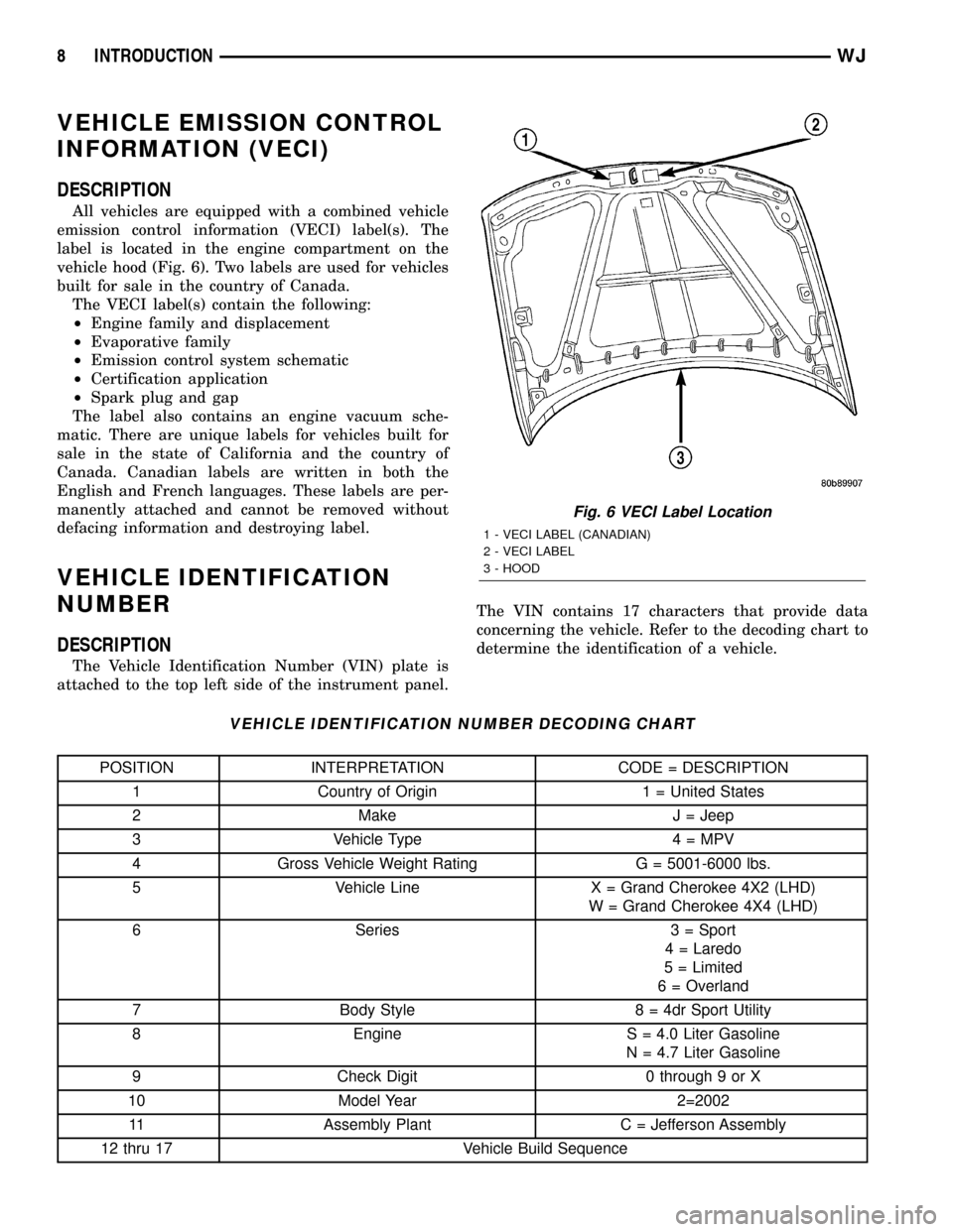
DESCRIPTION
All vehicles are equipped with a combined vehicle
emission control information (VECI) label(s). The
label is located in the engine compartment on the
vehicle hood (Fig. 6). Two labels are used for vehicles
built for sale in the country of Canada.
The VECI label(s) contain the following:
²Engine family and displacement
²Evaporative family
²Emission control system schematic
²Certification application
²Spark plug and gap
The label also contains an engine vacuum sche-
matic. There are unique labels for vehicles built for
sale in the state of California and the country of
Canada. Canadian labels are written in both the
English and French languages. These labels are per-
manently attached and cannot be removed without
defacing information and destroying label.
VEHICLE IDENTIFICATION
NUMBER
DESCRIPTION
The Vehicle Identification Number (VIN) plate is
attached to the top left side of the instrument panel.The VIN contains 17 characters that provide data
concerning the vehicle. Refer to the decoding chart to
determine the identification of a vehicle.
VEHICLE IDENTIFICATION NUMBER DECODING CHART
POSITION INTERPRETATION CODE = DESCRIPTION
1 Country of Origin 1 = United States
2 Make J = Jeep
3 Vehicle Type 4 = MPV
4 Gross Vehicle Weight Rating G = 5001-6000 lbs.
5 Vehicle Line X = Grand Cherokee 4X2 (LHD)
W = Grand Cherokee 4X4 (LHD)
6 Series 3 = Sport
4 = Laredo
5 = Limited
6 = Overland
7 Body Style 8 = 4dr Sport Utility
8 Engine S = 4.0 Liter Gasoline
N = 4.7 Liter Gasoline
9 Check Digit 0 through 9 or X
10 Model Year 2=2002
11 Assembly Plant C = Jefferson Assembly
12 thru 17 Vehicle Build Sequence
Fig. 6 VECI Label Location
1 - VECI LABEL (CANADIAN)
2 - VECI LABEL
3 - HOOD
8 INTRODUCTIONWJ
Page 27 of 2199

FRONT
TABLE OF CONTENTS
page page
FRONT
DESCRIPTION..........................6
STANDARD PROCEDURE - SERVICE
WARNINGS AND CAUTIONS..............6
SPECIFICATIONS
TORQUE CHART......................7
SPECIAL TOOLS
FRONT SUSPENSION...................8
BUSHINGS
REMOVAL.............................9
INSTALLATION..........................9
HUB / BEARING
DESCRIPTION..........................9
OPERATION............................9
REMOVAL.............................9
INSTALLATION.........................10
KNUCKLE
DESCRIPTION.........................10
OPERATION...........................10
REMOVAL - STEERING KNUCKLE..........10
INSTALLATION.........................10
LOWER BALL JOINT
REMOVAL.............................11
LOWER CONTROL ARM
DESCRIPTION.........................11
OPERATION...........................11
REMOVAL.............................11
INSTALLATION.........................11SHOCK
DESCRIPTION.........................12
OPERATION...........................12
REMOVAL.............................12
INSTALLATION.........................12
SPRING
DESCRIPTION.........................12
OPERATION...........................13
REMOVAL.............................13
INSTALLATION.........................13
STABILIZER BAR
DESCRIPTION.........................14
OPERATION...........................14
REMOVAL.............................14
INSTALLATION.........................14
TRACK BAR
DESCRIPTION.........................14
OPERATION...........................14
REMOVAL.............................14
INSTALLATION.........................14
UPPER BALL JOINT
REMOVAL.............................15
UPPER CONTROL ARM
DESCRIPTION.........................16
OPERATION...........................16
REMOVAL.............................16
INSTALLATION.........................16
FRONT
DESCRIPTION
The front suspension (Fig. 1) is a link/coil design
comprised of :
²Drive axle
²Shock absorbers
²Coil springs
²Upper and lower suspension arms
²Stabilizer bar
²Track bar
²Jounce bumpers
CAUTION: Components attached with a nut and cot-
ter pin must be torqued to specification. Then if the
slot in the nut does not line up with the cotter pin
hole, tighten nut until it is aligned. Never loosen the
nut to align the cotter pin hole.CAUTION: Suspension components with rubber
bushings must be tightened with the vehicle at nor-
mal ride height. It is important to have the springs
supporting the weight of the vehicle when the fas-
teners are torqued. If springs are not at their normal
ride position, vehicle ride comfort will be affected
and cause premature bushing wear.
STANDARD PROCEDURE - SERVICE
WARNINGS AND CAUTIONS
CAUTION: Suspension components with rubber
bushings must be tightened with the vehicle at nor-
mal ride height. It is important to have the springs
supporting the weight of the vehicle when the fas-
teners are torqued. If springs are not at their normal
ride position, vehicle ride comfort will be affected
and cause premature bushing wear.
2 - 6 FRONTWJ
Page 32 of 2199

LOWER BALL JOINT
REMOVAL
Ball stud service procedures below require removal
of the hub bearing and axle shaft. Removal and
installation of upper and lower ball studs require the
use of Tool Kit 6289.
(1) Position tools as shown to remove and install
ball stud (Fig. 6).
LOWER CONTROL ARM
DESCRIPTION
The lower suspension arms are hydroformed steel
and use voided oval bushings at one end of the arm.
OPERATION
The bushings provide isolation from the axle. The
arms mount to the unibody frame rail bracket and
the axle brackets. The arm and bushings provide
location and react to loads from the axle.
REMOVAL
(1) Raise the vehicle and support the front axle.
(2) Remove the lower suspension arm nut and bolt
from the axle bracket (Fig. 7).
(3) Remove the nut and bolt from the frame rail
bracket and remove the lower suspension arm (Fig.
7).
INSTALLATION
(1) Position the lower suspension arm in the axle
bracket and frame rail bracket.
NOTE: The end of the arm with the oval bushing
attaches to the axle bracket.
(2) Install the axle bracket bolt and nut finger
tight.
(3) Install the frame rail bracket bolt and nut fin-
ger tight.
(4) Remove support and lower the vehicle.
(5) With the vehicle on the ground tighten the
frame bracket bolt to 156 N´m (115 ft. lbs.). Tighten
the axle bracket nut to 163 N´m (120 ft. lbs.).
(6) Check the alignment if new parts were
installed.
Fig. 6 Lower
1 - SPECIAL TOOL 6289±12
2 - SPECIAL TOOL 6289±4
3 - SPECIAL TOOL 4212F
4 - SPECIAL TOOL 4212F5 - SPECIAL TOOL 6289±1
6 - SPECIAL TOOL 6289±3
WJFRONT 2 - 11
Page 33 of 2199

SHOCK
DESCRIPTION
The top of the shock absorbers are bolted to the
body. The bottom of the shocks are bolted to the axle
brackets. The standard shocks have conventional
twin tube construction and are low pressure gas
charged. Gas charging prevents cavitation during
rough road operation. Up-Country shocks are mono
tube design and are high pressure gas charged.
OPERATION
The shock absorbers dampen jounce and rebound
motion of the vehicle over various road conditions
and limit suspension rebound travel.
REMOVAL
(1) Remove the nut, retainer and grommet from
the shock stud in the engine compartment (Fig. 8).
(2) Raise and support the front axle.
(3) Remove the lower mounting nuts from the axle
bracket (Fig. 9). Remove the shock absorber.
INSTALLATION
(1) Position the lower retainer and grommet on the
shock stud. Insert the shock absorber through the
shock tower hole.
(2) Install the lower shock studs into the axle
bracket.
(3) Install the mounting nuts and tighten to 28
N´m (250 in. lbs.).
(4) Remove support and lower the vehicle.(5) Install the upper grommet, retainer and nut on
the stud in the engine compartment. Hold the shock
stud witha8mmwrench and tighten the nut to 35
N´m (26 ft. lbs.).SPRING
DESCRIPTION
The coil springs mount up in the wheelhouse which
is part of the unitized body bracket. A rubber dough-
nut isolator is located between the top of the spring
and the body. The bottom of the spring seats on a
axle isolator made of rubber with a steel insert.
Fig. 7 Lower Suspension Arm
1 - LOWER SUSPENSION ARM
2 - FRAME RAIL BRACKET
3 - AXLE BRACKET
Fig. 8 Upper Shock Mounting
1 - RETAINER
2 - STUD
3 - NUT
4 - GROMMET
Fig. 9 Lower Shock Mounting
1 - SHOCK ABSORBER
2 - MOUNTING NUTS
2 - 12 FRONTWJ
LOWER CONTROL ARM (Continued)
Page 34 of 2199

OPERATION
The coil springs control ride quality and maintain
proper ride height. The isolators provide road noise
isolation.
REMOVAL
(1) Raise and support the vehicle.
(2) Remove the wheel and tire assemblies.
(3) Position a hydraulic jack under the axle to sup-
port it.
(4) Remove shock absorbers lower mounting nuts
from the axle brackets.
(5) Remove the track bar mounting bolt from the
axle bracket.
NOTE: Make sure the lower part of the shock does
not hold tension on the brake lines at the axle tube
housing located at the lower shock mounting area.
(6) Lower the axle until the spring is free from the
upper mount and isolator (Fig. 10).
(7) Remove the spring from the vehicle.
(8) Remove and inspect the upper and lower
spring isolators.
INSTALLATION
(1) Install the upper isolator.
(2) Install the lower isolator with the isolator loca-
tor nub in the axle pad hole (Fig. 11).
(3) Position the coil spring on the axle spring pad.CAUTION: Ensure the spring is positioned on the
lower isolator with the end of the spring coil
against the isolator spring locator (Fig. 12).
(4) Raise the axle and guide the springs onto the
spring upper mounts and lower shock studs into the
axle brackets.
(5) Install the shock absorbers lower mounting
nuts.
Fig. 10 Front Coil Spring
1 - UPPER ISOLATOR
2 - COIL SPRING
3 - LOWER ISOLATOR
4 - STABILIZER LINK
Fig. 11 Lower Isolator
1 - LOCATING NUB
2 - LOWER ISOLATOR
3 - AXLE SPRING PAD
4 - LOCATING HOLE
Fig. 12 Isolator Spring Locator
1 - COIL SPRING
2 - SPRING LOCATOR
3 - LOWER ISOLATOR
WJFRONT 2 - 13
SPRING (Continued)