2002 JEEP GRAND CHEROKEE Control
[x] Cancel search: ControlPage 35 of 2199
(6) Install the track bar to the axle bracket and
install the mounting bolt.
NOTE: It may be necessary to pry the axle assem-
bly over to install the track bar bolt.
(7) Remove the hydraulic jack from under the
vehicle.
(8) Tighten all suspension components to proper
torque.
(9) Install the wheel and tire assemblies.
(10) Remove support and lower vehicle.
STABILIZER BAR
DESCRIPTION
The bar extends across the front underside of the
chassis and is mounted to the frame rails. Links are
connected from the bar to the axle brackets. The sta-
bilizer bar and links are isolated by rubber bushings.
OPERATION
The stabilizer bar is used to control vehicle body
roll during turns. The spring steel bar helps to con-
trol the vehicle body in relationship to the suspen-
sion.
REMOVAL
(1) Raise and support the vehicle.
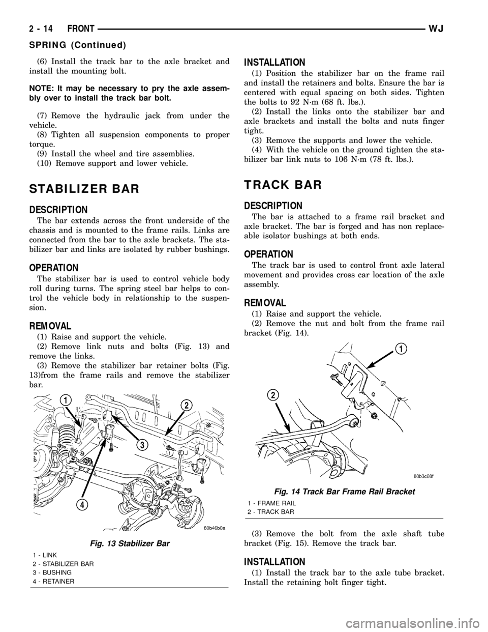
(2) Remove link nuts and bolts (Fig. 13) and
remove the links.
(3) Remove the stabilizer bar retainer bolts (Fig.
13)from the frame rails and remove the stabilizer
bar.
INSTALLATION
(1) Position the stabilizer bar on the frame rail
and install the retainers and bolts. Ensure the bar is
centered with equal spacing on both sides. Tighten
the bolts to 92 N´m (68 ft. lbs.).
(2) Install the links onto the stabilizer bar and
axle brackets and install the bolts and nuts finger
tight.
(3) Remove the supports and lower the vehicle.
(4) With the vehicle on the ground tighten the sta-
bilizer bar link nuts to 106 N´m (78 ft. lbs.).
TRACK BAR
DESCRIPTION
The bar is attached to a frame rail bracket and
axle bracket. The bar is forged and has non replace-
able isolator bushings at both ends.
OPERATION
The track bar is used to control front axle lateral
movement and provides cross car location of the axle
assembly.
REMOVAL
(1) Raise and support the vehicle.
(2) Remove the nut and bolt from the frame rail
bracket (Fig. 14).
(3) Remove the bolt from the axle shaft tube
bracket (Fig. 15). Remove the track bar.
INSTALLATION
(1) Install the track bar to the axle tube bracket.
Install the retaining bolt finger tight.
Fig. 13 Stabilizer Bar
1 - LINK
2 - STABILIZER BAR
3 - BUSHING
4 - RETAINER
Fig. 14 Track Bar Frame Rail Bracket
1 - FRAME RAIL
2 - TRACK BAR
2 - 14 FRONTWJ
SPRING (Continued)
Page 37 of 2199
UPPER CONTROL ARM
DESCRIPTION
The upper suspension arms are hydroformed steel
and use rubber bushings at each end of the arm.
OPERATION
The arms mount to the unibody frame rail bracket
and the axle brackets. The arm and bushings provide
location and react to loads from the axle. The bush-
ings provide isolation from the axle.
REMOVAL
(1) Raise vehicle and support the axle.
(2) Remove the upper suspension arm mounting
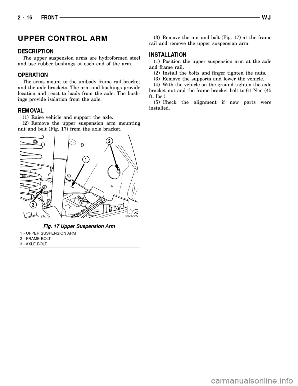
nut and bolt (Fig. 17) from the axle bracket.(3) Remove the nut and bolt (Fig. 17) at the frame
rail and remove the upper suspension arm.
INSTALLATION
(1) Position the upper suspension arm at the axle
and frame rail.
(2) Install the bolts and finger tighten the nuts.
(3) Remove the supports and lower the vehicle.
(4) With the vehicle on the ground tighten the axle
bracket nut and the frame bracket bolt to 61 N´m (45
ft. lbs.).
(5) Check the alignment if new parts were
installed.
Fig. 17 Upper Suspension Arm
1 - UPPER SUSPENSION ARM
2 - FRAME BOLT
3 - AXLE BOLT
2 - 16 FRONTWJ
Page 38 of 2199

REAR
TABLE OF CONTENTS
page page
REAR
DESCRIPTION.........................17
WARNING.............................17
DIAGNOSIS AND TESTING - REAR
SUSPENSION........................18
SPECIFICATIONS
TORQUE CHART......................18
SPECIAL TOOLS
REAR SUSPENSION...................19
LOWER CONTROL ARM
DESCRIPTION.........................19
OPERATION...........................19
REMOVAL.............................19
INSTALLATION.........................19
SHOCK
DESCRIPTION.........................19
OPERATION...........................19
REMOVAL.............................19
INSTALLATION.........................19
SPRING
DESCRIPTION.........................20OPERATION...........................20
REMOVAL.............................20
INSTALLATION.........................20
STABILIZER BAR
DESCRIPTION.........................21
OPERATION...........................21
REMOVAL.............................21
INSTALLATION.........................21
UPPER BALL JOINT
DESCRIPTION - UPPER SUSPENSION ARM,
BUSHINGS, AND BALL JOINT............21
OPERATION - UPPER SUSPENSION ARM,
BUSHINGS, AND BALL JOINT............21
REMOVAL.............................21
INSTALLATION.........................22
UPPER CONTROL ARM
DESCRIPTION.........................22
OPERATION...........................22
REMOVAL.............................22
INSTALLATION.........................23
REAR
DESCRIPTION
The rear suspension (Fig. 1) is comprised of :
²Drive axle
²Shock absorbers
²Coil springs
²Lower suspension arms
²Upper suspension arm
²Stabilizer bar
CAUTION: Suspension components with rubber/ure-
thane bushings should be tightened with the vehi-
cle at normal ride height. It is important to have the
springs supporting the weight of the vehicle when
the fasteners are torqued. This will maintain vehicle
ride comfort and prevent premature bushing wear.
WARNING
WARNING:: Suspension components with rubber
bushings must be tightened with the vehicle at nor-
mal ride height. It is important to have the springs
supporting the weight of the vehicle when the fas-
teners are torqued. If springs are not at their normalride position, vehicle ride comfort will be affected
and cause premature bushing wear.
Fig. 1 Rear Suspension
1 - SHOCK
2 - UPPER SUSPENSION ARM
3 - COIL SPRING
4 - STABILIZER BAR
5 - LOWER SUSPENSION ARM
WJREAR 2 - 17
Page 40 of 2199

SPECIAL TOOLS
REAR SUSPENSION
LOWER CONTROL ARM
DESCRIPTION
The lower suspension arms are hydroformed steel
and use voided oval bushings at each end of the arm.
OPERATION
The bushings provide isolation from the axle. The
arms mount to the unibody frame rail bracket and
the axle brackets. The arm and bushings provide
location and react to loads.
REMOVAL
(1) Raise the vehicle and support the rear axle.
(2) Remove the lower suspension arm nut and bolt
from the axle bracket (Fig. 2).
(3) Remove the nut and bolt (Fig. 2) from the
frame rail and remove the lower suspension arm.
INSTALLATION
(1) Position the lower suspension arm in the axle
bracket and frame rail bracket.
NOTE: The end of the arm with the oval bushing
attaches to the axle bracket.
(2) Install the axle bracket bolt and nut finger
tight.
(3) Install the frame rail bracket bolt and nut fin-
ger tight.
(4) Remove the supports and lower the vehicle.
(5) With the vehicle on the ground tighten the nut
at the frame to 156 N´m (115 ft. lbs.). Tighten the
nut at the axle bracket to 163 N´m (120 ft. lbs.).
SHOCK
DESCRIPTION
The top of the shock absorbers are bolted to the
body. The bottom of the shocks are bolted to the axle
brackets. The standard shocks have conventional
twin tube construction and are low pressure gas
charged. Gas charging prevents cavitation during
rough road operation. Up-Country shocks are mono
tube design and are high pressure gas charged.
OPERATION
The shock absorbers dampen jounce and rebound
motion of the vehicle over various road conditions
and limit suspension rebound travel.
REMOVAL
(1) Raise and support the vehicle. Position a
hydraulic jack under the axle to support the axle.
CAUTION: Do not allow the axle to hang from the
upper suspension arm ball joint.
(2) Remove the upper nut and bolt from the frame
bracket (Fig. 3).
(3) Remove the lower nut and bolt from the axle
bracket. Remove the shock absorber.
INSTALLATION
(1) Install the shock absorber in the frame bracket
and install the bolt and nut.
(2) Install the shock absorber in the axle bracket
and install the bolt and nut.
(3) Tighten the upper mounting nuts to 108 N´m
(80 ft. lbs.). Tighten the lower mounting nuts to 115
N´m (85 ft. lbs.).
(4) Remove the supports and lower the vehicle.
Remover 8278
Fig. 2 Lower Suspension Arm
1 - LOWER SUSPENSION ARM
2 - AXLE BRACKET
3 - FRAME BRACKET
WJREAR 2 - 19
REAR (Continued)
Page 41 of 2199
SPRING
DESCRIPTION
The coil springs mount up in the wheelhouse which
is part of the unitized body bracket. A rubber dough-
nut isolator is located between the top of the spring
and the body. The bottom of the spring seats on a
axle isolator made of rubber with a steel insert. The
isolators provide road noise isolation
OPERATION
The coil springs control ride quality and maintain
proper ride height.
REMOVAL
(1) Raise and support the vehicle. Position a
hydraulic jack under the axle to support the axle.
(2) Remove the wheel and tire assemblies.
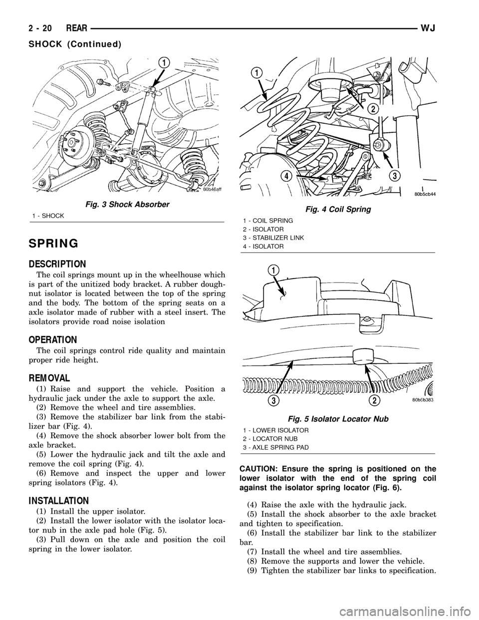
(3) Remove the stabilizer bar link from the stabi-
lizer bar (Fig. 4).
(4) Remove the shock absorber lower bolt from the
axle bracket.
(5) Lower the hydraulic jack and tilt the axle and
remove the coil spring (Fig. 4).
(6) Remove and inspect the upper and lower
spring isolators (Fig. 4).
INSTALLATION
(1) Install the upper isolator.
(2) Install the lower isolator with the isolator loca-
tor nub in the axle pad hole (Fig. 5).
(3) Pull down on the axle and position the coil
spring in the lower isolator.CAUTION: Ensure the spring is positioned on the
lower isolator with the end of the spring coil
against the isolator spring locator (Fig. 6).
(4) Raise the axle with the hydraulic jack.
(5) Install the shock absorber to the axle bracket
and tighten to specification.
(6) Install the stabilizer bar link to the stabilizer
bar.
(7) Install the wheel and tire assemblies.
(8) Remove the supports and lower the vehicle.
(9) Tighten the stabilizer bar links to specification.
Fig. 3 Shock Absorber
1 - SHOCKFig. 4 Coil Spring
1 - COIL SPRING
2 - ISOLATOR
3 - STABILIZER LINK
4 - ISOLATOR
Fig. 5 Isolator Locator Nub
1 - LOWER ISOLATOR
2 - LOCATOR NUB
3 - AXLE SPRING PAD
2 - 20 REARWJ
SHOCK (Continued)
Page 42 of 2199

STABILIZER BAR
DESCRIPTION
The stabilizer bar extends across the back side of
the rear axle. Links are connected between the bar
and frame rail brackets. The stabilizer bar and links
are isolated by rubber bushings.
OPERATION
The stabilizer bar is used to control vehicle body
roll, during turns. The bar helps control the vehicle
body in relationship to the suspension.
REMOVAL
(1) Raise and support the vehicle.
(2) Remove the stabilizer bar links from stabilizer
bar and frame mount. (Fig. 7).
(3) Remove the stabilizer bar retainer bolts.
(4) Remove the stabilizer bar.
INSTALLATION
(1) Position the stabilizer bar on the axle and
install the retainers and bolts. Ensure the bar is cen-
tered with equal spacing on both sides. Tighten the
bolts to 54 N´m (40 ft. lbs.).
(2) Install the links to the stabilizer bar and frame
brackets.
(3) Tighten the nuts at the stabilizer bar to 54
N´m (40 ft. lbs.).
(4) Tighten the nuts at the frame brackets to 92
N´m (68 ft. lbs.).
(5) Remove support and lower the vehicle.
UPPER BALL JOINT
DESCRIPTION - UPPER SUSPENSION ARM,
BUSHINGS, AND BALL JOINT
The suspension arm uses vertical spool bushings to
isolate road noise. The suspension arm is bolted
through bushings to cage nuts in the body and a ball
joint plate to the top of the differential housing.
OPERATION - UPPER SUSPENSION ARM,
BUSHINGS, AND BALL JOINT
The upper suspension arm provides fore/aft and
lateral location of the rear axle. The suspension arm
travel is limited through the use of jounce bumpers
in compression and shock absorbers in rebound.
REMOVAL
(1) Raise and support the vehicle.
(2) Support the rear axle with a hydraulic jack.
(3) Remove the ball joint nut from the top of the
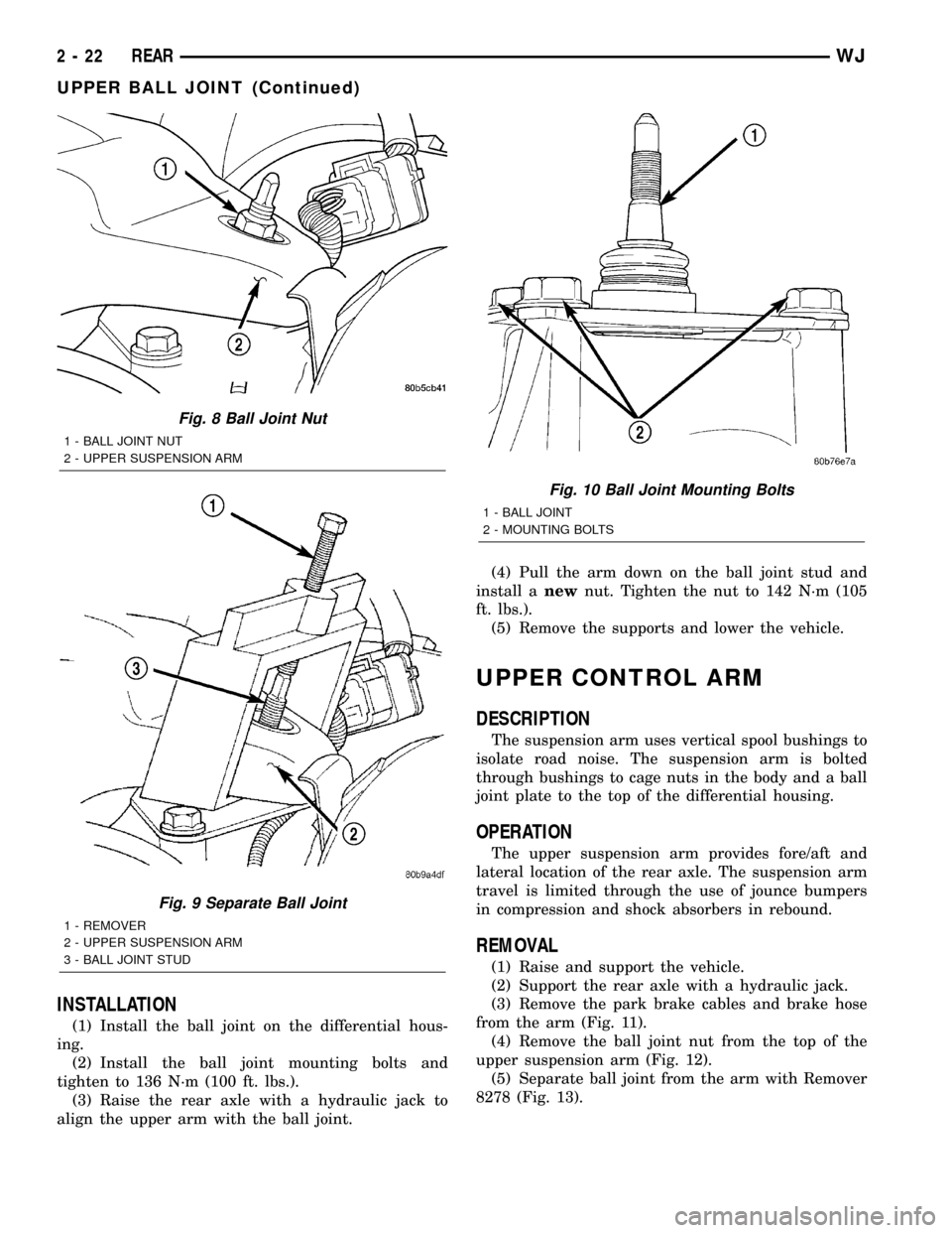
upper suspension arm (Fig. 8).
(4) Separate ball joint from the arm with Remover
8278 (Fig. 9).
NOTE: It may be necessary to strike the upper con-
trol arm with a hammer to separate the ball joint
from the arm.
(5) Remove the ball joint mounting bolts (Fig.
10)from the differential housing.
(6) Remove the ball joint from the differential
housing.
Fig. 6 Isolator Spring Locator - Typical
1 - LOWER ISOLATOR
2 - SPRING LOCATOR
3 - COIL SPRING
Fig. 7 Rear Stabilizer Bar
1 - LINK
2 - RETAINER
3 - BUSHING
4 - STABILIZER BAR
WJREAR 2 - 21
SPRING (Continued)
Page 43 of 2199
INSTALLATION
(1) Install the ball joint on the differential hous-
ing.
(2) Install the ball joint mounting bolts and
tighten to 136 N´m (100 ft. lbs.).
(3) Raise the rear axle with a hydraulic jack to
align the upper arm with the ball joint.(4) Pull the arm down on the ball joint stud and
install anewnut. Tighten the nut to 142 N´m (105
ft. lbs.).
(5) Remove the supports and lower the vehicle.
UPPER CONTROL ARM
DESCRIPTION
The suspension arm uses vertical spool bushings to
isolate road noise. The suspension arm is bolted
through bushings to cage nuts in the body and a ball
joint plate to the top of the differential housing.
OPERATION
The upper suspension arm provides fore/aft and
lateral location of the rear axle. The suspension arm
travel is limited through the use of jounce bumpers
in compression and shock absorbers in rebound.
REMOVAL
(1) Raise and support the vehicle.
(2) Support the rear axle with a hydraulic jack.
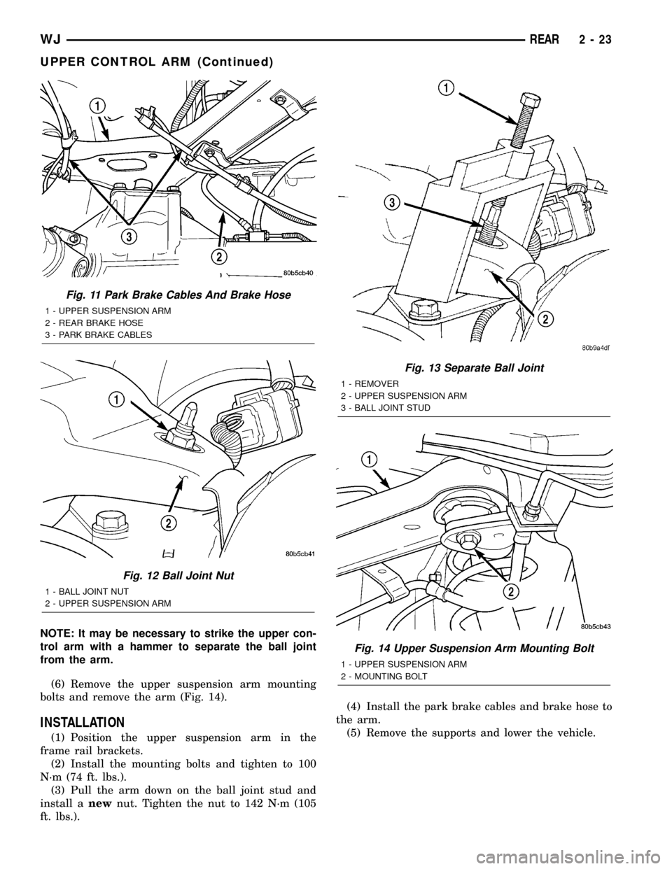
(3) Remove the park brake cables and brake hose
from the arm (Fig. 11).
(4) Remove the ball joint nut from the top of the
upper suspension arm (Fig. 12).
(5) Separate ball joint from the arm with Remover
8278 (Fig. 13).
Fig. 8 Ball Joint Nut
1 - BALL JOINT NUT
2 - UPPER SUSPENSION ARM
Fig. 9 Separate Ball Joint
1 - REMOVER
2 - UPPER SUSPENSION ARM
3 - BALL JOINT STUD
Fig. 10 Ball Joint Mounting Bolts
1 - BALL JOINT
2 - MOUNTING BOLTS
2 - 22 REARWJ
UPPER BALL JOINT (Continued)
Page 44 of 2199
NOTE: It may be necessary to strike the upper con-
trol arm with a hammer to separate the ball joint
from the arm.
(6) Remove the upper suspension arm mounting
bolts and remove the arm (Fig. 14).
INSTALLATION
(1) Position the upper suspension arm in the
frame rail brackets.
(2) Install the mounting bolts and tighten to 100
N´m (74 ft. lbs.).
(3) Pull the arm down on the ball joint stud and
install anewnut. Tighten the nut to 142 N´m (105
ft. lbs.).(4) Install the park brake cables and brake hose to
the arm.
(5) Remove the supports and lower the vehicle.
Fig. 11 Park Brake Cables And Brake Hose
1 - UPPER SUSPENSION ARM
2 - REAR BRAKE HOSE
3 - PARK BRAKE CABLES
Fig. 12 Ball Joint Nut
1 - BALL JOINT NUT
2 - UPPER SUSPENSION ARM
Fig. 13 Separate Ball Joint
1 - REMOVER
2 - UPPER SUSPENSION ARM
3 - BALL JOINT STUD
Fig. 14 Upper Suspension Arm Mounting Bolt
1 - UPPER SUSPENSION ARM
2 - MOUNTING BOLT
WJREAR 2 - 23
UPPER CONTROL ARM (Continued)