2002 JEEP GRAND CHEROKEE torque specifications
[x] Cancel search: torque specificationsPage 1495 of 2199
ADJUSTMENTS
STEERING GEAR
NOTE: Adjusting the steering gear in the vehicle is
not recommended. Remove gear from the vehicle
and drain the fluid. Then mount gear in a vise to
perform adjustments.
OVER-CENTER
(1) Rotate the stub shaft with Socket 8343 from
stop to stop and count the number of turns.
(2) Center the stub shaft by rotating it from the
stop 1/2 of the total amount of turns.
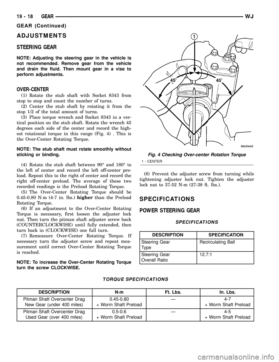
(3) Place torque wrench and Socket 8343 in a ver-
tical position on the stub shaft. Rotate the wrench 45
degrees each side of the center and record the high-
est rotational torque in this range (Fig. 4) . This is
the Over-Center Rotating Torque.
NOTE: The stub shaft must rotate smoothly without
sticking or binding.
(4) Rotate the stub shaft between 90É and 180É to
the left of center and record the left off-center pre-
load. Repeat this to the right of center and record the
right off-center preload. The average of these two
recorded readings is the Preload Rotating Torque.
(5) The Over-Center Rotating Torque should be
0.45-0.80 N´m (4-7 in. lbs.)higherthan the Preload
Rotating Torque.
(6) If an adjustment to the Over-Center Rotating
Torque is necessary, first loosen the adjuster lock
nut. Then turn the pitman shaft adjuster screw back
(COUNTERCLOCKWISE) until fully extended, then
turn back in (CLOCKWISE) one full turn.
(7) Remeasure Over-Center Rotating Torque. If
necessary turn the adjuster screw and repeat mea-
surement until correct Over-Center Rotating Torque
is reached.
NOTE: To increase the Over-Center Rotating Torque
turn the screw CLOCKWISE.(8) Prevent the adjuster screw from turning while
tightening adjuster lock nut. Tighten the adjuster
lock nut to 37-52 N´m (27-38 ft. lbs.).
SPECIFICATIONS
POWER STEERING GEAR
SPECIFICATIONS
DESCRIPTION SPECIFICATION
Steering Gear
TypeRecirculating Ball
Steering Gear
Overall Ratio12.7:1
TORQUE SPECIFICATIONS
DESCRIPTION N´m Ft. Lbs. In. Lbs.
Pitman Shaft Overcenter Drag
New Gear (under 400 miles)0.45-0.80
+ Worm Shaft PreloadÐ 4-7
+ Worm Shaft Preload
Pitman Shaft Overcenter Drag
Used Gear (over 400 miles)0.5-0.6
+ Worm Shaft PreloadÐ 4-5
+ Worm Shaft Preload
Fig. 4 Checking Over-center Rotation Torque
1 - CENTER
19 - 18 GEARWJ
GEAR (Continued)
Page 1503 of 2199

LINKAGE
TABLE OF CONTENTS
page page
LINKAGE
DESCRIPTION
STEERING LINKAGE ± RIGHT HAND DRIVE
(RHD) VEHICLES......................26
DESCRIPTION........................26
SPECIFICATIONS
TORQUE CHART......................28
SPECIAL TOOLS
STEERING LINKAGE...................28
DAMPER
DESCRIPTION.........................28
OPERATION...........................28
REMOVAL.............................28
INSTALLATION.........................29
DRAG LINK
DESCRIPTION.........................29OPERATION...........................29
REMOVAL.............................29
INSTALLATION.........................29
PITMAN ARM
DESCRIPTION.........................29
OPERATION...........................29
REMOVAL.............................29
INSTALLATION.........................30
TIE ROD END
DESCRIPTION.........................30
OPERATION...........................30
REMOVAL.............................30
INSTALLATION.........................30
LINKAGE
DESCRIPTION
STEERING LINKAGE ± RIGHT HAND DRIVE
(RHD) VEHICLES
Vehicles equipped with right hand drive (RHD)
steering utilize the same components of left hand
drive vehicles. The RHD Steering linkage is designed
as a mirror image of left hand drive linkage with the
exception of the steering damper (Fig. 1), which is
mounted on the same side of the vehicle weather
RHD or LHD. See figure below for reference. All
specifications are the same as LHD. Refer to Group
19, Steering of the gasoline engine service manual for
additional information.
DESCRIPTION
The steering linkage consists of a pitman arm,
drag link, tie rod, and steering dampener (Fig. 2) .
An adjustment sleeve on the tie rod is used to set
wheel toe position. The sleeve on the drag link is
used for steering wheel centering.
CAUTION: If any steering components are replaced
or serviced an alignment must be performed, to
ensure the vehicle meets all alignment specifica-
tions.
CAUTION: Components attached with a nut and cot-
ter pin must be torqued to specification. Then if the
slot in the nut does not line up with the cotter pin
hole, tighten nut until it is aligned. Never loosen the
nut to align the cotter pin hole.
19 - 26 LINKAGEWJ
Page 1505 of 2199
SPECIFICATIONS
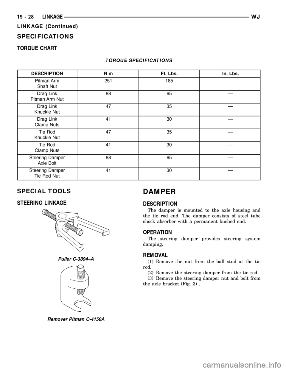
TORQUE CHART
TORQUE SPECIFICATIONS
DESCRIPTION N´m Ft. Lbs. In. Lbs.
Pitman Arm
Shaft Nut251 185 Ð
Drag Link
Pitman Arm Nut88 65 Ð
Drag Link
Knuckle Nut47 35 Ð
Drag Link
Clamp Nuts41 30 Ð
Tie Rod
Knuckle Nut47 35 Ð
Tie Rod
Clamp Nuts41 30 Ð
Steering Damper
Axle Bolt88 65 Ð
Steering Damper
Tie Rod Nut41 30 Ð
SPECIAL TOOLS
STEERING LINKAGEDAMPER
DESCRIPTION
The damper is mounted to the axle housing and
the tie rod end. The damper consists of steel tube
shock absorber with a permanent bushed end.
OPERATION
The steering damper provides steering system
damping.
REMOVAL
(1) Remove the nut from the ball stud at the tie
rod.
(2) Remove the steering damper from the tie rod.
(3) Remove the steering damper nut and bolt from
the axle bracket (Fig. 3) .Puller C-3894±A
Remover Pitman C-4150A
19 - 28 LINKAGEWJ
LINKAGE (Continued)
Page 1508 of 2199

PUMP
TABLE OF CONTENTS
page page
PUMP
DESCRIPTION - 4.0L, 4.7L................32
OPERATION
OPERATION - 4.7L....................32
OPERATION - 4.0L....................32
DIAGNOSIS AND TESTING - PUMP LEAKAGE . 33
STANDARD PROCEDURE
STANDARD PROCEDURE - INITIAL
OPERATION - 4.0L....................33
STANDARD PROCEDURE - INITIAL
OPERATION - 4.7L....................33
REMOVAL
REMOVAL - 4.0L ENGINE...............34
REMOVAL - 4.7L ENGINE...............34
INSTALLATION
INSTALLATION - 4.0L ENGINE...........34
INSTALLATION - 4.7L ENGINE...........34
SPECIFICATIONS
TORQUE CHART......................35
SPECIAL TOOLS
POWER STEERING PUMP..............36
FLUID COOLER
DESCRIPTION.........................36
REMOVAL.............................36
INSTALLATION.........................37
HOSES - 4.0L
DESCRIPTION
DESCRIPTION - PRESSURE LINE........37
DESCRIPTION - RETURN LINE...........37
OPERATION
OPERATION - PRESSURE LINE..........37
OPERATION - RETURN LINE............37
REMOVAL.............................37
INSTALLATION.........................37
HOSES - 4.7L
DESCRIPTION
DESCRIPTION - 1/2º PRESSURE HOSE....38DESCRIPTION - 1/2º RETURN HOSE......38
DESCRIPTION - 3/8º PRESSURE HOSE....38
DESCRIPTION - 3/8º GEAR OUTLET HOSE . 38
DESCRIPTION - 3/8º RETURN HOSE......38
OPERATION
OPERATION - 1/2º PRESSURE HOSE......38
OPERATION - 1/2º RETURN HOSE........38
OPERATION - 3/8º PRESSURE HOSE......39
OPERATION - 3/8º GEAR OUTLET HOSE . . . 39
OPERATION - 3/8ºRETURN HOSE........39
REMOVAL
REMOVAL - 1/29PRESSURE HOSE.......39
REMOVAL - 1/29RETURN HOSE..........39
REMOVAL - 3/89PRESSURE HOSE.......39
REMOVAL - 3/89RETURN HOSE..........39
REMOVAL - 3/89GEAR OUTLET HOSE.....40
REMOVAL - INLET COOLER HOSE........40
REMOVAL - OUTLET COOLER HOSE......40
INSTALLATION
INSTALLATION - 1/29PRESSURE HOSE....40
INSTALLATION - 1/29RETURN HOSE......40
INSTALLATION - 3/89PRESSURE HOSE....41
INSTALLATION - 3/89RETURN HOSE......41
INSTALLATION - 3/89GEAR OUTLET HOSE . 41
INSTALLATION - INLET COOLER HOSE....41
INSTALLATION - OUTLET COOLER HOSE . . 41
PULLEY
DESCRIPTION
POWER STEERING PUMP PULLEY - 3.1L
DIESEL.............................41
REMOVAL.............................41
INSTALLATION.........................42
RESERVOIR
REMOVAL.............................42
INSTALLATION.........................42
WJPUMP 19 - 31
Page 1512 of 2199
SPECIFICATIONS
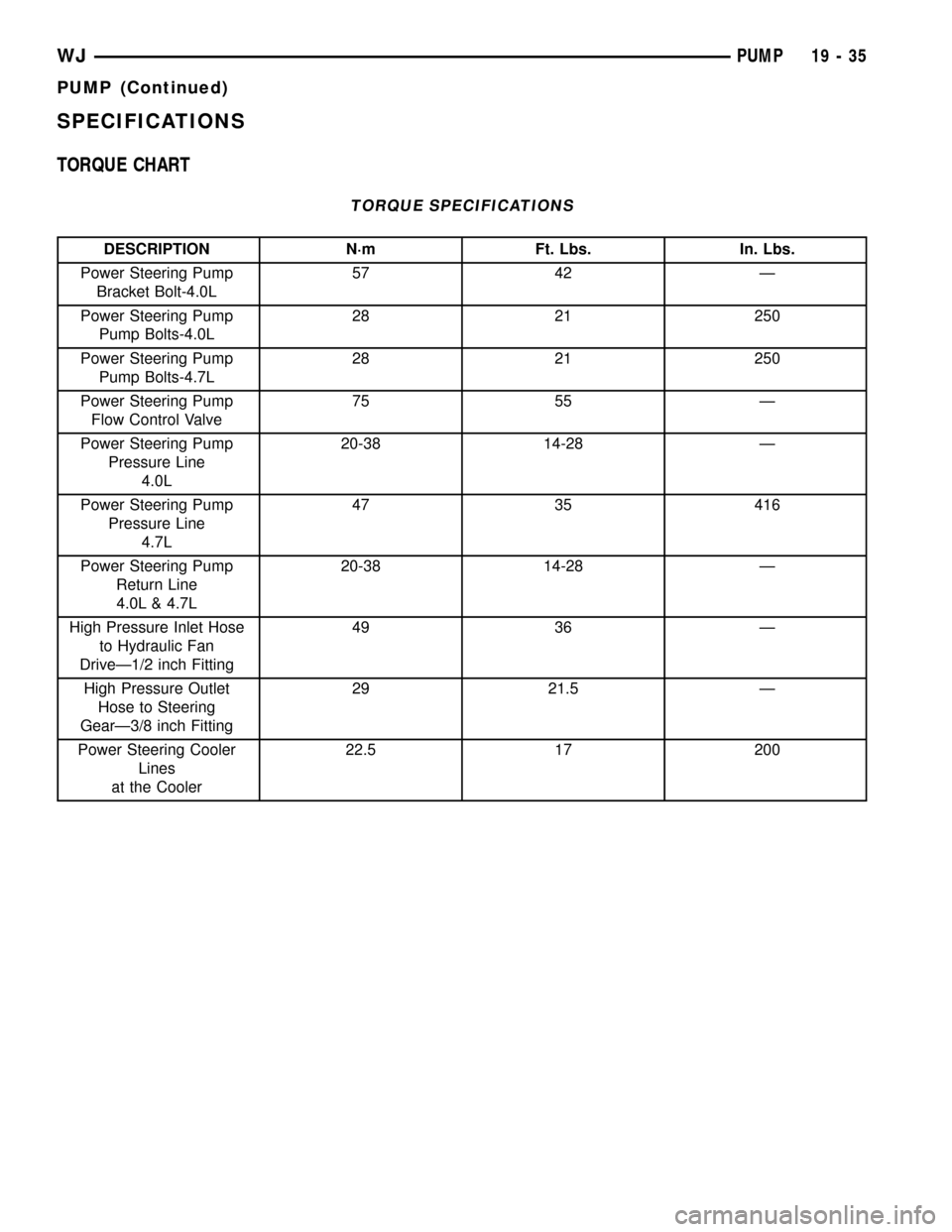
TORQUE CHART
TORQUE SPECIFICATIONS
DESCRIPTION N´m Ft. Lbs. In. Lbs.
Power Steering Pump
Bracket Bolt-4.0L57 42 Ð
Power Steering Pump
Pump Bolts-4.0L28 21 250
Power Steering Pump
Pump Bolts-4.7L28 21 250
Power Steering Pump
Flow Control Valve75 55 Ð
Power Steering Pump
Pressure Line
4.0L20-38 14-28 Ð
Power Steering Pump
Pressure Line
4.7L47 35 416
Power Steering Pump
Return Line
4.0L & 4.7L20-38 14-28 Ð
High Pressure Inlet Hose
to Hydraulic Fan
DriveÐ1/2 inch Fitting49 36 Ð
High Pressure Outlet
Hose to Steering
GearÐ3/8 inch Fitting29 21.5 Ð
Power Steering Cooler
Lines
at the Cooler22.5 17 200
WJPUMP 19 - 35
PUMP (Continued)
Page 1575 of 2199
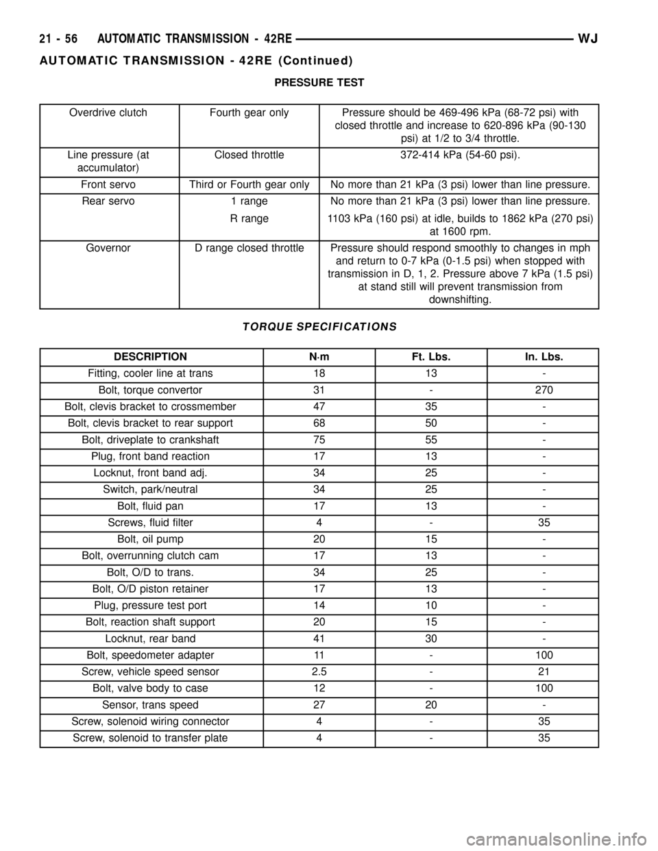
PRESSURE TEST
Overdrive clutch Fourth gear only Pressure should be 469-496 kPa (68-72 psi) with
closed throttle and increase to 620-896 kPa (90-130
psi) at 1/2 to 3/4 throttle.
Line pressure (at
accumulator)Closed throttle 372-414 kPa (54-60 psi).
Front servo Third or Fourth gear only No more than 21 kPa (3 psi) lower than line pressure.
Rear servo 1 range No more than 21 kPa (3 psi) lower than line pressure.
R range 1103 kPa (160 psi) at idle, builds to 1862 kPa (270 psi)
at 1600 rpm.
Governor D range closed throttle Pressure should respond smoothly to changes in mph
and return to 0-7 kPa (0-1.5 psi) when stopped with
transmission in D, 1, 2. Pressure above 7 kPa (1.5 psi)
at stand still will prevent transmission from
downshifting.
TORQUE SPECIFICATIONS
DESCRIPTION N´m Ft. Lbs. In. Lbs.
Fitting, cooler line at trans 18 13 -
Bolt, torque convertor 31 - 270
Bolt, clevis bracket to crossmember 47 35 -
Bolt, clevis bracket to rear support 68 50 -
Bolt, driveplate to crankshaft 75 55 -
Plug, front band reaction 17 13 -
Locknut, front band adj. 34 25 -
Switch, park/neutral 34 25 -
Bolt, fluid pan 17 13 -
Screws, fluid filter 4 - 35
Bolt, oil pump 20 15 -
Bolt, overrunning clutch cam 17 13 -
Bolt, O/D to trans. 34 25 -
Bolt, O/D piston retainer 17 13 -
Plug, pressure test port 14 10 -
Bolt, reaction shaft support 20 15 -
Locknut, rear band 41 30 -
Bolt, speedometer adapter 11 - 100
Screw, vehicle speed sensor 2.5 - 21
Bolt, valve body to case 12 - 100
Sensor, trans speed 27 20 -
Screw, solenoid wiring connector 4 - 35
Screw, solenoid to transfer plate 4 - 35
21 - 56 AUTOMATIC TRANSMISSION - 42REWJ
AUTOMATIC TRANSMISSION - 42RE (Continued)
Page 1739 of 2199
SPECIFICATIONS
TRANSMISSION
GENERAL
Component Metric Inch
Output Shaft End Play 0.22-0.55
mm0.009-0.021
in.
Input Shaft End Play 0.46-0.89
mm0.018-0.035
in.
2C Clutch Pack
Clearance0.455-1.335
mm0.018-0.053
in.
4C Clutch Pack
Clearance0.770-1.390
mm0.030-0.055
in.
L/R Clutch Pack
Clearance1.00-1.74
mm0.039-0.069
in.
OD Clutch Pack
Clearance1.103-1.856
mm0.043-0.073
in.
Component Metric Inch
UD Clutch Pack
Clearance0.84-1.54
mm0.033-0.061
in.
Reverse Clutch Pack
Clearance0.81-1.24
mm0.032-0.049
in.
Recommended fluid MoparTATF +4, type 9602
GEAR RATIOS
1ST 3.00:1
2ND 1.67:1
2ND Prime 1.50:1
3RD 1.0:1
4TH 0.75:1
5TH 0.67:1
REVERSE 3.00:1
TORQUE SPECIFICATIONS
DESCRIPTION N´m Ft. Lbs. In. Lbs.
Fitting, cooler line at trans 17.5 - 155
Bolt, torque convertor 31 23 -
Bolt/nut, crossmember 68 50 -
Bolt, driveplate to crankshaft 75 55 -
Bolt, oil pan 11.8 - 105
Screw, primary fluid filter 4.5 - 40
Bolt, oil pump 28.2 - 250
Bolt, oil pump body to cover 4.5 - 40
Screw, plate to oil pump body 4.5 - 40
Bolt, valve body to case 11.8 - 105
Plug, pressure test port 5.1 - 45
Bolt, reaction shaft support 11.8 - 105
Screw, valve body to transfer plate 5.6 - 50
Screw, solenoid module to transfer plate 5.7 - 50
Screw, accumulator cover 4.5 - 40
Screw, detent spring 4.5 - 40
Bolt, input speed sensor 11.8 - 105
Bolt, output speed sensor 11.8 - 105
Bolt, line pressure sensor 11.8 - 105
Bolt, extension housing 54 40 -
Valve, cooler return filter bypass 4.5 - 40
Screw, manual valve cam retaining 4.5 - 40
Bolt, manual lever 28.2 - 250
21 - 220 AUTOMATIC TRANSMISSION - 545RFEWJ
AUTOMATIC TRANSMISSION - 545RFE (Continued)
Page 1799 of 2199

TRANSFER CASE - NV242
TABLE OF CONTENTS
page page
TRANSFER CASE - NV242
DESCRIPTION........................280
OPERATION..........................281
DIAGNOSIS AND TESTING - TRANSFER
CASE - NV242.......................281
REMOVAL............................282
DISASSEMBLY........................282
CLEANING...........................292
INSPECTION.........................293
ASSEMBLY...........................295
INSTALLATION........................307
SPECIFICATIONS
TRANSFER CASE - NV242.............308
SPECIAL TOOLS
TRANSFER CASE - NV242.............308
FLUID
STANDARD PROCEDURE - FLUID DRAIN/
REFILL............................310FRONT OUTPUT SHAFT SEAL
REMOVAL............................310
INSTALLATION........................310
POSITION SENSOR
DESCRIPTION........................311
OPERATION..........................311
REMOVAL............................312
INSTALLATION........................312
REAR RETAINER BUSHING AND SEAL -
NV242HD
REMOVAL............................312
INSTALLATION........................312
SHIFT CABLE
REMOVAL............................313
INSTALLATION........................313
TRANSFER CASE - NV242
DESCRIPTION
The NV242 is a full transfer case (Fig. 1). It pro-
vides full time 2-wheel, or 4-wheel drive operation.
A differential in the transfer case is used to control
torque transfer to the front and rear axles. A low
range gear provides increased low speed torque capa-
bility for off road operation. The low range provides a
2.72:1 reduction ratio.
The geartrain is mounted in two aluminum case
halves attached with bolts. The mainshaft front and
rear bearings are mounted in aluminum retainer
housings bolted to the case halves.
TRANSFER CASE IDENTIFICATION
Two versions of the NV242 are used in the WJ
vehicles, NV242LD and NV242HD. The two transfer
cases can be distinguished from one another by the
rear output shaft retainer. The NV242LD uses a rub-
ber boot to cover the rear output shaft, while the
NV242HD uses a cast aluminum housing. Other than
this difference, the two transfer cases are serviced
the same.
A circular ID tag is attached to the rear case of
each transfer case (Fig. 2). The ID tag provides the
transfer case model number, assembly number, serial
number, and low range ratio.The transfer case serial number also represents
the date of build.
SHIFT MECHANISM
Operating ranges are selected with a lever in the
floor mounted shifter assembly. The shift lever is con-
nected to the transfer case range lever by an adjust-
able cable. A straight line shift pattern is used.
Range positions are marked on the shifter bezel.
Fig. 1 NV242 Transfer Case
21 - 280 TRANSFER CASE - NV242WJ