2002 JEEP GRAND CHEROKEE Power
[x] Cancel search: PowerPage 1 of 2199

GROUP TAB LOCATOR
Introduction
0Lubrication & Maintenance
2Suspension
3Driveline
5Brakes
7Cooling
8AAudio
8BChime/Buzzer
8EElectronic Control Modules
8FEngine Systems
8GHeated Systems
8HHorn
8IIgnition Control
8JInstrument Cluster
8LLamps
8MMessage Systems
8NPower Systems
8ORestraints
8PSpeed Control
8QVehicle Theft Security
8RWipers/Washers
8WWiring
9Engine
11Exhaust System
13Frame & Bumpers
14Fuel System
19Steering
21Transaxle
22Tires/Wheels
23Body
24Heating & Air Conditioning
25Emissions Control
Service Manual Comment Forms (Rear of Manual)
Page 22 of 2199

SUSPENSION
TABLE OF CONTENTS
page page
SUSPENSION
DIAGNOSIS AND TESTING - SUSPENSION
AND STEERING SYSTEM................1WHEEL ALIGNMENT......................3
FRONT.................................6
REAR.................................17
SUSPENSION
DIAGNOSIS AND TESTING - SUSPENSION AND
STEERING SYSTEM
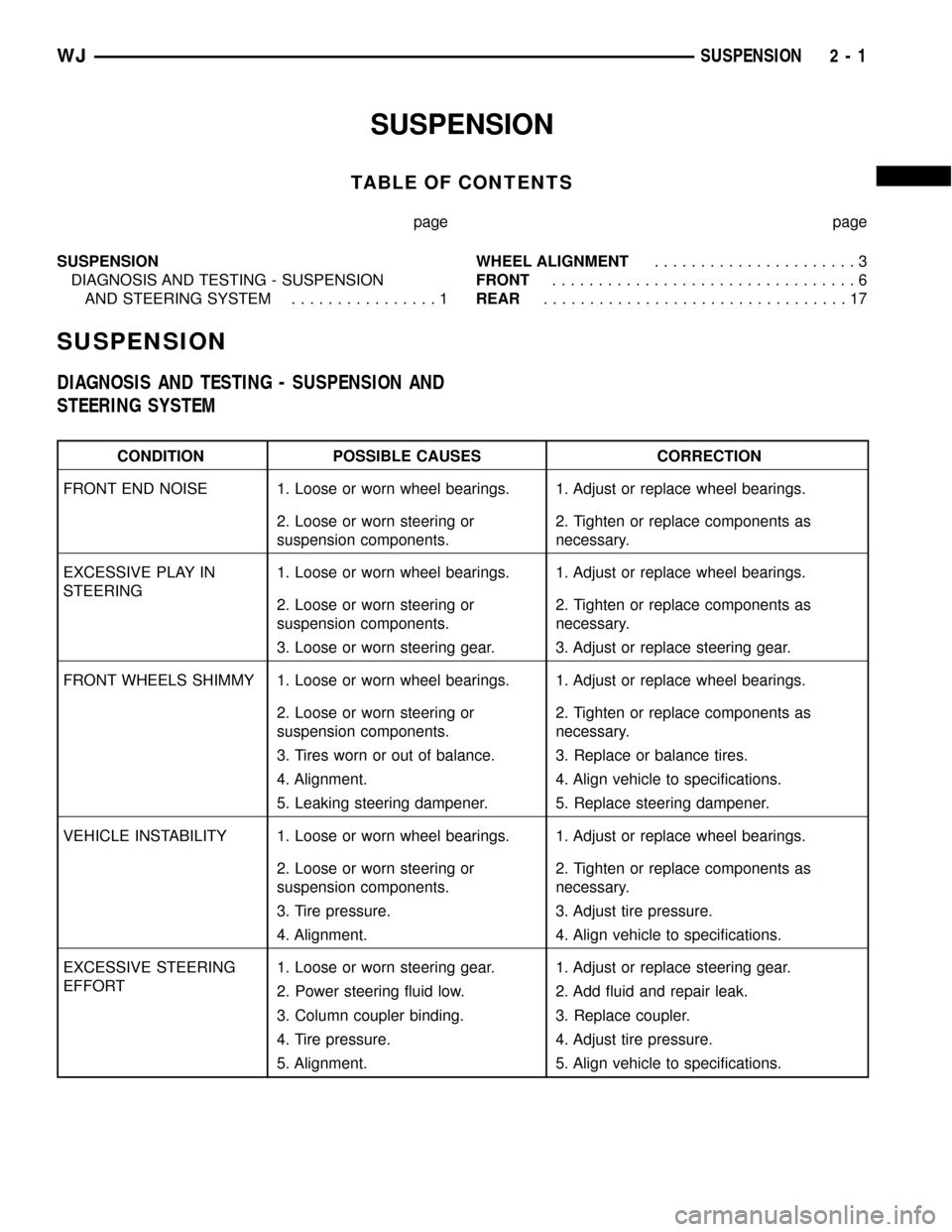
CONDITION POSSIBLE CAUSES CORRECTION
FRONT END NOISE 1. Loose or worn wheel bearings. 1. Adjust or replace wheel bearings.
2. Loose or worn steering or
suspension components.2. Tighten or replace components as
necessary.
EXCESSIVE PLAY IN
STEERING1. Loose or worn wheel bearings. 1. Adjust or replace wheel bearings.
2. Loose or worn steering or
suspension components.2. Tighten or replace components as
necessary.
3. Loose or worn steering gear. 3. Adjust or replace steering gear.
FRONT WHEELS SHIMMY 1. Loose or worn wheel bearings. 1. Adjust or replace wheel bearings.
2. Loose or worn steering or
suspension components.2. Tighten or replace components as
necessary.
3. Tires worn or out of balance. 3. Replace or balance tires.
4. Alignment. 4. Align vehicle to specifications.
5. Leaking steering dampener. 5. Replace steering dampener.
VEHICLE INSTABILITY 1. Loose or worn wheel bearings. 1. Adjust or replace wheel bearings.
2. Loose or worn steering or
suspension components.2. Tighten or replace components as
necessary.
3. Tire pressure. 3. Adjust tire pressure.
4. Alignment. 4. Align vehicle to specifications.
EXCESSIVE STEERING
EFFORT1. Loose or worn steering gear. 1. Adjust or replace steering gear.
2. Power steering fluid low. 2. Add fluid and repair leak.
3. Column coupler binding. 3. Replace coupler.
4. Tire pressure. 4. Adjust tire pressure.
5. Alignment. 5. Align vehicle to specifications.
WJSUSPENSION 2 - 1
Page 60 of 2199

FRONT AXLE - 186FBI
TABLE OF CONTENTS
page page
FRONT AXLE - 186FBI
DESCRIPTION.........................15
OPERATION...........................15
DIAGNOSIS AND TESTING................16
REMOVAL.............................20
INSTALLATION.........................21
ADJUSTMENTS........................21
SPECIFICATIONS.......................30
SPECIAL TOOLS.......................31
AXLE SHAFTS
REMOVAL.............................34
INSTALLATION.........................34
AXLE SHAFT SEALS
REMOVAL.............................35
INSTALLATION.........................35
AXLE - C/V JOINT
REMOVAL.............................35
INSTALLATION.........................35
AXLE - U-JOINT
REMOVAL.............................36INSTALLATION.........................37
PINION SEAL
REMOVAL.............................37
INSTALLATION.........................37
COLLAPSIBLE SPACER
REMOVAL.............................39
INSTALLATION.........................39
DIFFERENTIAL
REMOVAL.............................40
DISASSEMBLY.........................42
ASSEMBLY............................42
INSTALLATION.........................43
DIFFERENTIAL CASE BEARINGS
REMOVAL.............................44
INSTALLATION.........................44
PINION GEAR/RING GEAR
REMOVAL.............................45
INSTALLATION.........................46
FRONT AXLE - 186FBI
DESCRIPTION
The Front Beam-design Iron (FBI) axle consists of
a cast iron differential housing with axle shaft tubes
extending from either side. The tubes are pressed
into the differential housing and welded. The axles
are semi-floating axle shafts, meaning the loads are
supported by the hub bearings. The axle shafts are
retained by nuts at the hub bearings.
The differential case is a one-piece design. Differ-
ential bearing preload and ring gear backlash is
adjusted by the use of shims located between the dif-
ferential bearing cups and housing. Pinion bearing
preload is set and maintained by the use of a collaps-
ible spacer. A differential cover provides a means for
inspection and servicing.
An optional Vari-Loktdifferential has a one-piece
differential case which contains the gerotor pump
assembly and the clutch mechinism. This unit is ser-
viced as an assembly.
OPERATION
The axle receives power from the transfer case
through the front propeller shaft. The front propeller
shaft is connected to the pinion gear which rotatesthe differential through the gear mesh with the ring
gear bolted to the differential case. The engine power
is transmitted to the axle shafts through the pinion
mate and side gears. The side gears are splined to
the axle shafts.
STANDARD DIFFERENTIAL
During straight-ahead driving, the differential pinion
gears do not rotate on the pinion mate shaft. This
occurs because input torque applied to the gears is
divided and distributed equally between the two side
gears. As a result, the pinion gears revolve with the pin-
ion mate shaft but do not rotate around it (Fig. 1).
When turning corners, the outside wheel must
travel a greater distance than the inside wheel to
complete a turn. The difference must be compensated
for to prevent the tires from scuffing and skidding
through turns. To accomplish this, the differential
allows the axle shafts to turn at unequal speeds (Fig.
2). In this instance, the input torque applied to the
pinion gears is not divided equally. The pinion gears
now rotate around the pinion mate shaft in opposite
directions. This allows the side gear and axle shaft
attached to the outside wheel to rotate at a faster
speed.
WJFRONT AXLE - 186FBI 3 - 15
Page 95 of 2199

REAR AXLE - 198RBI
TABLE OF CONTENTS
page page
REAR AXLE - 198RBI
DESCRIPTION.........................50
OPERATION...........................50
DIAGNOSIS AND TESTING................51
REMOVAL.............................55
INSTALLATION.........................56
ADJUSTMENTS........................56
SPECIFICATIONS.......................65
SPECIAL TOOLS.......................66
AXLE SHAFTS
REMOVAL.............................69
INSTALLATION.........................69
AXLE BEARINGS/SEALS
REMOVAL.............................69
INSTALLATION.........................70
PINION SEAL
REMOVAL.............................71
INSTALLATION.........................71
COLLAPSIBLE SPACER
REMOVAL.............................73INSTALLATION.........................73
DIFFERENTIAL
REMOVAL.............................75
DISASSEMBLY.........................77
ASSEMBLY............................77
INSTALLATION.........................77
DIFFERENTIAL-TRAC-LOC
DIAGNOSIS AND TESTING................79
DISASSEMBLY.........................79
CLEANING............................82
INSPECTION..........................82
ASSEMBLY............................82
DIFFERENTIAL CASE BEARINGS
REMOVAL.............................83
INSTALLATION.........................84
PINION GEAR/RING GEAR
REMOVAL.............................84
INSTALLATION.........................86
REAR AXLE - 198RBI
DESCRIPTION
The Rear Beam-design Iron (RBI) axle housing has
an iron center casting with axle shaft tubes extend-
ing from either side. The tubes are pressed into and
welded to the differential housing to form a one-piece
axle housing. The axles has semi-floating axle shafts,
meaning that loads are supported by the axle shaft
and bearings. The axle shafts are retained by bearing
retainer plates on the axles which are bolted to
flanges at the outboard end of the axle tubes.
The differential case is a one-piece design. Differ-
ential bearing preload and ring gear backlash is
adjusted by the use of selective spacer shims. Pinion
bearing preload is set and maintained by the use of a
collapsible spacer. A differential cover provides a
means for inspection and service.
Axles with optional Trac-Loktdifferential have a
one-piece differential case, and the same internal
components as a standard differential, plus two
clutch disc packs.
OPERATION
The axle receives power from the transmission/
transfer case through the rear propeller shaft. Therear propeller shaft is connected to the pinion gear
which rotates the differential through the gear mesh
with the ring gear bolted to the differential case. The
engine power is transmitted to the axle shafts
through the pinion mate and side gears. The side
gears are splined to the axle shafts.
STANDARD DIFFERENTIAL
During straight-ahead driving, the differential pin-
ion gears do not rotate on the pinion mate shaft. This
occurs because input torque applied to the gears is
divided and distributed equally between the two side
gears. As a result, the pinion gears revolve with the
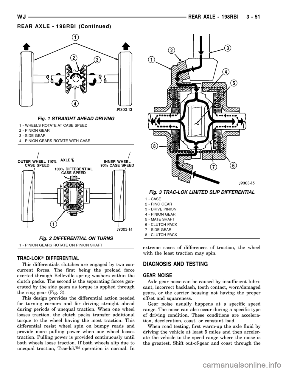
pinion mate shaft but do not rotate around it (Fig. 1).
When turning corners, the outside wheel must
travel a greater distance than the inside wheel to
complete a turn. The difference must be compensated
for to prevent the tires from scuffing and skidding
through turns. To accomplish this, the differential
allows the axle shafts to turn at unequal speeds (Fig.
2). In this instance, the input torque applied to the
pinion gears is not divided equally. The pinion gears
now rotate around the pinion mate shaft in opposite
directions. This allows the side gear and axle shaft
attached to the outside wheel to rotate at a faster
speed.
3 - 50 REAR AXLE - 198RBIWJ
Page 96 of 2199

TRAC-LOKTDIFFERENTIAL
This differentials clutches are engaged by two con-
current forces. The first being the preload force
exerted through Belleville spring washers within the
clutch packs. The second is the separating forces gen-
erated by the side gears as torque is applied through
the ring gear (Fig. 3).
This design provides the differential action needed
for turning corners and for driving straight ahead
during periods of unequal traction. When one wheel
looses traction, the clutch packs transfer additional
torque to the wheel having the most traction. This
differential resist wheel spin on bumpy roads and
provide more pulling power when one wheel looses
traction. Pulling power is provided continuously until
both wheels loose traction. If both wheels slip due to
unequal traction, Trac-lokŸ operation is normal. Inextreme cases of differences of traction, the wheel
with the least traction may spin.DIAGNOSIS AND TESTING
GEAR NOISE
Axle gear noise can be caused by insufficient lubri-
cant, incorrect backlash, tooth contact, worn/damaged
gears, or the carrier housing not having the proper
offset and squareness.
Gear noise usually happens at a specific speed
range. The noise can also occur during a specific type
of driving condition. These conditions are accelera-
tion, deceleration, coast, or constant load.
When road testing, first warm-up the axle fluid by
driving the vehicle at least 5 miles and then acceler-
ate the vehicle to the speed range where the noise is
the greatest. Shift out-of-gear and coast through the
Fig. 1 STRAIGHT AHEAD DRIVING
1 - WHEELS ROTATE AT CASE SPEED
2 - PINION GEAR
3 - SIDE GEAR
4 - PINION GEARS ROTATE WITH CASE
Fig. 2 DIFFERENTIAL ON TURNS
1 - PINION GEARS ROTATE ON PINION SHAFT
Fig. 3 TRAC-LOK LIMITED SLIP DIFFERENTIAL
1 - CASE
2 - RING GEAR
3 - DRIVE PINION
4 - PINION GEAR
5 - MATE SHAFT
6 - CLUTCH PACK
7 - SIDE GEAR
8 - CLUTCH PACK
WJREAR AXLE - 198RBI 3 - 51
REAR AXLE - 198RBI (Continued)
Page 135 of 2199

REAR AXLE - 226RBA
TABLE OF CONTENTS
page page
REAR AXLE - 226RBA
DESCRIPTION.........................90
OPERATION...........................90
DIAGNOSIS AND TESTING................92
REMOVAL.............................95
INSTALLATION.........................96
ADJUSTMENTS........................97
SPECIFICATIONS......................105
SPECIAL TOOLS.......................106
AXLE SHAFTS
REMOVAL............................109
INSTALLATION........................109
AXLE BEARINGS/SEALS
REMOVAL............................109
INSTALLATION........................110
PINION SEAL
REMOVAL............................111
INSTALLATION........................112
COLLAPSIBLE SPACER
REMOVAL............................113INSTALLATION........................114
DIFFERENTIAL
REMOVAL............................115
DISASSEMBLY........................117
ASSEMBLY...........................117
INSTALLATION........................117
DIFFERENTIAL - TRAC-LOK
DIAGNOSIS AND TESTING...............119
DISASSEMBLY........................119
CLEANING...........................121
INSPECTION.........................121
ASSEMBLY...........................121
DIFFERENTIAL CASE BEARINGS
REMOVAL............................123
INSTALLATION........................123
PINION GEAR/RING GEAR
REMOVAL............................124
INSTALLATION........................126
REAR AXLE - 226RBA
DESCRIPTION
The Rear Beam-design Aluminum (RBA) axle hous-
ing has an aluminum center casting (differential
housing) with axle shaft tubes extending from either
side. The tubes are pressed into the differential hous-
ing to form a one-piece axle housing. The axle has
semi-floating axle shafts, meaning that vehicle load
is supported by the axle shaft and bearings.
The differential case is a one-piece design. Differen-
tial bearing preload and ring gear backlash is adjusted
with selective shims. Pinion bearing preload is set and
maintained by the use of a collapsible spacer. The cover
provides a means for inspection and service.
Optional Trac-Loktdifferential differential has a
one-piece differential case, and the same internal
components as a standard differential, plus two
clutch disc packs.
Optional Vari-Loktdifferential has a one-piece dif-
ferential case which contains the gerotor pump
assembly and the clutch mechinism. The unit is ser-
viced only as an assembly.
OPERATION
The axle receives power from the transfer case
through the front propeller shaft. The front propellershaft is connected to the pinion gear which rotates
the differential through the gear mesh with the ring
gear bolted to the differential case. The engine power
is transmitted to the axle shafts through the pinion
mate and side gears. The side gears are splined to
the axle shafts.
STANDARD DIFFERENTIAL
During straight-ahead driving the differential pin-
ion gears do not rotate on the pinion mate shaft. This
occurs because input torque applied to the gears is
divided and distributed equally between the two side
gears. As a result, the pinion gears revolve with the
pinion mate shaft but do not rotate around it (Fig. 1).
When turning corners, the outside wheel must travel
a greater distance than the inside wheel to complete a
turn. The difference must be compensated for to prevent
the tires from scuffing and skidding through turns. To
accomplish this, the differential allows the axle shafts
to turn at unequal speeds (Fig. 2). In this instance, the
input torque applied to the pinion gears is not divided
equally. The pinion gears now rotate around the pinion
mate shaft in opposite directions. This allows the side
gear and axle shaft attached to the outside wheel to
rotate at a faster speed.
3 - 90 REAR AXLE - 226RBAWJ
Page 136 of 2199

TRAC-LOKTDIFFERENTIAL
The differential clutches are engaged by two con-
current forces. The first being the preload force
exerted through Belleville spring washers within the
clutch packs. The second is the separating forces gen-
erated by the side gears as torque is applied through
the ring gear (Fig. 3).
This design provides the differential action needed
for turning corners and for driving straight ahead
during periods of unequal traction. When one wheel
looses traction, the clutch packs transfer additional
torque to the wheel having the most traction. The
differential resist wheel spin on bumpy roads and
provide more pulling power when one wheel looses
traction. Pulling power is provided continuously until
both wheels loose traction. If both wheels slip due tounequal traction, the operation is normal. In extreme
cases of differences of traction, the wheel with the
least traction may spin.VARI-LOKTDIFFERENTIAL
In a standard differential, if one wheel spins, the
opposite wheel will generate only as much torque as
the spinning wheel.
A gerotor pump and clutch pack are used to pro-
vide the torque transfer capability. One axle shaft is
splined to the gerotor pump and one of the differen-
tial side gears, which provides the input to the pump.
As a wheel begins to lose traction, the speed differ-
ential is transmitted from one side of the differential
to the other through the side gears. The motion of
one side gear relative to the other turns the inner
rotor of the pump. Since the outer rotor of the pump
is grounded to the differential case, the inner and
outer rotors are now moving relative to each other
Fig. 1 OPERATION-STRAIGHT AHEAD DRIVING
1 - IN STRAIGHT AHEAD DRIVING EACH WHEEL ROTATES AT
100% OF CASE SPEED
2 - PINION GEAR
3 - SIDE GEAR
4 - PINION GEARS ROTATE WITH CASE
Fig. 2 OPERATION-ON TURNS
1 - PINION GEARS ROTATE ON PINION SHAFT
Fig. 3 TRAC-LOK LIMITED SLIP DIFFERENTIAL
1 - CASE
2 - RING GEAR
3 - DRIVE PINION
4 - PINION GEAR
5 - MATE SHAFT
6 - CLUTCH PACK
7 - SIDE GEAR
8 - CLUTCH PACK
WJREAR AXLE - 226RBA 3 - 91
REAR AXLE - 226RBA (Continued)
Page 177 of 2199

INSTALLATION.........................23
MASTER CYLINDER
DESCRIPTION.........................23
OPERATION...........................24
DIAGNOSIS AND TESTING - MASTER
CYLINDER/POWER BOOSTER...........24
STANDARD PROCEDURE - MASTER
CYLINDER BLEEDING PROCEDURE......25
REMOVAL.............................25
INSTALLATION.........................25
PEDAL
DESCRIPTION
DESCRIPTION - STANDARD PEDAL.......25
DESCRIPTION - ADJUSTABLE PEDALS....25
OPERATION...........................26
REMOVAL
REMOVAL - NON-ADJUSTABLE PEDAL....26
REMOVAL - ADJUSTABLE PEDALS........27
INSTALLATION
INSTALLATION - NON-ADJUSTABLE PEDAL . 28
INSTALLATION - ADJUSTABLE PEDALS....28
PEDAL MOTOR
REMOVAL.............................28
INSTALLATION.........................28
POWER BRAKE BOOSTER
DESCRIPTION.........................29
OPERATION...........................29
REMOVAL.............................31
INSTALLATION.........................31
ROTORS
DIAGNOSIS AND TESTING
DIAGNOSIS AND TESTING - FRONT DISC
BRAKE ROTOR.......................31DIAGNOSIS AND TESTING - REAR DISC
BRAKE ROTOR.......................32
STANDARD PROCEDURE - DISC ROTOR
MACHINING..........................33
REMOVAL
REMOVAL - FRONT DISC BRAKE ROTOR . . 33
REMOVAL - REAR DISC BRAKE ROTOR . . . 33
INSTALLATION
INSTALLATION - FRONT DISC BRAKE
ROTOR .............................34
INSTALLATION - REAR DISC BRAKE
ROTOR .............................34
PARKING BRAKE
OPERATION...........................34
DIAGNOSIS AND TESTING - PARKING BRAKE . 34
CABLES
REMOVAL
REMOVAL - FRONT PARKING BRAKE
CABLE..............................35
REMOVAL - REAR PARKING BRAKE
CABLES............................36
INSTALLATION
INSTALLATION - FRONT PARKING BRAKE
CABLE..............................37
INSTALLATION - REAR PARKING BRAKE
CABLES............................37
LEVER
REMOVAL.............................38
INSTALLATION.........................39
SHOES
REMOVAL.............................39
INSTALLATION.........................39
ADJUSTMENTS - PARKING BRAKE SHOE....40
BRAKES - BASE
DESCRIPTION
Dual piston disc brake calipers are used on the
front. Single piston disc brake calipers are used on
the rear. Ventilated disc brake rotors are used on the
front and solid rotors are used on the rear.
Power brake assist is supplied by a vacuum oper-
ated, dual diaphragm power brake booster. The mas-
ter cylinder used for all applications has an
aluminum body and nylon reservoir with single filler
cap. A fluid level indicator is mounted to the side of
the reservoir.
The braking force of the rear wheels is controlled
by electronic brake distribution (EBD). The EBD
functions like a rear proportioning valve. The EBD
system uses the ABS system to control the slip of the
rear wheels in partial braking range. The braking
force of the rear wheels is controlled electronically by
using the inlet and outlet valves located in the HCU.
Factory installed brake linings on all models con-
sists of organic base material combined with metallic
particles.
DIAGNOSIS AND TESTING - BASE BRAKE
SYSTEM
Base brake components consist of the brake shoes,
calipers, rear park brake drums/rotors, front brake
rotors, brake lines, master cylinder, booster, HCU
and parking brake shoes.
Brake diagnosis involves determining if the prob-
lem is related to a mechanical, hydraulic, electrical
or vacuum operated component.
The first diagnosis step is the preliminary check.
PRELIMINARY BRAKE CHECK
(1) Check condition of tires and wheels. Damaged
wheels and worn, damaged, or underinflated tires
can cause pull, shudder, vibration, and a condition
similar to grab.
5 - 2 BRAKES - BASEWJ