2002 JEEP GRAND CHEROKEE Gear oil
[x] Cancel search: Gear oilPage 1394 of 2199
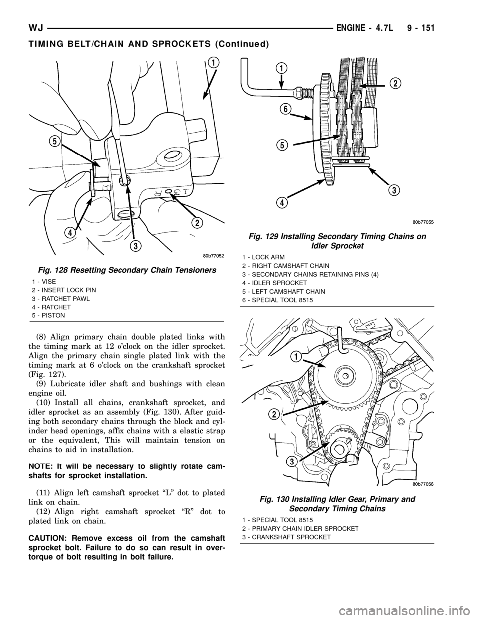
(8) Align primary chain double plated links with
the timing mark at 12 o'clock on the idler sprocket.
Align the primary chain single plated link with the
timing mark at 6 o'clock on the crankshaft sprocket
(Fig. 127).
(9) Lubricate idler shaft and bushings with clean
engine oil.
(10) Install all chains, crankshaft sprocket, and
idler sprocket as an assembly (Fig. 130). After guid-
ing both secondary chains through the block and cyl-
inder head openings, affix chains with a elastic strap
or the equivalent, This will maintain tension on
chains to aid in installation.
NOTE: It will be necessary to slightly rotate cam-
shafts for sprocket installation.
(11) Align left camshaft sprocket ªLº dot to plated
link on chain.
(12) Align right camshaft sprocket ªRº dot to
plated link on chain.
CAUTION: Remove excess oil from the camshaft
sprocket bolt. Failure to do so can result in over-
torque of bolt resulting in bolt failure.
Fig. 128 Resetting Secondary Chain Tensioners
1 - VISE
2 - INSERT LOCK PIN
3 - RATCHET PAWL
4 - RATCHET
5 - PISTON
Fig. 129 Installing Secondary Timing Chains on
Idler Sprocket
1 - LOCK ARM
2 - RIGHT CAMSHAFT CHAIN
3 - SECONDARY CHAINS RETAINING PINS (4)
4 - IDLER SPROCKET
5 - LEFT CAMSHAFT CHAIN
6 - SPECIAL TOOL 8515
Fig. 130 Installing Idler Gear, Primary and
Secondary Timing Chains
1 - SPECIAL TOOL 8515
2 - PRIMARY CHAIN IDLER SPROCKET
3 - CRANKSHAFT SPROCKET
WJENGINE - 4.7L 9 - 151
TIMING BELT/CHAIN AND SPROCKETS (Continued)
Page 1395 of 2199
(13) Remove Special Tool 8515, then attach both
sprockets to camshafts. Remove excess oil from bolts,
then Install sprocket bolts, but do not tighten at this
time.
(14) Verify that all plated links are aligned with
the marks on all sprockets and the ªV8º marks on
camshaft sprockets are at the 12 o'clock position (Fig.
127).
CAUTION: Ensure the plate between the left sec-
ondary chain tensioner and block is correctly
installed.
(15) Install both secondary chain tensioners.
Tighten bolts to 28 N´m (250 in. lbs.).
NOTE: Left and right secondary chain tensioners
are not common.
(16) Before installing idler sprocket bolt, lubricate
washer with oil, and tighten idler sprocket assembly
retaining bolt to 34 N´m (25 ft. lbs.).
(17) Remove all locking pins (3) from tensioners.
CAUTION: After pulling locking pins out of each
tensioner, DO NOT manually extend the tensioner(s)
ratchet. Doing so will over tension the chains,
resulting in noise and/or high timing chain loads.
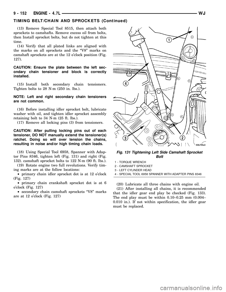
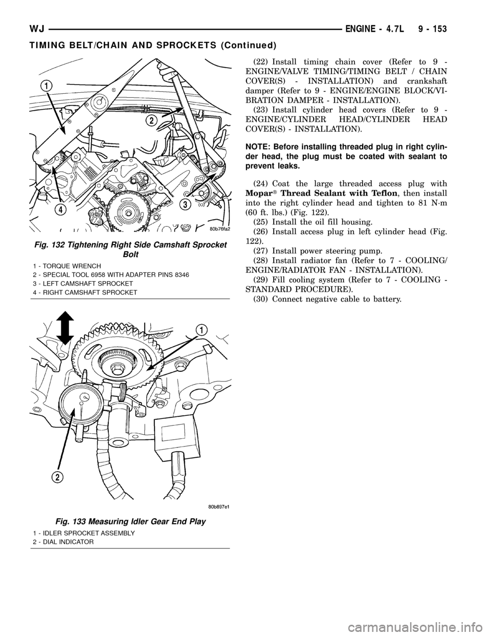
(18) Using Special Tool 6958, Spanner with Adap-
tor Pins 8346, tighten left (Fig. 131) and right (Fig.
132). camshaft sprocket bolts to 122 N´m (90 ft. lbs.).
(19) Rotate engine two full revolutions. Verify tim-
ing marks are at the follow locations:
²primary chain idler sprocket dot is at 12 o'clock
(Fig. 127)
²primary chain crankshaft sprocket dot is at 6
o'clock (Fig. 127)
²secondary chain camshaft sprockets ªV8º marks
are at 12 o'clock (Fig. 127)(20) Lubricate all three chains with engine oil.
(21) After installing all chains, it is recommended
that the idler gear end play be checked (Fig. 133).
The end play must be within 0.10±0.25 mm (0.004±
0.010 in.). If not within specification, the idler gear
must be replaced.
Fig. 131 Tightening Left Side Camshaft Sprocket
Bolt
1 - TORQUE WRENCH
2 - CAMSHAFT SPROCKET
3 - LEFT CYLINDER HEAD
4 - SPECIAL TOOL 6958 SPANNER WITH ADAPTER PINS 8346
9 - 152 ENGINE - 4.7LWJ
TIMING BELT/CHAIN AND SPROCKETS (Continued)
Page 1396 of 2199
(22) Install timing chain cover (Refer to 9 -
ENGINE/VALVE TIMING/TIMING BELT / CHAIN
COVER(S) - INSTALLATION) and crankshaft
damper (Refer to 9 - ENGINE/ENGINE BLOCK/VI-
BRATION DAMPER - INSTALLATION).
(23) Install cylinder head covers (Refer to 9 -
ENGINE/CYLINDER HEAD/CYLINDER HEAD
COVER(S) - INSTALLATION).
NOTE: Before installing threaded plug in right cylin-
der head, the plug must be coated with sealant to
prevent leaks.
(24) Coat the large threaded access plug with
MopartThread Sealant with Teflon, then install
into the right cylinder head and tighten to 81 N´m
(60 ft. lbs.) (Fig. 122).
(25) Install the oil fill housing.
(26) Install access plug in left cylinder head (Fig.
122).
(27) Install power steering pump.
(28) Install radiator fan (Refer to 7 - COOLING/
ENGINE/RADIATOR FAN - INSTALLATION).
(29) Fill cooling system (Refer to 7 - COOLING -
STANDARD PROCEDURE).
(30) Connect negative cable to battery.
Fig. 132 Tightening Right Side Camshaft Sprocket
Bolt
1 - TORQUE WRENCH
2 - SPECIAL TOOL 6958 WITH ADAPTER PINS 8346
3 - LEFT CAMSHAFT SPROCKET
4 - RIGHT CAMSHAFT SPROCKET
Fig. 133 Measuring Idler Gear End Play
1 - IDLER SPROCKET ASSEMBLY
2 - DIAL INDICATOR
WJENGINE - 4.7L 9 - 153
TIMING BELT/CHAIN AND SPROCKETS (Continued)
Page 1493 of 2199
GEAR
TABLE OF CONTENTS
page page
GEAR
DESCRIPTION.........................16
OPERATION...........................16
REMOVAL.............................16
INSTALLATION.........................16
ADJUSTMENTS
STEERING GEAR.....................18
SPECIFICATIONS
POWER STEERING GEAR..............18
SPECIAL TOOLS
POWER STEERING GEAR..............19
PITMAN SHAFT
REMOVAL.............................20INSTALLATION.........................20
PITMAN SHAFT BEARING
REMOVAL.............................22
INSTALLATION.........................22
PITMAN SHAFT SEAL
REMOVAL.............................22
INSTALLATION.........................23
RACK PISTON/VALVE ASSEMBLY
REMOVAL.............................23
INSTALLATION.........................25
STUB SHAFT HOUSING
REMOVAL.............................25
INSTALLATION.........................25
GEAR
DESCRIPTION
The power steering gear is a recirculating ball type
gear (Fig. 1) .
The following gear components can be serviced:
²Pitman Shaft and Cover
²Pitman Shaft Bearings
²Pitman Shaft Oil Seal/Dust Seal
²Stud Shaft Housing with Seal
²O-Rings and Teflon Rings
NOTE: If rack piston assembly is damaged the gear
must be replaced.
OPERATION
The gear acts as a rolling thread between the
worm shaft and rack piston. The worm shaft is sup-
ported by a thrust bearing at the lower end and a
bearing assembly at the upper end. When the worm
shaft is turned the rack piston moves. The rack pis-
ton teeth mesh with the pitman shaft. Turning the
worm shaft turns the pitman shaft, which turns the
steering linkage.
REMOVAL
(1) Place the front wheels in the straight ahead
position with the steering wheel centered and locked.
(2) Remove the air cleaner housing,(Refer to 9 -
ENGINE/AIR INTAKE SYSTEM/AIR CLEANER
HOUSING - REMOVAL).
(3) Drain or siphon the power steering system.(4) Remove the pressure and return lines (Fig.
2)from the steering gear. Refer to hose removal in
this section.
(5) Remove the column coupler shaft bolt (Fig.
2)and remove the shaft from the gear.
(6) Raise and support the vehicle.
(7) Remove the left front wheel and tire assembly.
(8) Remove the pitman arm from gear with Puller
C-4150A.
(9) Remove the windshield washer reservoir,(Refer
to 8 - ELECTRICAL/WIPERS/WASHERS/WASHER
RESERVOIR - REMOVAL).
(10) Remove the steering gear mounting bolts.
Remove the steering gear out of the engine compart-
ment (Fig. 3).
INSTALLATION
(1) Position the steering gear on the frame rail and
install the bolts. Tighten the bolts to 108 N´m (80 ft.
lbs.) torque.
(2) Install the pitman arm and tighten nut to 251
N´m (185 ft. lbs.).
(3) Install windshield washer reservoir,(Refer to 8 -
ELECTRICAL/WIPERS/WASHERS/WASHER RES-
ERVOIR - INSTALLATION).
(4) Install the wheel and tire assembly.
(5) Remove the support and lower the vehicle.
(6) Install the pressure and return hoses to the
steering gear and tighten to 20-38 N´m (14-28 ft.
lbs.).
(7) Install the column coupler shaft.
(8) Install the air cleaner housing,(Refer to 9 -
ENGINE/AIR INTAKE SYSTEM/AIR CLEANER
HOUSING - INSTALLATION).
19 - 16 GEARWJ
Page 1497 of 2199
PITMAN SHAFT
REMOVAL
(1) Clean exposed end of pitman shaft and housing
with a wire brush.
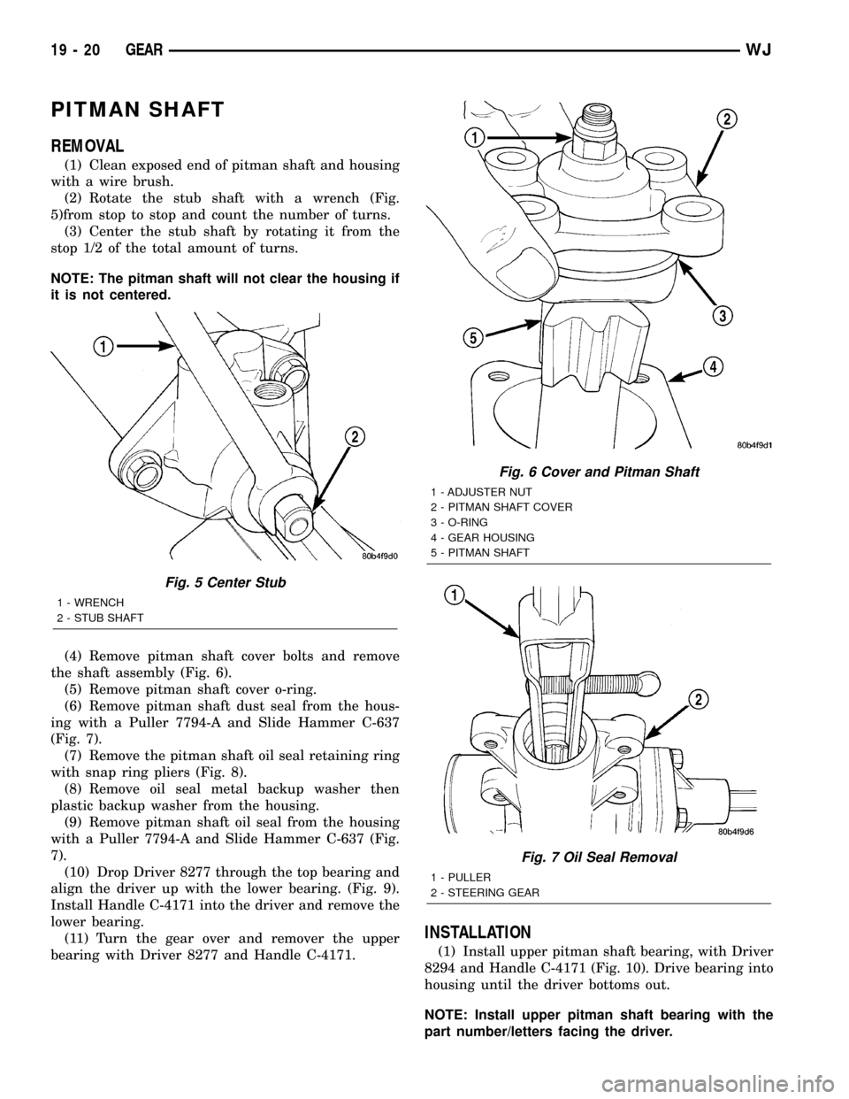
(2) Rotate the stub shaft with a wrench (Fig.
5)from stop to stop and count the number of turns.
(3) Center the stub shaft by rotating it from the
stop 1/2 of the total amount of turns.
NOTE: The pitman shaft will not clear the housing if
it is not centered.
(4) Remove pitman shaft cover bolts and remove
the shaft assembly (Fig. 6).
(5) Remove pitman shaft cover o-ring.
(6) Remove pitman shaft dust seal from the hous-
ing with a Puller 7794-A and Slide Hammer C-637
(Fig. 7).
(7) Remove the pitman shaft oil seal retaining ring
with snap ring pliers (Fig. 8).
(8) Remove oil seal metal backup washer then
plastic backup washer from the housing.
(9) Remove pitman shaft oil seal from the housing
with a Puller 7794-A and Slide Hammer C-637 (Fig.
7).
(10) Drop Driver 8277 through the top bearing and
align the driver up with the lower bearing. (Fig. 9).
Install Handle C-4171 into the driver and remove the
lower bearing.
(11) Turn the gear over and remover the upper
bearing with Driver 8277 and Handle C-4171.
INSTALLATION
(1) Install upper pitman shaft bearing, with Driver
8294 and Handle C-4171 (Fig. 10). Drive bearing into
housing until the driver bottoms out.
NOTE: Install upper pitman shaft bearing with the
part number/letters facing the driver.
Fig. 5 Center Stub
1 - WRENCH
2 - STUB SHAFT
Fig. 6 Cover and Pitman Shaft
1 - ADJUSTER NUT
2 - PITMAN SHAFT COVER
3 - O-RING
4 - GEAR HOUSING
5 - PITMAN SHAFT
Fig. 7 Oil Seal Removal
1 - PULLER
2 - STEERING GEAR
19 - 20 GEARWJ
Page 1498 of 2199
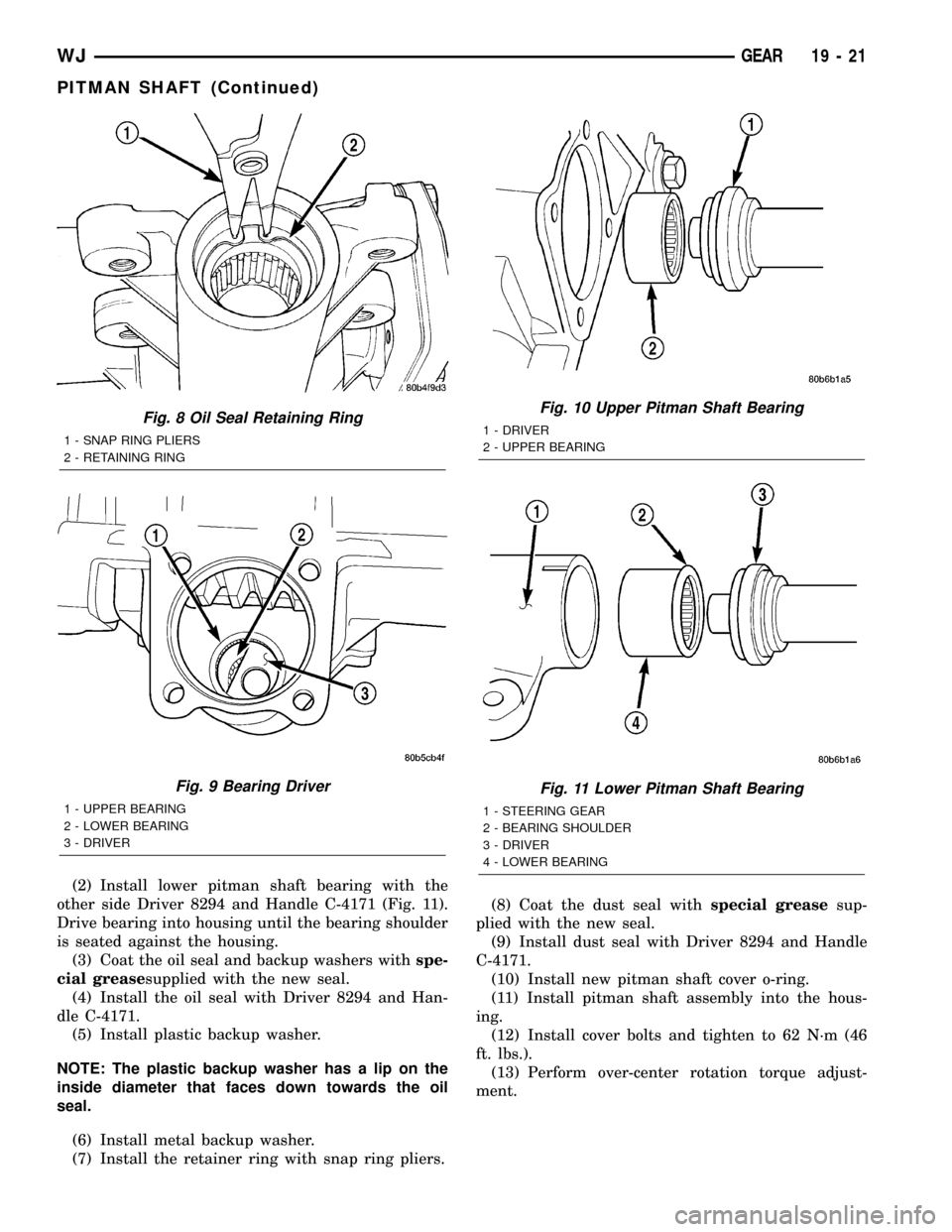
(2) Install lower pitman shaft bearing with the
other side Driver 8294 and Handle C-4171 (Fig. 11).
Drive bearing into housing until the bearing shoulder
is seated against the housing.
(3) Coat the oil seal and backup washers withspe-
cial greasesupplied with the new seal.
(4) Install the oil seal with Driver 8294 and Han-
dle C-4171.
(5) Install plastic backup washer.
NOTE: The plastic backup washer has a lip on the
inside diameter that faces down towards the oil
seal.
(6) Install metal backup washer.
(7) Install the retainer ring with snap ring pliers.(8) Coat the dust seal withspecial greasesup-
plied with the new seal.
(9) Install dust seal with Driver 8294 and Handle
C-4171.
(10) Install new pitman shaft cover o-ring.
(11) Install pitman shaft assembly into the hous-
ing.
(12) Install cover bolts and tighten to 62 N´m (46
ft. lbs.).
(13) Perform over-center rotation torque adjust-
ment.
Fig. 8 Oil Seal Retaining Ring
1 - SNAP RING PLIERS
2 - RETAINING RING
Fig. 9 Bearing Driver
1 - UPPER BEARING
2 - LOWER BEARING
3 - DRIVER
Fig. 10 Upper Pitman Shaft Bearing
1 - DRIVER
2 - UPPER BEARING
Fig. 11 Lower Pitman Shaft Bearing
1 - STEERING GEAR
2 - BEARING SHOULDER
3 - DRIVER
4 - LOWER BEARING
WJGEAR 19 - 21
PITMAN SHAFT (Continued)
Page 1499 of 2199
PITMAN SHAFT BEARING
REMOVAL
(1) Clean exposed end of pitman shaft and housing
with a wire brush.
(2) Rotate the stub shaft with a wrench (Fig.
5)from stop to stop and count the number of turns.
(3) Center the stub shaft by rotating it from the
stop 1/2 of the total amount of turns.
NOTE: The pitman shaft will not clear the housing if
it is not centered.
(4) Remove pitman shaft cover bolts and remove
the shaft assembly (Fig. 6).
(5) Remove pitman shaft cover o-ring.
(6) Remove pitman shaft dust seal from the hous-
ing with a Puller 7794-A and Slide Hammer C-637
(Fig. 7).
(7) Remove the pitman shaft oil seal retaining ring
with snap ring pliers (Fig. 8).
(8) Remove oil seal metal backup washer then
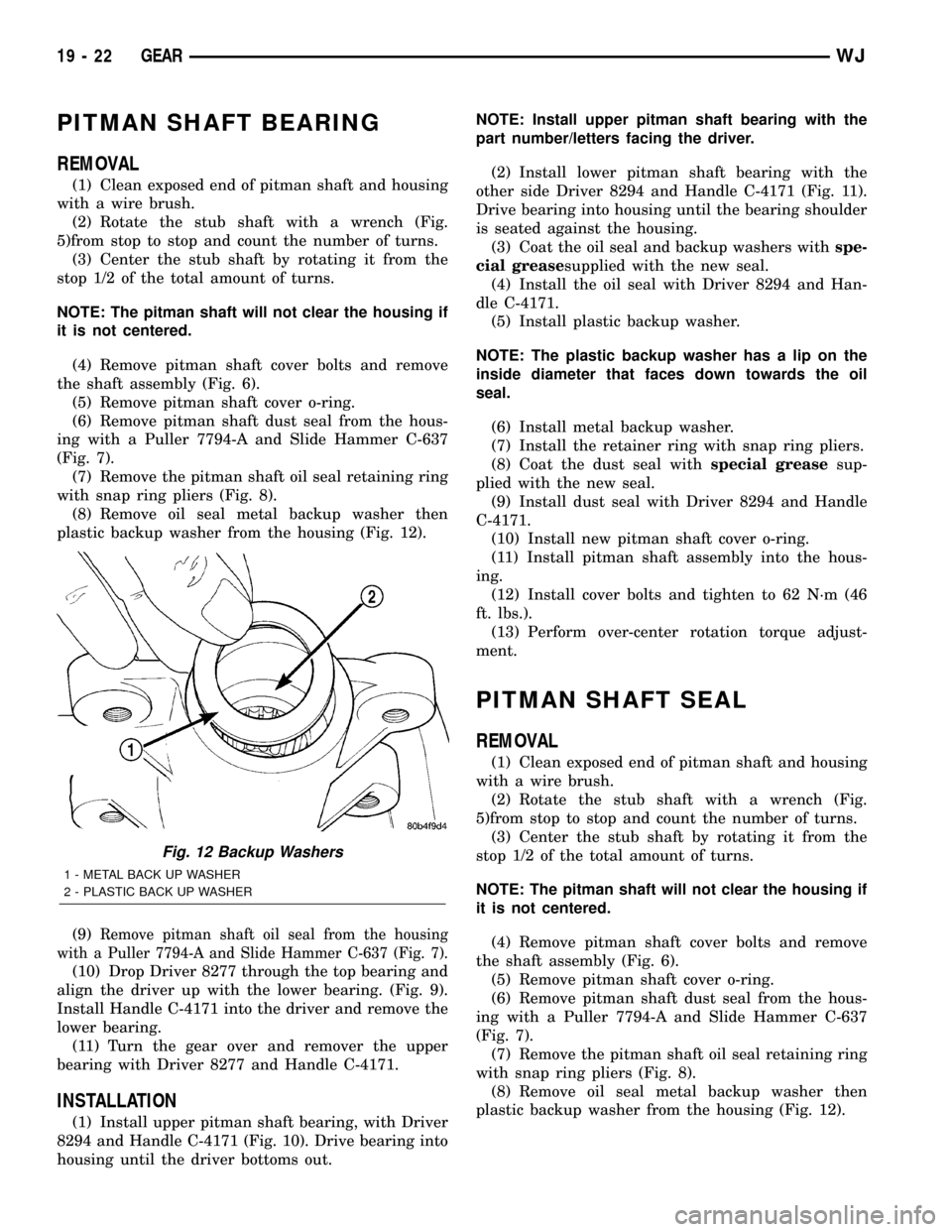
plastic backup washer from the housing (Fig. 12).
(9)
Remove pitman shaft oil seal from the housing
with a Puller 7794-A and Slide Hammer C-637 (Fig. 7).
(10) Drop Driver 8277 through the top bearing and
align the driver up with the lower bearing. (Fig. 9).
Install Handle C-4171 into the driver and remove the
lower bearing.
(11) Turn the gear over and remover the upper
bearing with Driver 8277 and Handle C-4171.
INSTALLATION
(1) Install upper pitman shaft bearing, with Driver
8294 and Handle C-4171 (Fig. 10). Drive bearing into
housing until the driver bottoms out.NOTE: Install upper pitman shaft bearing with the
part number/letters facing the driver.
(2) Install lower pitman shaft bearing with the
other side Driver 8294 and Handle C-4171 (Fig. 11).
Drive bearing into housing until the bearing shoulder
is seated against the housing.
(3) Coat the oil seal and backup washers withspe-
cial greasesupplied with the new seal.
(4) Install the oil seal with Driver 8294 and Han-
dle C-4171.
(5) Install plastic backup washer.
NOTE: The plastic backup washer has a lip on the
inside diameter that faces down towards the oil
seal.
(6) Install metal backup washer.
(7) Install the retainer ring with snap ring pliers.
(8) Coat the dust seal withspecial greasesup-
plied with the new seal.
(9) Install dust seal with Driver 8294 and Handle
C-4171.
(10) Install new pitman shaft cover o-ring.
(11) Install pitman shaft assembly into the hous-
ing.
(12) Install cover bolts and tighten to 62 N´m (46
ft. lbs.).
(13) Perform over-center rotation torque adjust-
ment.
PITMAN SHAFT SEAL
REMOVAL
(1) Clean exposed end of pitman shaft and housing
with a wire brush.
(2) Rotate the stub shaft with a wrench (Fig.
5)from stop to stop and count the number of turns.
(3) Center the stub shaft by rotating it from the
stop 1/2 of the total amount of turns.
NOTE: The pitman shaft will not clear the housing if
it is not centered.
(4) Remove pitman shaft cover bolts and remove
the shaft assembly (Fig. 6).
(5) Remove pitman shaft cover o-ring.
(6) Remove pitman shaft dust seal from the hous-
ing with a Puller 7794-A and Slide Hammer C-637
(Fig. 7).
(7) Remove the pitman shaft oil seal retaining ring
with snap ring pliers (Fig. 8).
(8) Remove oil seal metal backup washer then
plastic backup washer from the housing (Fig. 12).
Fig. 12 Backup Washers
1 - METAL BACK UP WASHER
2 - PLASTIC BACK UP WASHER
19 - 22 GEARWJ
Page 1500 of 2199
(9) Remove pitman shaft oil seal from the housing
with a Puller 7794-A and Slide Hammer C-637 (Fig.
7).
(10) Drop Driver 8277 through the top bearing and
align the driver up with the lower bearing. (Fig. 9).
Install Handle C-4171 into the driver and remove the
lower bearing.
(11) Turn the gear over and remover the upper
bearing with Driver 8277 and Handle C-4171.
INSTALLATION
(1) Install upper pitman shaft bearing, with Driver
8294 and Handle C-4171 (Fig. 10). Drive bearing into
housing until the driver bottoms out.
NOTE: Install upper pitman shaft bearing with the
part number/letters facing the driver.
(2) Install lower pitman shaft bearing with the
other side Driver 8294 and Handle C-4171 (Fig. 11).
Drive bearing into housing until the bearing shoulder
is seated against the housing.
(3) Coat the oil seal and backup washers withspe-
cial greasesupplied with the new seal.
(4) Install the oil seal with Driver 8294 and Han-
dle C-4171.
(5) Install plastic backup washer.
NOTE: The plastic backup washer has a lip on the
inside diameter that faces down towards the oil
seal.
(6) Install metal backup washer.
(7) Install the retainer ring with snap ring pliers.
(8) Coat the dust seal withspecial greasesup-
plied with the new seal.
(9) Install dust seal with Driver 8294 and Handle
C-4171.
(10) Install new pitman shaft cover o-ring.
(11) Install pitman shaft assembly into the hous-
ing.
(12) Install cover bolts and tighten to 62 N´m (46
ft. lbs.).
(13) Perform over-center rotation torque adjust-
ment.
RACK PISTON/VALVE
ASSEMBLY
REMOVAL
(1) Remove the steering gear (Refer to 19 -
STEERING/GEAR - REMOVAL).
(2) Clean exposed end of pitman shaft and housing
with a wire brush.
(3) Rotate the stub shaft with a wrench (Fig.
5)from stop to stop and count the number of turns.(4) Center the stub shaft by rotating it from the
stop 1/2 of the total amount of turns.
NOTE: The pitman shaft will not clear the housing if
it is not centered.
(5) Remove pitman shaft cover bolts and remove
the shaft assembly (Fig. 6).
(6) Remove the pitman shaft cover o-ring.
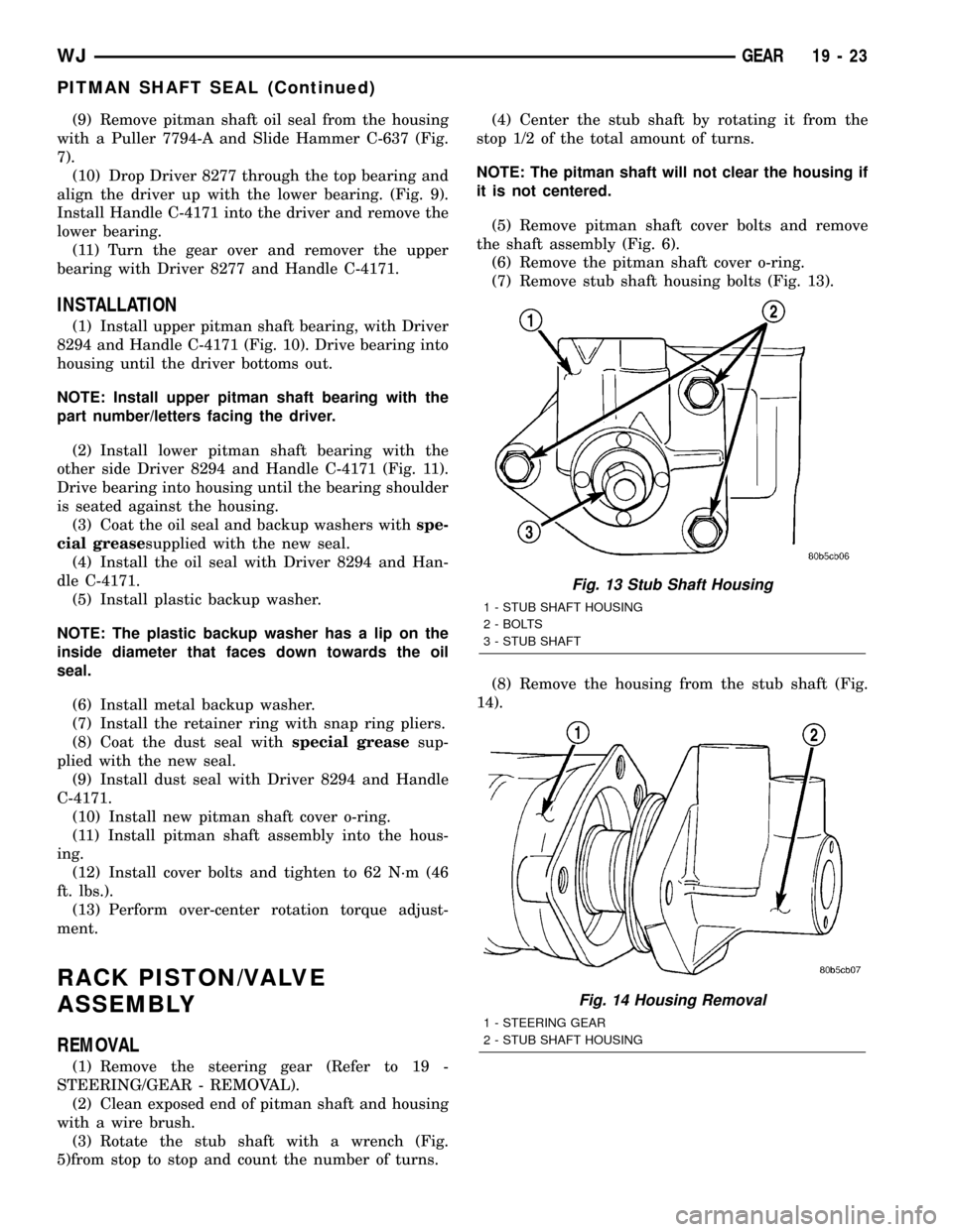
(7) Remove stub shaft housing bolts (Fig. 13).
(8) Remove the housing from the stub shaft (Fig.
14).
Fig. 13 Stub Shaft Housing
1 - STUB SHAFT HOUSING
2 - BOLTS
3 - STUB SHAFT
Fig. 14 Housing Removal
1 - STEERING GEAR
2 - STUB SHAFT HOUSING
WJGEAR 19 - 23
PITMAN SHAFT SEAL (Continued)