2002 JEEP GRAND CHEROKEE Gear oil
[x] Cancel search: Gear oilPage 160 of 2199

NOTE: If more than 380 N´m (280 ft. lbs.) torque is
required to crush the collapsible spacer, the spacer
is defective and must be replaced.
(7) Check rotating torque with an inch pound
torque wrench (Fig. 44). The rotating torque of the
pinion gear should be, the reading recorded during
removal plus an additional 0.56 N´m (5 in. lbs.).
(8)
Install propeller shaft with reference marks align.
(9) Install rear brake rotors and calipers.
(10) Add gear lubricant, if necessary.
(11) Install wheel and tire assemblies.
(12) Remove supports and lower vehicle.
DIFFERENTIAL
REMOVAL
(1) Raise and support vehicle.
(2) Remove fill hole plug from the differential
housing cover.
(3) Remove differential housing cover and drain
fluid.
(4) Clean the housing cavity with flushing oil, light
engine oil or lint free cloth.
NOTE: Do not use water, steam, kerosene or gaso-
line for cleaning.
(5) Remove axle shafts.(6)
Note the reference letters stamped on the bearing
caps and housing machined sealing surface (Fig. 45).
(7) Loosen the differential bearing cap bolts.
(8) Position Spreader W-129-B with Adapter Kit
6987B on differential locating holes (Fig. 46). Install
holddown clamps and tighten the turnbuckle finger-
tight.
Fig. 44 PINION ROTATING TORQUE
1 - TORQUE WRENCH
2 - PINION YOKE
Fig. 45 BEARING CAP REFERENCE
1 - REFERENCE LETTERS
2 - REFERENCE LETTERS
Fig. 46 SPREADER LOCATION
1 - DIFFERENTIAL HOUSING
2 - DOWEL
3 - SAFETY HOLD DOWN
4 - SPREADER
5 - TURNBUCKLE
WJREAR AXLE - 226RBA 3 - 115
COLLAPSIBLE SPACER (Continued)
Page 162 of 2199

DISASSEMBLY
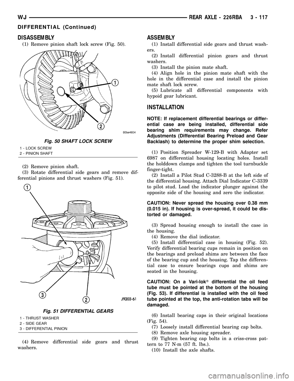
(1) Remove pinion shaft lock screw (Fig. 50).
(2) Remove pinion shaft.
(3) Rotate differential side gears and remove dif-
ferential pinions and thrust washers (Fig. 51).
(4) Remove differential side gears and thrust
washers.
ASSEMBLY
(1) Install differential side gears and thrust wash-
ers.
(2) Install differential pinion gears and thrust
washers.
(3) Install the pinion mate shaft.
(4) Align hole in the pinion mate shaft with the
hole in the differential case and install the pinion
mate shaft lock screw.
(5) Lubricate all differential components with
hypoid gear lubricant.
INSTALLATION
NOTE: If replacement differential bearings or differ-
ential case are being installed, differential side
bearing shim requirements may change. Refer
Adjustments (Differential Bearing Preload and Gear
Backlash) to determine the proper shim selection.
(1) Position Spreader W-129-B with Adapter set
6987 on differential housing locating holes. Install
the holddown clamps and tighten the tool turnbuckle
finger-tight.
(2) Install a Pilot Stud C-3288-B at the left side of
the differential housing. Attach Dial Indicator C-3339
to pilot stud. Load the indicator plunger against the
opposite side of the housing and zero the indicator.
CAUTION: Never spread the housing over 0.38 mm
(0.015 in). If housing is over-spread, it could be dis-
torted or damaged.
(3) Spread housing enough to install the case in
the housing.
(4) Remove the dial indicator.
(5) Install differential case in housing (Fig. 52).
Verify differential bearing cups remain in position on
the bearings and preload shims are between the face
of the bearing cup and the housing. Tap the differen-
tial case to ensure bearings cups and shims are
seated in the housing.
CAUTION: On a Vari-lokTdifferential the oil feed
tube must be pointed at the bottom of the housing
(Fig. 53). If differential is installed with the oil feed
tube pointed at the top, the anti-rotation tabs will be
damaged.
(6) Install bearing caps in their original locations
(Fig. 54).
(7) Loosely install differential bearing cap bolts.
(8) Remove axle housing spreader.
(9) Tighten bearing cap bolts in a criss-cross pat-
tern to 77 N´m (57 ft. lbs.).
(10) Install the axle shafts.
Fig. 50 SHAFT LOCK SCREW
1 - LOCK SCREW
2 - PINION SHAFT
Fig. 51 DIFFERENTIAL GEARS
1 - THRUST WASHER
2 - SIDE GEAR
3 - DIFFERENTIAL PINION
WJREAR AXLE - 226RBA 3 - 117
DIFFERENTIAL (Continued)
Page 170 of 2199

(9) Remove pinion yoke from pinion shaft with
Remover C-452 and Wrench C-3281 (Fig. 73).
(10) Remove pinion gear from housing (Fig. 74).(11) Remove pinion seal with Remover 7794-A and
a slide hammer (Fig. 75).
(12) Remove oil slinger, if equipped, and front pin-
ion bearing.
(13) Remove the front pinion bearing cup with
Remover D-103 and Handle C-4171 (Fig. 76).
Fig. 73 Pinion Yoke Remover
1 - FLANGE WRENCH
2 - YOKE
3 - YOKE PULLER
Fig. 74 Pinion Gear
1 - RAWHIDE HAMMER
Fig. 75 Pinion Seal Remover
1 - REMOVER
2 - SLIDE HAMMER
3 - PINION SEAL
Fig. 76 Front Pinion Bearing Cup
1 - REMOVER
2 - HANDLE
WJREAR AXLE - 226RBA 3 - 125
PINION GEAR/RING GEAR (Continued)
Page 171 of 2199

(14) Remove rear bearing cup from housing (Fig.
77) with Remover C-4307 and Handle C-4171.
(15) Remove collapsible preload spacer (Fig. 78).
(16) Remove rear bearing from the pinion with
Puller/Press C-293-PA and Adapters C-293-42 (Fig.
79).
(17) Remove depth shims from the pinion gear
shaft and record shim thickness.
INSTALLATION
NOTE: A pinion depth shim/oil slinger is placed
between the rear pinion bearing cone and the pin-
ion head to achieve proper ring gear and pinion
mesh. If ring gear and pinion are reused, the pinion
depth shim/oil slinger should not require replace-
ment. Refer to Adjustment (Pinion Gear Depth) to
select the proper thickness shim/oil slinger if ring
and pinion gears are replaced.
Fig. 77 Rear Pinion Bearing Cup
1 - REMOVER
2 - HANDLE
Fig. 78 Collapsible Spacer
1 - COLLAPSIBLE SPACER
2 - SHOULDER
3 - PINION GEAR
4 - DEPTH SHIM
5 - REAR BEARING
Fig. 79 Rear Pinion Bearing Puller
1 - PULLER
2 - VISE
3 - ADAPTERS
4 - PINION GEAR SHAFT
3 - 126 REAR AXLE - 226RBAWJ
PINION GEAR/RING GEAR (Continued)
Page 172 of 2199

(1) Apply Mopar Door Ease or equivalent lubricant
to outside surface of pinion bearing cups.
(2) Install pinion rear bearing cup with Installer
C-4308 and Driver Handle C-4171 (Fig. 80) and ver-
ify cup is seated.
(3) Install pinion front bearing cup with Installer
D-129 and Handle C-4171 (Fig. 81) and verify cup is
seated.(4) Install pinion front bearing and oil slinger, if
equipped.
(5) Apply a light coating of gear lubricant on the
lip of pinion seal. Install seal with an appropriate
(Fig. 82).
(6) Install depth shim on the pinion gear.
(7) Install rear bearing on the pinion gear with
Installer 6448 and a press (Fig. 83).
Fig. 80 Rear Pinion Bearing Cup
1 - INSTALLER
2 - HANDLE
Fig. 81 FRONT PINION BEARING CUP
1 - INSTALLER
2 - HANDLE
Fig. 82 PINION SEAL INSTALLER
1 - HANDLE
2 - INSTALLER
Fig. 83 REAR PINION BEARING
1 - PRESS
2 - INSTALLER
3 - PINION GEAR
4 - PINION BEARING
WJREAR AXLE - 226RBA 3 - 127
PINION GEAR/RING GEAR (Continued)
Page 174 of 2199

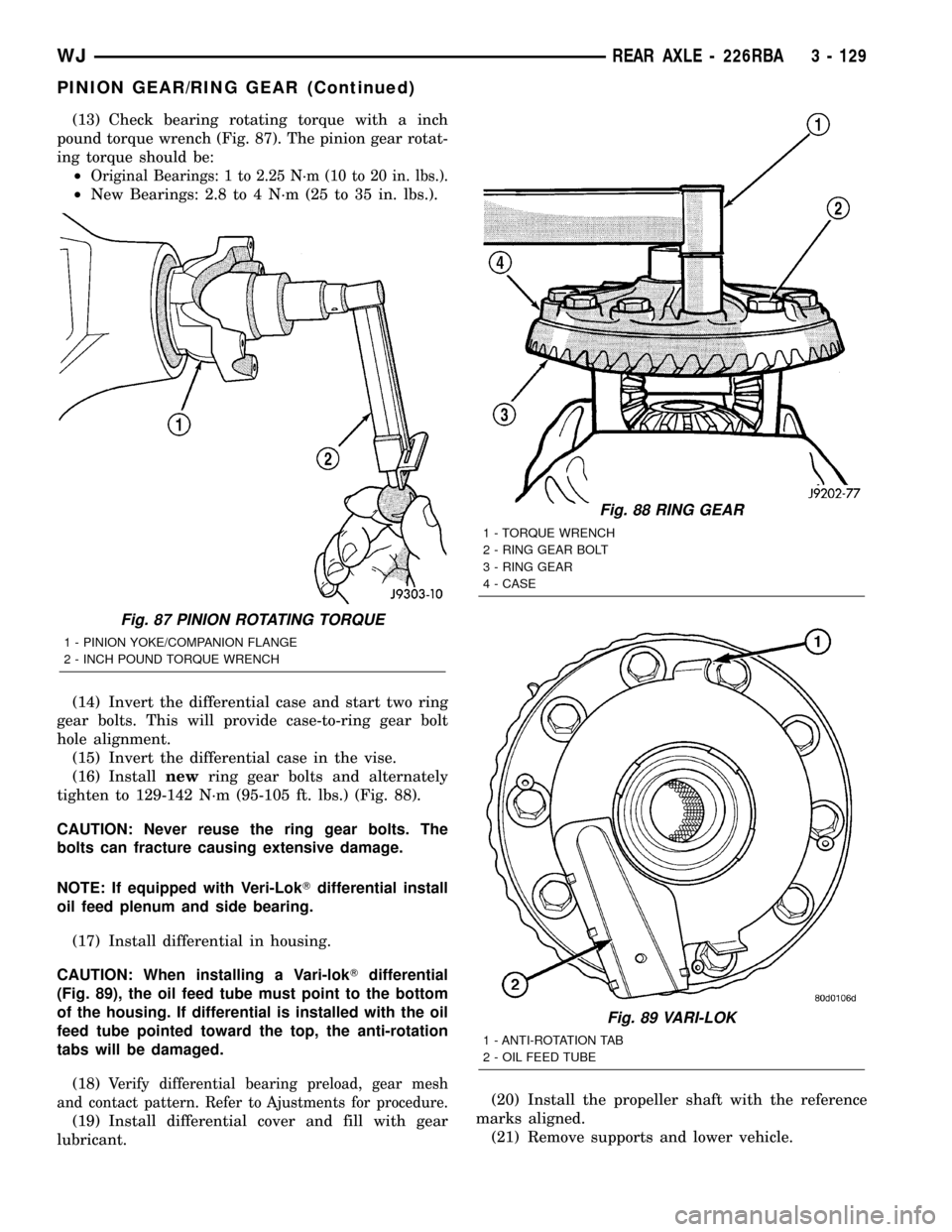
(13) Check bearing rotating torque with a inch
pound torque wrench (Fig. 87). The pinion gear rotat-
ing torque should be:
²
Original Bearings: 1 to 2.25 N´m (10 to 20 in. lbs.).
²New Bearings: 2.8 to 4 N´m (25 to 35 in. lbs.).
(14) Invert the differential case and start two ring
gear bolts. This will provide case-to-ring gear bolt
hole alignment.
(15) Invert the differential case in the vise.
(16) Installnewring gear bolts and alternately
tighten to 129-142 N´m (95-105 ft. lbs.) (Fig. 88).
CAUTION: Never reuse the ring gear bolts. The
bolts can fracture causing extensive damage.
NOTE: If equipped with Veri-LokTdifferential install
oil feed plenum and side bearing.
(17) Install differential in housing.
CAUTION: When installing a Vari-lokTdifferential
(Fig. 89), the oil feed tube must point to the bottom
of the housing. If differential is installed with the oil
feed tube pointed toward the top, the anti-rotation
tabs will be damaged.
(18)
Verify differential bearing preload, gear mesh
and contact pattern. Refer to Ajustments for procedure.
(19) Install differential cover and fill with gear
lubricant.(20) Install the propeller shaft with the reference
marks aligned.
(21) Remove supports and lower vehicle.
Fig. 87 PINION ROTATING TORQUE
1 - PINION YOKE/COMPANION FLANGE
2 - INCH POUND TORQUE WRENCH
Fig. 88 RING GEAR
1 - TORQUE WRENCH
2 - RING GEAR BOLT
3 - RING GEAR
4 - CASE
Fig. 89 VARI-LOK
1 - ANTI-ROTATION TAB
2 - OIL FEED TUBE
WJREAR AXLE - 226RBA 3 - 129
PINION GEAR/RING GEAR (Continued)
Page 251 of 2199

²Fan control valve
²Two stage G-rotor hydraulic drive
The hydraulic fan and drive is not serviceable.
Therefore any failure of the fan blade, hydraulic fan
drive or fan shroud requires replacement of the fan
module because the fan blade and hydraulic fan drive
are matched and balanced as a system and servicing
either separately would disrupt this balance.
For hydraulic fluid routing information refer to
(Fig. 5).
CAUTION: Do not attempt to service the hydraulic
cooling fan or fan drive separately replace the cooling
module as an assembly. Failure to do so may cause
severe damage to the hydraulic cooling fan assembly.
OPERATION
The hydraulic radiator cooling fan used on the
Grand Cherokee with the 4.7L engine replaces both
the electric fan and the engine driven mechanical
fan. The use of this hydraulic fan provides the 4.7L
equipped Grand Cherokee with heavy trailer tow
capability while at the same time reducing unneces-
sary power drain on both the engine and the vehicles
electrical system.
HYDRAULIC FAN STRATEGY
The hydraulic radiator cooling fan is controlled by
the JTEC. A PWM (Pulse With Modulated) signal
from the JTEC controls the fan from 0 to 100% of the
available fan speed. There are four inputs to the
JTEC that determine what speed percentage of fan is
required by the vehicle. These inputs are:
²Engine Coolant Temperature
²Transmission Oil Temperature
²Battery Temperature
²A/C System Pressure
By monitoring these four parameters, the JTEC
can determine if cooling airflow is required. If airflow
is required, the JTEC will slowly ramp up (speed up)
the fan speed until the parameter(s) are under con-
trol. Once the temperature or pressure is reduced to
within operating parameters the fan will ramp up,
ramp down, or hold its speed to maintain the temper-
ature / pressure requirements.
NOTE: Even if the JTEC is not requesting fan on
operation the fan blade will usually spin between
100 and 500 RPM when the vehicle is at idle. This is
due to a controlled minimum oil flow requirement
through the fan drive motor.
ACTIVATING THE HYDRAULIC FAN WITH THE DRB
Under the Engine Systems test heading, there is a
subheading. ªHydraulic fan solenoid testº, that has
the selections, on /off. Activating the fan with the
DRB will run the fan at 100% duty cycle, which will
help troubleshoot any system problems, and also help
with the deaeration procedure.
NOTE: Engine must be running to activate the fan
with the DRB.
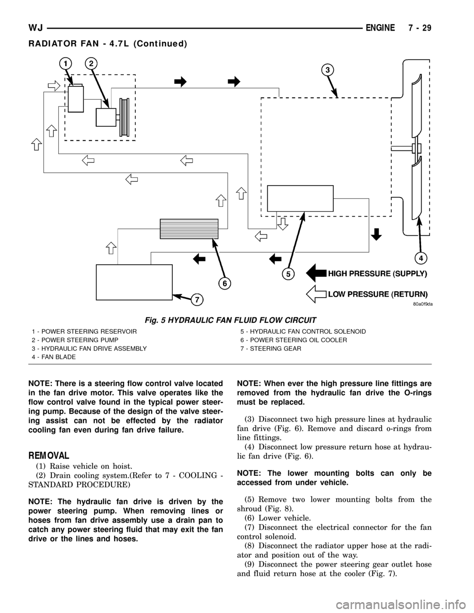
RADIATOR COOLING FAN HYDRAULIC FLUID PATH
Hydraulic fluid is pumped through the power
steering pump, from the pump the fluid travels
though a high pressure delivery line to the fan drive
motor. As fluid is diverted through the G-rotors, rota-
tional motion is created as fluid moves from the high-
pressure (inlet) side of the motor to the low-pressure
(outlet) side. Fluid exiting the drive motor is divided
into two paths. Path one continues through a high
pressure delivery line to the vehicles steering gear to
provide steering assist. and path two sends fluid
back to the power steering pump through a low pres-
sure line. Fluid exits the steering gear under low
pressure and travels through a low pressure line to
the power steering fluid cooler to be cooled before
being returned back the the power steering fluid res-
ervoir (Fig. 5).
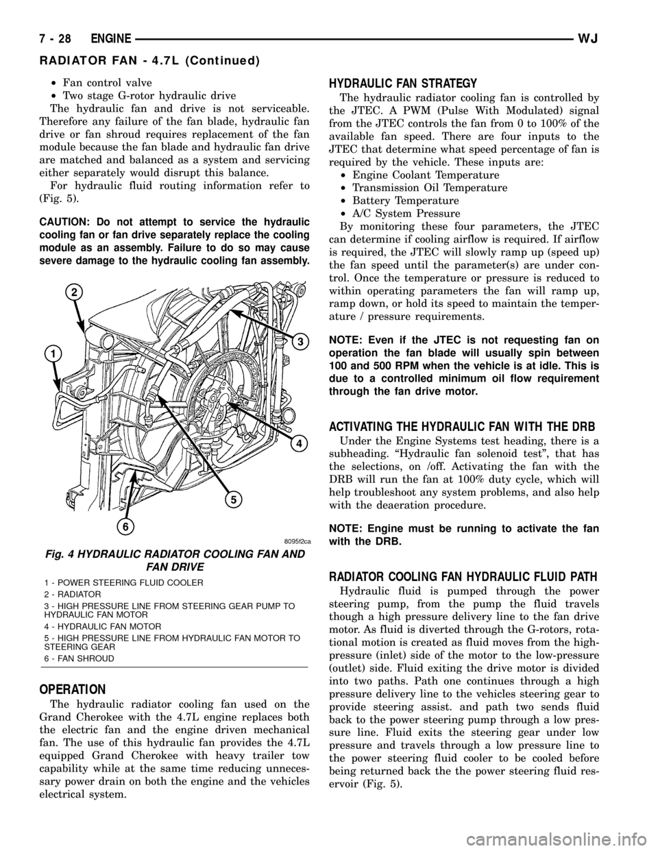
Fig. 4 HYDRAULIC RADIATOR COOLING FAN AND
FAN DRIVE
1 - POWER STEERING FLUID COOLER
2 - RADIATOR
3 - HIGH PRESSURE LINE FROM STEERING GEAR PUMP TO
HYDRAULIC FAN MOTOR
4 - HYDRAULIC FAN MOTOR
5 - HIGH PRESSURE LINE FROM HYDRAULIC FAN MOTOR TO
STEERING GEAR
6 - FAN SHROUD
7 - 28 ENGINEWJ
RADIATOR FAN - 4.7L (Continued)
Page 252 of 2199

NOTE: There is a steering flow control valve located
in the fan drive motor. This valve operates like the
flow control valve found in the typical power steer-
ing pump. Because of the design of the valve steer-
ing assist can not be effected by the radiator
cooling fan even during fan drive failure.
REMOVAL
(1) Raise vehicle on hoist.
(2) Drain cooling system.(Refer to 7 - COOLING -
STANDARD PROCEDURE)
NOTE: The hydraulic fan drive is driven by the
power steering pump. When removing lines or
hoses from fan drive assembly use a drain pan to
catch any power steering fluid that may exit the fan
drive or the lines and hoses.NOTE: When ever the high pressure line fittings are
removed from the hydraulic fan drive the O-rings
must be replaced.
(3) Disconnect two high pressure lines at hydraulic
fan drive (Fig. 6). Remove and discard o-rings from
line fittings.
(4) Disconnect low pressure return hose at hydrau-
lic fan drive (Fig. 6).
NOTE: The lower mounting bolts can only be
accessed from under vehicle.
(5) Remove two lower mounting bolts from the
shroud (Fig. 8).
(6) Lower vehicle.
(7) Disconnect the electrical connector for the fan
control solenoid.
(8) Disconnect the radiator upper hose at the radi-
ator and position out of the way.
(9) Disconnect the power steering gear outlet hose
and fluid return hose at the cooler (Fig. 7).
Fig. 5 HYDRAULIC FAN FLUID FLOW CIRCUIT
1 - POWER STEERING RESERVOIR
2 - POWER STEERING PUMP
3 - HYDRAULIC FAN DRIVE ASSEMBLY
4 - FAN BLADE5 - HYDRAULIC FAN CONTROL SOLENOID
6 - POWER STEERING OIL COOLER
7 - STEERING GEAR
WJENGINE 7 - 29
RADIATOR FAN - 4.7L (Continued)