2002 JEEP GRAND CHEROKEE seat mount
[x] Cancel search: seat mountPage 648 of 2199
the washer fluid and forces it through the pump out-
let nipple, the rear washer plumbing, and the rear
washer nozzle onto the liftgate glass.
REMOVAL
(1) Disconnect and isolate the battery negative
cable.
(2) Raise and support the vehicle.
(3) Remove the liner from the left front fender
wheel house.
(4) Disconnect the left headlamp and dash wire
harness connector for the rear washer pump/motor
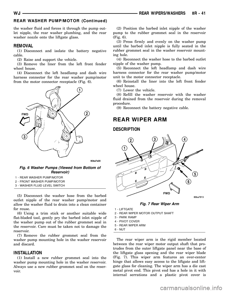
from the motor connector receptacle (Fig. 6).
(5) Disconnect the washer hose from the barbed
outlet nipple of the rear washer pump/motor and
allow the washer fluid to drain into a clean container
for reuse.
(6) Using a trim stick or another suitable wide
flat-bladed tool, gently pry the barbed inlet nipple of
the washer pump out of the rubber grommet seal in
the reservoir. Care must be taken not to damage the
reservoir.
(7) Remove the rubber grommet seal from the
washer pump mounting hole in the washer reservoir
and discard.
INSTALLATION
(1) Install a new rubber grommet seal into the
washer pump mounting hole in the washer reservoir.
Always use a new rubber grommet seal on the reser-
voir.(2) Position the barbed inlet nipple of the washer
pump to the rubber grommet seal in the reservoir
(Fig. 6).
(3) Press firmly and evenly on the washer pump
until the barbed inlet nipple is fully seated in the
rubber grommet seal in the washer reservoir mount-
ing hole.
(4) Reconnect the washer hose to the barbed outlet
nipple of the washer pump.
(5) Reconnect the left headlamp and dash wire
harness connector for the rear washer pump/motor
unit to the motor connector receptacle.
(6) Reinstall the liner into the left front fender
wheel house.
(7) Lower the vehicle.
(8) Refill the washer reservoir with the washer
fluid drained from the reservoir during the removal
procedure.
(9) Reconnect the battery negative cable.
REAR WIPER ARM
DESCRIPTION
The rear wiper arm is the rigid member located
between the rear wiper motor output shaft that pro-
trudes from the outer liftgate panel near the base of
the liftgate glass opening and the rear wiper blade
(Fig. 7). This wiper arm features an over-center
hinge that allows easy access to the liftgate and lift-
gate glass for cleaning. The wiper arm has a die cast
metal pivot end. This pivot end has a hole in it with
internal serrations and a plastic pivot cover is
Fig. 6 Washer Pumps (Viewed from Bottom of
Reservoir)
1 - REAR WASHER PUMP/MOTOR
2 - FRONT WASHER PUMP/MOTOR
3 - WASHER FLUID LEVEL SWITCH
Fig. 7 Rear Wiper Arm
1 - LIFTGATE
2 - REAR WIPER MOTOR OUTPUT SHAFT
3 - PARK RAMP
4 - PIVOT COVER
5 - REAR WIPER ARM
6 - NUT
WJREAR WIPERS/WASHERS 8R - 41
REAR WASHER PUMP/MOTOR (Continued)
Page 663 of 2199

²Ohmmeter - Used to check the resistance
between two points of a circuit. Low or no resistance
in a circuit means good continuity.
CAUTION: Most of the electrical components used
in today's vehicles are Solid State. When checking
resistance in these circuits use a meter with a 10 -
megohm or greater impedance rating. In addition,
make sure the power is disconnected from the cir-
cuit. Circuits that are powered up by the vehicle's
electrical system can cause damage to the equip-
ment and provide false readings.
²Probing Tools - These tools are used for probing
terminals in connectors (Fig. 5). Select the proper
size tool from Special Tool Package 6807, and insert
it into the terminal being tested. Use the other end
of the tool to insert the meter probe.
INTERMITTENT AND POOR CONNECTIONS
Most intermittent electrical problems are caused
by faulty electrical connections or wiring. It is also
possible for a sticking component or relay to cause a
problem. Before condemning a component or wiring
assembly, check the following items.
²Connectors are fully seated
²Spread terminals, or terminal push out
²Terminals in the wiring assembly are fully
seated into the connector/component and locked into
position
²
Dirt or corrosion on the terminals. Any amount of
corrosion or dirt could cause an intermittent problem
²Damaged connector/component casing exposing
the item to dirt or moisture
²Wire insulation that has rubbed through causing
a short to ground
²Some or all of the wiring strands broken inside
of the insulation
²Wiring broken inside of the insulation
TROUBLESHOOTING WIRING PROBLEMS
When troubleshooting wiring problems there are
six steps which can aid in the procedure. The stepsare listed and explained below. Always check for non-
factory items added to the vehicle before doing any
diagnosis. If the vehicle is equipped with these items,
disconnect them to verify these add-on items are not
the cause of the problem.
(1) Verify the problem.
(2) Verify any related symptoms. Do this by per-
forming operational checks on components that are
in the same circuit. Refer to the wiring diagrams.
(3) Analyze the symptoms. Use the wiring dia-
grams to determine what the circuit is doing, where
the problem most likely is occurring and where the
diagnosis will continue.
(4) Isolate the problem area.
(5) Repair the problem area.
(6) Verify the proper operation. For this step,
check for proper operation of all items on the
repaired circuit. Refer to the wiring diagrams.
STANDARD PROCEDURE
STANDARD PROCEDURE - ELECTROSTATIC
DISCHARGE (ESD) SENSITIVE DEVICES
All ESD sensitive components are solid state and a
symbol (Fig. 6) is used to indicate this. When handling
any component with this symbol, comply with the fol-
lowing procedures to reduce the possibility of electro-
static charge build up on the body and inadvertent
discharge into the component. If it is not known
whether the part is ESD sensitive, assume that it is.
(1) Always touch a known good ground before han-
dling the part. This should be repeated while han-
dling the part and more frequently after sliding
across a seat, sitting down from a standing position,
or walking a distance.
(2) Avoid touching electrical terminals of the part,
unless instructed to do so by a written procedure.
(3) When using a voltmeter, be sure to connect the
ground lead first.
(4) Do not remove the part form it's protective
packing until it is time to install the part.
(5) Before removing the part from it's pakage,
ground the pakage to a known good ground on the
vehicle.
Fig. 5 PROBING TOOL
1 - SPECIAL TOOL 6801
2 - PROBING END
Fig. 6 ELECTROSTATIC DISCHARGE SYMBOL
8W - 01 - 8 8W-01 WIRING DIAGRAM INFORMATIONWJ
WIRING DIAGRAM INFORMATION (Continued)
Page 672 of 2199

8W-02 COMPONENT INDEX
Component Page
A/C Compressor Clutch................. 8W-42
A/C Pressure Transducer................ 8W-42
Accelerator Pedal Position Sensor......... 8W-30
Accessory Delay Relay.................. 8W-64
Adjustable Pedals..................... 8W-30
Airbags............................. 8W-43
Ambient Temperature Sensor............ 8W-45
Antennas............................ 8W-47
Ash Receiver Lamp.................... 8W-44
Auto Shut Down Relay................. 8W-30
Automatic Day/Night Mirror............. 8W-49
Automatic Headlamp Light Sensor/VTSS
LED.............................. 8W-39
Automatic Zone Control Module.......... 8W-42
Back-Up Lamp Relay................... 8W-51
Battery Temperature Sensor............. 8W-30
Battery............................. 8W-20
Blend Door Motor/Actuator.............. 8W-42
Blower Motor......................... 8W-42
Body Control Module................... 8W-45
Boost Pressure Sensor.................. 8W-30
Brake Lamp Switch.................... 8W-33
Camshaft Position Sensor............... 8W-30
Capacitors........................... 8W-30
Cargo Lamp.......................... 8W-44
Center High Mounted Stop Lamp......... 8W-51
Cigar Lighter......................... 8W-41
Circuit Breakers...................... 8W-12
Clockspring.................. 8W-33, 41, 43, 47
Coil On Plugs......................... 8W-30
Coil Rail............................. 8W-30
Combination Flasher................... 8W-52
Compact Disc Changer.................. 8W-47
Controller Antilock Brake............... 8W-35
Coolant Level Sensor................... 8W-45
Courtesy Lamps....................... 8W-44
Crankcase Heater..................... 8W-30
Crankshaft Position Sensor.............. 8W-30
Cylinder Lock Switches................. 8W-61
Data Link Connector................... 8W-18
Diagnostic Junction Port................ 8W-18
EGR Solenoid......................... 8W-30
Electric Brake........................ 8W-54
Electronic Speed Control Servo........... 8W-33
Engine Control Module................. 8W-30
Engine Coolant Temperature Sensor...... 8W-30
Engine Oil Pressure Sensor.............. 8W-30
Engine Starter Motor................... 8W-21
EVAP/Purge Solenoid................... 8W-30
Fog Lamps........................ 8W-50, 51
Fuel Injectors......................... 8W-30
Fuel Pressure Sensor................... 8W-30Component Page
Fuel Pressure Solenoid................. 8W-30
Fuel Pump........................... 8W-30
Fuel Tank Module..................... 8W-30
Fuses............................ 8W-10, 12
Fusible Link....................... 8W-10, 20
Grounds............................. 8W-15
Generator......................... 8W-20, 30
Glove Box Lamp...................... 8W-44
Glow Plugs........................... 8W-30
Headlamp Leveling Motor............... 8W-50
Heated Seats......................... 8W-63
High Beam Headlamps................. 8W-50
Hood Ajar Switch...................... 8W-39
Horns............................... 8W-41
Hydraulic Cooling Module............ 8W-30, 42
Idle Air Control Motor.................. 8W-30
Ignition Switch....................... 8W-10
Impact Sensors....................... 8W-43
Input Speed Sensor.................... 8W-31
Instrument Cluster.................... 8W-40
Intake Air Temperature Sensor........... 8W-30
Intake Port Swirl Actuator.............. 8W-30
Intrusion Transceiver Module............ 8W-49
Junction Block........................ 8W-12
Knock Sensor......................... 8W-30
Lamp Assemblies................... 8W-51, 52
Leak Detection Pump.................. 8W-30
License Lamps........................ 8W-51
Liftgate............................. 8W-61
Line Pressure Sensor................... 8W-31
Low Beam Headlamps.................. 8W-50
Low Beam Relay...................... 8W-50
Low Beam/Daytime Running Lamp Relay . . . 8W-50
Lumbar Motor........................ 8W-63
Lumbar Switch....................... 8W-63
Manifold Absolute Pressure Sensor........ 8W-30
Manual Temperature Control............. 8W-42
Mass Air Flow Sensor.................. 8W-30
Memory Set Switch................. 8W-62, 63
Mode Door Motor/Actuator............... 8W-42
Multi-Function Switch............... 8W-50, 53
Output Speed Sensor................... 8W-31
Overhead Map/Courtesy Lamp........... 8W-44
Oxygen Sensors....................... 8W-30
Park Brake Switch..................... 8W-40
Park Lamp........................... 8W-50
Park/Neutral Position Switch............ 8W-31
Park/Turn Signal Lamps................ 8W-50
Power Amplifier....................... 8W-47
Power Connector...................... 8W-41
Power Distribution Center............... 8W-10
Power Mirrors........................ 8W-62
WJ8W-02 COMPONENT INDEX 8W - 02 - 1
Page 742 of 2199

8W-15 GROUND DISTRIBUTION
Component Page
A/C Compressor Clutch.................. 8W-15-4
Adjustable Pedals Module............. 8W-15-17, 21
Airbag Control Module.................. 8W-15-16
Ash Receiver Lamp.................... 8W-15-14
Automatic Day/Night Mirror.............. 8W-15-19
Automatic Zone Control Module........... 8W-15-15
Battery............................ 8W-15-2, 3
Blower Motor Controller................. 8W-15-15
Body Control Module.............. 8W-15-12, 13, 15
Brake Lamp Switch................. 8W-15-17, 22
Center High Mounted Stop Lamp.......... 8W-15-20
Cigar Lighter........................ 8W-15-14
Cigar Lighter Relay.................... 8W-15-12
Controller Antilock Brake................ 8W-15-12
Coolant Level Sensor............... 8W-15-9, 10, 11
Crankcase Heater...................... 8W-15-4
Data Link Connector.................. 8W-15-2, 3
Driver Cylinder Lock Switch.............. 8W-15-16
Driver Door Lock Motor/Ajar Switch........ 8W-15-16
Driver Door Module.................... 8W-15-16
Driver Heated Seat Switch............... 8W-15-14
Driver Lumbar Switch............... 8W-15-18, 21
Driver Power Seat Switch............. 8W-15-18, 21
Driver Rear Power Window Switch....... 8W-15-18, 21
Electric Brake........................ 8W-15-17
Electronic Speed Control Servo.......... 8W-15-9, 10
Engine Control Module.................. 8W-15-3
Front Power Outlet.................... 8W-15-14
Front Washer Pump................... 8W-15-6, 7
Front Wiper Motor.................... 8W-15-6, 7
Fuel Pump Module.................... 8W-15-19
G100............................. 8W-15-2, 3
G101............................. 8W-15-2, 3
G102............................... 8W-15-2
G103............................. 8W-15-2, 3
G104............................... 8W-15-4
G105............................... 8W-15-4
G106............................. 8W-15-6, 7
G107.............................. 8W-15-12
G108.......................... 8W-15-9, 10, 11
G200......................... 8W-15-13, 14, 15
G201.............................. 8W-15-16
G300......................... 8W-15-16, 17, 18
G301......................... 8W-15-19, 21, 22
Headlamp Leveling Switch............... 8W-15-15
Hood Ajar Switch..................... 8W-15-6, 7
Horn No. 1...................... 8W-15-9, 10, 11
Horn No. 2...................... 8W-15-9, 10, 11
Hydraulic Cooling Module........... 8W-15-9, 10, 11
Ignition Switch....................... 8W-15-15
Instrument Cluster.................. 8W-15-13, 14
Intake Port Swirl Actuator................ 8W-15-3
Intrusion Transceiver Module.......... 8W-15-21, 22
Junction Block.................. 8W-15-12, 13, 15
Left Fog Lamp...................... 8W-15-6, 7
Left Front Park Lamp................... 8W-15-5
Left Front Park/Turn Signal Lamp.......... 8W-15-5
Left Front Turn Signal Lamp.............. 8W-15-5
Left Headlamp Leveling Motor............. 8W-15-5
Left High Beam Headlamp................ 8W-15-5
Component Page
Left Liftgate Ajar Switch................ 8W-15-20
Left Low Beam Headlamp................ 8W-15-5
Left Multi-Function Switch............... 8W-15-15
Left Rear Door Lock Motor/Ajar Switch.... 8W-15-21, 22
Left Rear Lamp Assembly............... 8W-15-19
Left Side Repeater Lamp............... 8W-15-6, 7
License Lamp No. 1.................... 8W-15-20
License Lamp No. 2.................... 8W-15-20
Liftgate Flip-Up Ajar Switch.............. 8W-15-20
Liftgate Flip-Up Release Solenoid.......... 8W-15-20
Line Pressure Sensor.................... 8W-15-2
Low Beam/Daytime Running Lamp Relay.... 8W-15-12
Manual Temperature Control........... 8W-15-13, 15
Oxygen Sensor 1/2 Downstream............ 8W-15-4
Oxygen Sensor 2/2 Downstream............ 8W-15-4
Park Lamp Relay..................... 8W-15-12
Passenger Door Lock Motor/Ajar Switch...... 8W-15-16
Passenger Door Module................. 8W-15-16
Passenger Heated Seat Switch............ 8W-15-14
Passenger Lumbar Switch............. 8W-15-17, 22
Passenger Power Seat Switch.......... 8W-15-17, 22
Passenger Rear Power Window Switch.... 8W-15-16, 22
Power Amplifier.................... 8W-15-17, 18
Power Connector...................... 8W-15-15
Powertrain Control Module............... 8W-15-2
Radio........................... 8W-15-17, 18
Rain Sensor....................... 8W-15-21, 22
Rear Power Outlet.................. 8W-15-17, 18
Rear Washer Pump................... 8W-15-6, 7
Rear Window Defogger.................. 8W-15-20
Rear Wiper Motor..................... 8W-15-20
Remote Keyless Module................. 8W-15-16
Right Fog Lamp.................. 8W-15-9, 10, 11
Right Front Park Lamp.................. 8W-15-8
Right Front Park/Turn Signal Lamp......... 8W-15-8
Right Front Turn Signal Lamp............. 8W-15-8
Right Headlamp Leveling Motor............ 8W-15-8
Right High Beam Headlamp............... 8W-15-8
Right Low Beam Headlamp............... 8W-15-8
Right Rear Door Lock Motor/Ajar Switch . . 8W-15-16, 18
Right Rear Lamp Assembly............ 8W-15-17, 18
Right Side Repeater Lamp........... 8W-15-9, 10, 11
Seat Module...................... 8W-15-18, 21
Sentry Key Immobilizer Module........... 8W-15-13
Shifter Assembly................... 8W-15-14, 15
Siren............................. 8W-15-6, 7
Sunroof Control Module................. 8W-15-19
Sunroof Motor........................ 8W-15-19
Sunroof Switch....................... 8W-15-19
Temperature Valve Actuator.............. 8W-15-13
Trailer Tow Brake Lamp Relay............ 8W-15-19
Trailer Tow Connector.................. 8W-15-19
Trailer Tow Left Turn Relay.............. 8W-15-19
Trailer Tow Right Turn Relay............. 8W-15-19
Transmission Control Module.............. 8W-15-2
Transmission Control Relay............ 8W-15-9, 10
Underhood Lamp..................... 8W-15-6, 7
Vehicle Information Center............ 8W-15-21, 22
Viscous/Cabin Heater................... 8W-15-4
Washer Fluid Level Switch.............. 8W-15-6, 7
WJ8W-15 GROUND DISTRIBUTION 8W - 15 - 1
Page 1049 of 2199
Component Page
C310 (EXCEPT BUILT-UP-EXPORT).... 8W-80-55
C310 (EXCEPT BUILT-UP-EXPORT).... 8W-80-55
C311 ............................. 8W-80-55
C311 ............................. 8W-80-55
C312............................. 8W-80-55
C312............................. 8W-80-56
C313............................. 8W-80-56
C313............................. 8W-80-56
C314............................. 8W-80-56
C314............................. 8W-80-57
C315............................. 8W-80-57
C315............................. 8W-80-57
C316 (EXCEPT BUILT-UP-EXPORT).... 8W-80-58
C316 (EXCEPT BUILT-UP-EXPORT).... 8W-80-58
C317............................. 8W-80-58
C317............................. 8W-80-58
C318............................. 8W-80-58
C318............................. 8W-80-59
C319............................. 8W-80-59
C319............................. 8W-80-59
CAMSHAFT POSITION
SENSOR (DIESEL)................ 8W-80-59
CAMSHAFT POSITION
SENSOR (GAS)................... 8W-80-59
CAPACITOR (4.0L).................. 8W-80-59
CAPACITOR NO. 1 (4.7L)............. 8W-80-60
CAPACITOR NO. 2 (4.7L)............. 8W-80-60
CARGO LAMP..................... 8W-80-60
CENTER HIGH MOUNTED
STOP LAMP..................... 8W-80-60
CIGAR LIGHTER................... 8W-80-60
CLOCKSPRING C1................. 8W-80-61
CLOCKSPRING C2................. 8W-80-61
CLOCKSPRING C3................. 8W-80-61
CLOCKSPRING C4................. 8W-80-61
COIL ON PLUG NO. 1 (4.7L).......... 8W-80-61
COIL ON PLUG NO. 2 (4.7L).......... 8W-80-62
COIL ON PLUG NO. 3 (4.7L).......... 8W-80-62
COIL ON PLUG NO. 4 (4.7L).......... 8W-80-62
COIL ON PLUG NO. 5 (4.7L).......... 8W-80-62
COIL ON PLUG NO. 6 (4.7L).......... 8W-80-62
COIL ON PLUG NO. 7 (4.7L).......... 8W-80-63
COIL ON PLUG NO. 8 (4.7L).......... 8W-80-63
COIL RAIL (4.0L)................... 8W-80-63
COMPACT DISC CHANGER
(PREMIUM RADIO)............... 8W-80-63
CONTROLLER ANTILOCK BRAKE.... 8W-80-64
COOLANT LEVEL SENSOR.......... 8W-80-64
CRANKCASE HEATER (DIESEL)...... 8W-80-64
CRANKSHAFT POSITION SENSOR
(DIESEL)....................... 8W-80-65
CRANKSHAFT POSITION SENSOR
(GAS).......................... 8W-80-65
DATA LINK CONNECTOR............ 8W-80-65
DIAGNOSTIC JUNCTION PORT....... 8W-80-66Component Page
DRIVER AIRBAG SQUIB 1........... 8W-80-66
DRIVER AIRBAG SQUIB 2........... 8W-80-66
DRIVER BLEND DOOR MOTOR/ACTUATOR
(LHD) (AZC)..................... 8W-80-67
DRIVER BLEND DOOR MOTOR/ACTUATOR
(RHD) (AZC)- BLACK 2 WAY........ 8W-80-67
DRIVER CURTAIN AIRBAG.......... 8W-80-67
DRIVER CYLINDER LOCK SWITCH . . . 8W-80-67
DRIVER DOOR LOCK MOTOR/AJAR
SWITCH........................ 8W-80-68
DRIVER DOOR MODULE C1......... 8W-80-68
DRIVER DOOR MODULE C2......... 8W-80-68
DRIVER DOOR MODULE C3......... 8W-80-69
DRIVER FRONT DOOR
COURTESY LAMP................ 8W-80-69
DRIVER FRONT POWER
WINDOW MOTOR................ 8W-80-69
DRIVER HEATED SEAT BACK
(PREMIUM I/III)................. 8W-80-69
DRIVER HEATED SEAT CUSHION
(PREMIUM I/III)................. 8W-80-69
DRIVER HEATED SEAT SWITCH...... 8W-80-70
DRIVER LUMBAR MOTOR
(MIDLINE/PREMIUM)............. 8W-80-70
DRIVER LUMBAR SWITCH
(MIDLINE/PREMIUM)............. 8W-80-70
DRIVER POWER MIRROR........... 8W-80-70
DRIVER POWER SEAT FRONT
RISER MOTOR................... 8W-80-71
DRIVER POWER SEAT FRONT
RISER MOTOR SENSOR
(PREMIUM II/III)................. 8W-80-71
DRIVER POWER SEAT HORIZONTAL
MOTOR........................ 8W-80-71
DRIVER POWER SEAT HORIZONTAL
MOTOR SENSOR
(PREMIUM II/III)................. 8W-80-71
DRIVER POWER SEAT REAR
RISER MOTOR................... 8W-80-71
DRIVER POWER SEAT REAR
RISER MOTOR SENSOR
(PREMIUM II/III)................. 8W-80-72
DRIVER POWER SEAT
RECLINER MOTOR............... 8W-80-72
DRIVER POWER SEAT
RECLINER MOTOR SENSOR
(PREMIUM II/III)................. 8W-80-72
DRIVER POWER SEAT SWITCH
(EXCEPT MIDLINE/PREMIUM)..... 8W-80-72
DRIVER POWER SEAT SWITCH
(MIDLINE/PREMIUM)............. 8W-80-73
DRIVER REAR POWER
WINDOW MOTOR................ 8W-80-73
DRIVER REAR POWER WINDOW
SWITCH........................ 8W-80-73
8W - 80 - 2 8W-80 CONNECTOR PIN-OUTWJ
Page 1178 of 2199
CONNECTOR NAME/
NUMBERCOLOR LOCATION FIG.
C303 WT Right Rear Door 29, 34, 36
C304 BK Under Driver Seat 33, 36
C306 BK Under Passenger Seat 34, 35
C307 WT Left Rear Door 28, 33 35
C308 WT Top of Liftgate 37, 38
C309 WT Left Rear Quarter Pillar 37
C310 (Built-Up-Export) LT GY Above Left Quarter Wheel Housing 37, 39
C310 (Except Built-Up-Export) LT GN Above Left Quarter Wheel Housing 39
C311 WT Top of Liftgate 38
C312 Center of Liftgate 38
C313 WT In Driver Door 24, 25
C314 LT GY At Passenger Door 26, 27, 31
C315 To Rear of Right Quarter Window 32
C318 At C Post 33, 36
Camshaft Position Sensor
(Diesel)BK Top of Engine N/S
Camshaft Position Sensor
(Gas)GY Right Side of Engine 10, 11, 14, 15
Capacitor (4.0L) BK Right Rear of Engine 10
Capacitor NO. 1 (4.7L) BK Right Side of Engine 14, 15
Capacitor NO. 2 (4.7L) BK Left Side of Engine 13
Cargo Lamp WT In Headliner Near Liftgate N/S
Center High Mounted Stop
LampBK Top of Liftgate N/S
Cigar Lighter RD Center of Instrument Panel 19, 20
Clockspring - C1 BK At Steering Column 23
Clockspring - C2 At Steering Column 23
Clockspring - C3 GY At Steering Column 23
Clockspring - C4 BK At Steering Column N/S
Coil On Plug NO. 1 (4.7L) BK Left Side of Engine Near Fuel
Injector No.113
Coil On Plug NO. 2 (4.7L) BK Right Side of Engine Near Fuel
Injector No.214, 15
Coil On Plug NO. 3 (4.7L) BK Left Side of Engine Near Fuel
Injector No.313
Coil On Plug NO. 4 (4.7L) BK Right Side of Engine Near Fuel
Injector No.414, 15
Coil On Plug NO. 5 (4.7L) BK Left Side of Engine Near Fuel
Injector No.513
Coil On Plug NO. 6 (4.7L) BK Right Side of Engine Near Fuel
Injector No.614, 15
Coil On Plug NO. 7 (4.7L) BK Left Side of Engine Near Fuel
Injector No.713
WJ8W-91 CONNECTOR/GROUND/SPLICE LOCATION 8W - 91 - 3
CONNECTOR/GROUND/SPLICE LOCATION (Continued)
Page 1243 of 2199
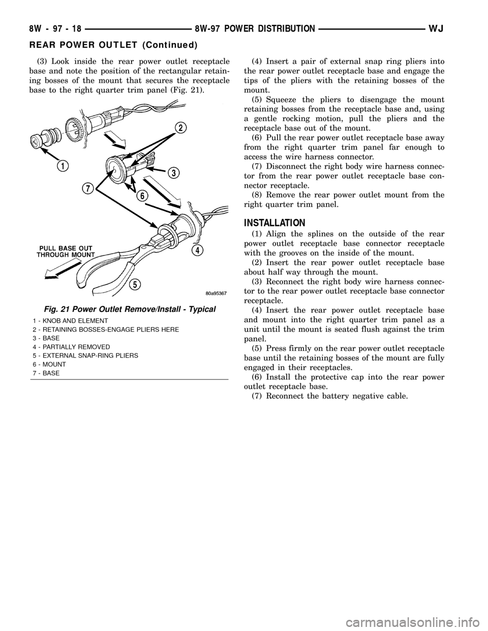
(3) Look inside the rear power outlet receptacle
base and note the position of the rectangular retain-
ing bosses of the mount that secures the receptacle
base to the right quarter trim panel (Fig. 21).(4) Insert a pair of external snap ring pliers into
the rear power outlet receptacle base and engage the
tips of the pliers with the retaining bosses of the
mount.
(5) Squeeze the pliers to disengage the mount
retaining bosses from the receptacle base and, using
a gentle rocking motion, pull the pliers and the
receptacle base out of the mount.
(6) Pull the rear power outlet receptacle base away
from the right quarter trim panel far enough to
access the wire harness connector.
(7) Disconnect the right body wire harness connec-
tor from the rear power outlet receptacle base con-
nector receptacle.
(8) Remove the rear power outlet mount from the
right quarter trim panel.
INSTALLATION
(1) Align the splines on the outside of the rear
power outlet receptacle base connector receptacle
with the grooves on the inside of the mount.
(2) Insert the rear power outlet receptacle base
about half way through the mount.
(3) Reconnect the right body wire harness connec-
tor to the rear power outlet receptacle base connector
receptacle.
(4) Insert the rear power outlet receptacle base
and mount into the right quarter trim panel as a
unit until the mount is seated flush against the trim
panel.
(5) Press firmly on the rear power outlet receptacle
base until the retaining bosses of the mount are fully
engaged in their receptacles.
(6) Install the protective cap into the rear power
outlet receptacle base.
(7) Reconnect the battery negative cable.
Fig. 21 Power Outlet Remove/Install - Typical
1 - KNOB AND ELEMENT
2 - RETAINING BOSSES-ENGAGE PLIERS HERE
3 - BASE
4 - PARTIALLY REMOVED
5 - EXTERNAL SNAP-RING PLIERS
6 - MOUNT
7 - BASE
8W - 97 - 18 8W-97 POWER DISTRIBUTIONWJ
REAR POWER OUTLET (Continued)
Page 1254 of 2199
CAUTION: DO NOT use engine or transmission oil,
mineral spirits, or kerosene.
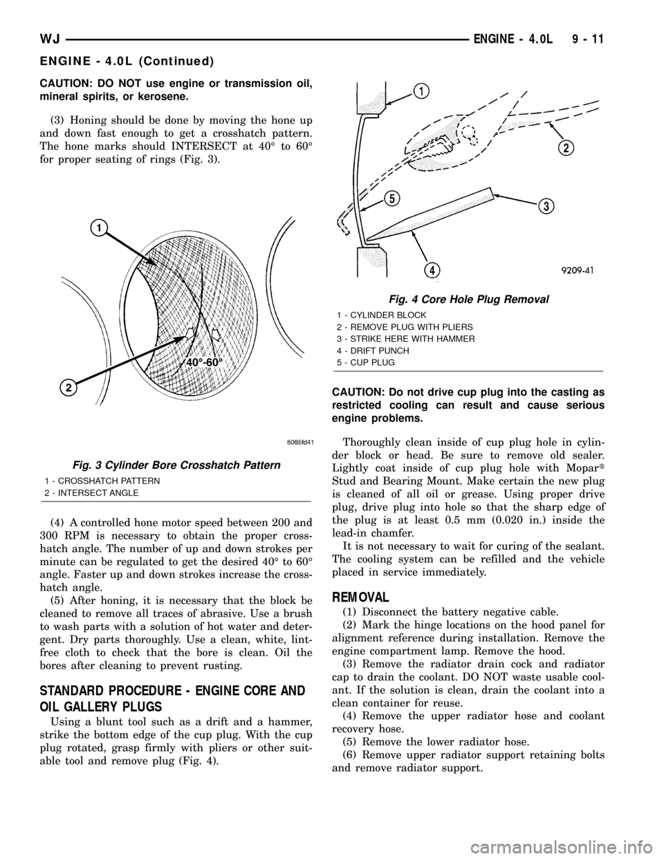
(3) Honing should be done by moving the hone up
and down fast enough to get a crosshatch pattern.
The hone marks should INTERSECT at 40É to 60É
for proper seating of rings (Fig. 3).
(4) A controlled hone motor speed between 200 and
300 RPM is necessary to obtain the proper cross-
hatch angle. The number of up and down strokes per
minute can be regulated to get the desired 40É to 60É
angle. Faster up and down strokes increase the cross-
hatch angle.
(5) After honing, it is necessary that the block be
cleaned to remove all traces of abrasive. Use a brush
to wash parts with a solution of hot water and deter-
gent. Dry parts thoroughly. Use a clean, white, lint-
free cloth to check that the bore is clean. Oil the
bores after cleaning to prevent rusting.
STANDARD PROCEDURE - ENGINE CORE AND
OIL GALLERY PLUGS
Using a blunt tool such as a drift and a hammer,
strike the bottom edge of the cup plug. With the cup
plug rotated, grasp firmly with pliers or other suit-
able tool and remove plug (Fig. 4).CAUTION: Do not drive cup plug into the casting as
restricted cooling can result and cause serious
engine problems.
Thoroughly clean inside of cup plug hole in cylin-
der block or head. Be sure to remove old sealer.
Lightly coat inside of cup plug hole with Mopart
Stud and Bearing Mount. Make certain the new plug
is cleaned of all oil or grease. Using proper drive
plug, drive plug into hole so that the sharp edge of
the plug is at least 0.5 mm (0.020 in.) inside the
lead-in chamfer.
It is not necessary to wait for curing of the sealant.
The cooling system can be refilled and the vehicle
placed in service immediately.
REMOVAL
(1) Disconnect the battery negative cable.
(2) Mark the hinge locations on the hood panel for
alignment reference during installation. Remove the
engine compartment lamp. Remove the hood.
(3) Remove the radiator drain cock and radiator
cap to drain the coolant. DO NOT waste usable cool-
ant. If the solution is clean, drain the coolant into a
clean container for reuse.
(4) Remove the upper radiator hose and coolant
recovery hose.
(5) Remove the lower radiator hose.
(6) Remove upper radiator support retaining bolts
and remove radiator support.
Fig. 3 Cylinder Bore Crosshatch Pattern
1 - CROSSHATCH PATTERN
2 - INTERSECT ANGLE
Fig. 4 Core Hole Plug Removal
1 - CYLINDER BLOCK
2 - REMOVE PLUG WITH PLIERS
3 - STRIKE HERE WITH HAMMER
4 - DRIFT PUNCH
5 - CUP PLUG
WJENGINE - 4.0L 9 - 11
ENGINE - 4.0L (Continued)