2002 JEEP GRAND CHEROKEE intake manifold
[x] Cancel search: intake manifoldPage 1331 of 2199
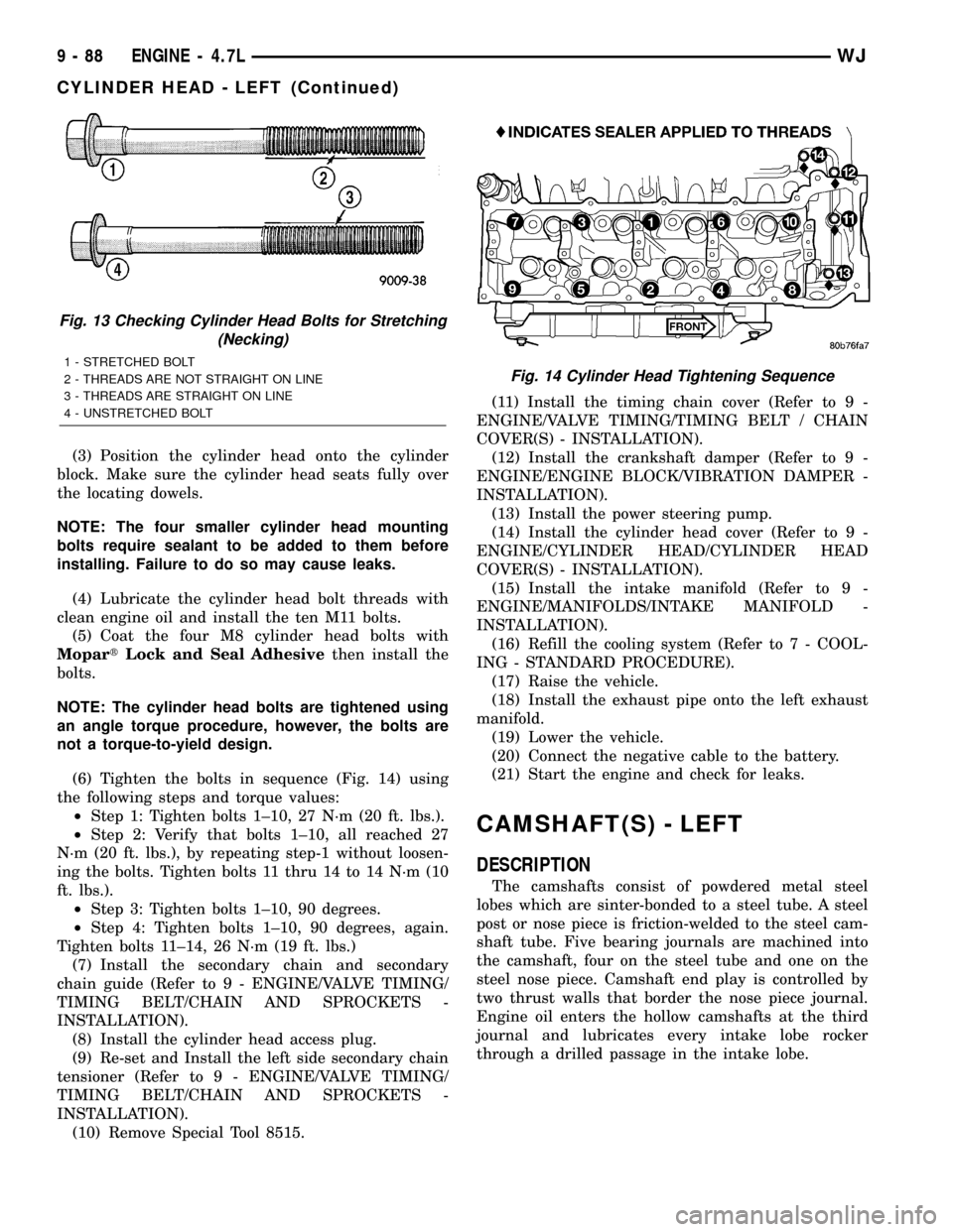
(3) Position the cylinder head onto the cylinder
block. Make sure the cylinder head seats fully over
the locating dowels.
NOTE: The four smaller cylinder head mounting
bolts require sealant to be added to them before
installing. Failure to do so may cause leaks.
(4) Lubricate the cylinder head bolt threads with
clean engine oil and install the ten M11 bolts.
(5) Coat the four M8 cylinder head bolts with
MopartLock and Seal Adhesivethen install the
bolts.
NOTE: The cylinder head bolts are tightened using
an angle torque procedure, however, the bolts are
not a torque-to-yield design.
(6) Tighten the bolts in sequence (Fig. 14) using
the following steps and torque values:
²Step 1: Tighten bolts 1±10, 27 N´m (20 ft. lbs.).
²Step 2: Verify that bolts 1±10, all reached 27
N´m (20 ft. lbs.), by repeating step-1 without loosen-
ing the bolts. Tighten bolts 11 thru 14 to 14 N´m (10
ft. lbs.).
²Step 3: Tighten bolts 1±10, 90 degrees.
²Step 4: Tighten bolts 1±10, 90 degrees, again.
Tighten bolts 11±14, 26 N´m (19 ft. lbs.)
(7) Install the secondary chain and secondary
chain guide (Refer to 9 - ENGINE/VALVE TIMING/
TIMING BELT/CHAIN AND SPROCKETS -
INSTALLATION).
(8) Install the cylinder head access plug.
(9) Re-set and Install the left side secondary chain
tensioner (Refer to 9 - ENGINE/VALVE TIMING/
TIMING BELT/CHAIN AND SPROCKETS -
INSTALLATION).
(10) Remove Special Tool 8515.(11) Install the timing chain cover (Refer to 9 -
ENGINE/VALVE TIMING/TIMING BELT / CHAIN
COVER(S) - INSTALLATION).
(12) Install the crankshaft damper (Refer to 9 -
ENGINE/ENGINE BLOCK/VIBRATION DAMPER -
INSTALLATION).
(13) Install the power steering pump.
(14) Install the cylinder head cover (Refer to 9 -
ENGINE/CYLINDER HEAD/CYLINDER HEAD
COVER(S) - INSTALLATION).
(15) Install the intake manifold (Refer to 9 -
ENGINE/MANIFOLDS/INTAKE MANIFOLD -
INSTALLATION).
(16) Refill the cooling system (Refer to 7 - COOL-
ING - STANDARD PROCEDURE).
(17) Raise the vehicle.
(18) Install the exhaust pipe onto the left exhaust
manifold.
(19) Lower the vehicle.
(20) Connect the negative cable to the battery.
(21) Start the engine and check for leaks.
CAMSHAFT(S) - LEFT
DESCRIPTION
The camshafts consist of powdered metal steel
lobes which are sinter-bonded to a steel tube. A steel
post or nose piece is friction-welded to the steel cam-
shaft tube. Five bearing journals are machined into
the camshaft, four on the steel tube and one on the
steel nose piece. Camshaft end play is controlled by
two thrust walls that border the nose piece journal.
Engine oil enters the hollow camshafts at the third
journal and lubricates every intake lobe rocker
through a drilled passage in the intake lobe.
Fig. 13 Checking Cylinder Head Bolts for Stretching
(Necking)
1 - STRETCHED BOLT
2 - THREADS ARE NOT STRAIGHT ON LINE
3 - THREADS ARE STRAIGHT ON LINE
4 - UNSTRETCHED BOLTFig. 14 Cylinder Head Tightening Sequence
9 - 88 ENGINE - 4.7LWJ
CYLINDER HEAD - LEFT (Continued)
Page 1341 of 2199
VISUAL TEST METHOD
With the engine cool, remove the coolant pressure
cap. Start the engine and allow it to warm up until
thermostat opens.
If a large combustion/compression pressure leak
exists, bubbles will be visible in the coolant.
COOLING SYSTEM TESTER METHOD
WARNING: WITH COOLING SYSTEM TESTER IN
PLACE, PRESSURE WILL BUILD UP FAST. EXCES-
SIVE PRESSURE BUILT UP, BY CONTINUOUS
ENGINE OPERATION, MUST BE RELEASED TO A
SAFE PRESSURE POINT. NEVER PERMIT PRES-
SURE TO EXCEED 138 kPa (20 psi).
Install Cooling System Tester 7700 or equivalent to
pressure cap neck. Start the engine and observe the
tester's pressure gauge. If gauge pulsates with every
power stroke of a cylinder a combustion pressure
leak is evident.
CHEMICAL TEST METHOD
Combustion leaks into the cooling system can also
be checked by using Bloc-Chek Kit C-3685-A or
equivalent. Perform test following the procedures
supplied with the tool kit.
DIAGNOSIS AND TESTING - HYDRAULIC LASH
ADJUSTER
A tappet-like noise may be produced from several
items. Check the following items.
(1) Engine oil level too high or too low. This may
cause aerated oil to enter the adjusters and cause
them to be spongy.
(2) Insufficient running time after rebuilding cylin-
der head. Low speed running up to 1 hour may be
required.
(3) Turn engine off and let set for a few minutes
before restarting. Repeat this several times after
engine has reached normal operating temperature.
(4) Low oil pressure.
(5) The oil restrictor in cylinder head gasket or the
oil passage to the cylinder head is plugged with
debris.
(6) Air ingested into oil due to broken or cracked
oil pump pick up.
(7) Worn valve guides.
(8) Rocker arm ears contacting valve spring
retainer.
(9) Rocker arm loose, adjuster stuck or at maxi-
mum extension and still leaves lash in the system.
(10) Oil leak or excessive cam bore wear in cylin-
der head.
(11) Faulty lash adjuster.a. Check lash adjusters for sponginess while
installed in cylinder head and cam on camshaft at
base circle. Depress part of rocker arm over adjuster.
Normal adjusters should feel very firm. Spongy
adjusters can be bottomed out easily.
b. Remove suspected lash adjusters, and replace.
c. Before installation, make sure adjusters are at
least partially full of oil. This can be verified by little
or no plunger travel when lash adjuster is depressed.
REMOVAL
(1) Disconnect battery negitive cable.
(2) Raise the vehicle on a hoist.
(3) Disconnect the exhaust pipe at the right side
exhaust manifold.
(4) Drain the engine coolant (Refer to 7 - COOL-
ING - STANDARD PROCEDURE).
(5) Lower the vehicle.
(6) Remove the intake manifold (Refer to 9 -
ENGINE/MANIFOLDS/INTAKE MANIFOLD -
REMOVAL).
(7) Remove the cylinder head cover (Refer to 9 -
ENGINE/CYLINDER HEAD/CYLINDER HEAD
COVER(S) - REMOVAL).
(8) Remove oil fill housing from cylinder head.
(9) Remove accessory drive belt (Refer to 7 -
COOLING/ACCESSORY DRIVE/DRIVE BELTS -
REMOVAL).
(10) Rotate the crankshaft until the damper tim-
ing mark is aligned with TDC indicator mark (Fig.
9).
(11) Verify the V8 mark on the camshaft sprocket
is at the 12 o'clock position (Fig. 11). Rotate the
crankshaft one turn if necessary.
(12) Remove the crankshaft damper (Refer to 9 -
ENGINE/ENGINE BLOCK/VIBRATION DAMPER -
REMOVAL).
(13) Remove the timing chain cover (Refer to 9 -
ENGINE/VALVE TIMING/TIMING BELT / CHAIN
COVER(S) - REMOVAL).
(14) Lock the secondary timing chains to the idler
sprocket using Special Tool 8515 (Fig. 10).
NOTE: Mark the secondary timing chain prior to
removal to aid in installation.
(15) Mark the secondary timing chain, one link on
each side of the V8 mark on the camshaft drive gear
(Fig. 11).
(16) Remove the right side secondary chain ten-
sioner (Refer to 9 - ENGINE/VALVE TIMING/TIM-
ING BELT/CHAIN AND SPROCKETS - REMOVAL).
(17) Remove the cylinder head access plug (Fig.
29).
(18) Remove the right side secondary chain guide
(Refer to 9 - ENGINE/VALVE TIMING/TIMING
BELT/CHAIN AND SPROCKETS - REMOVAL).
9 - 98 ENGINE - 4.7LWJ
CYLINDER HEAD - RIGHT (Continued)
Page 1343 of 2199
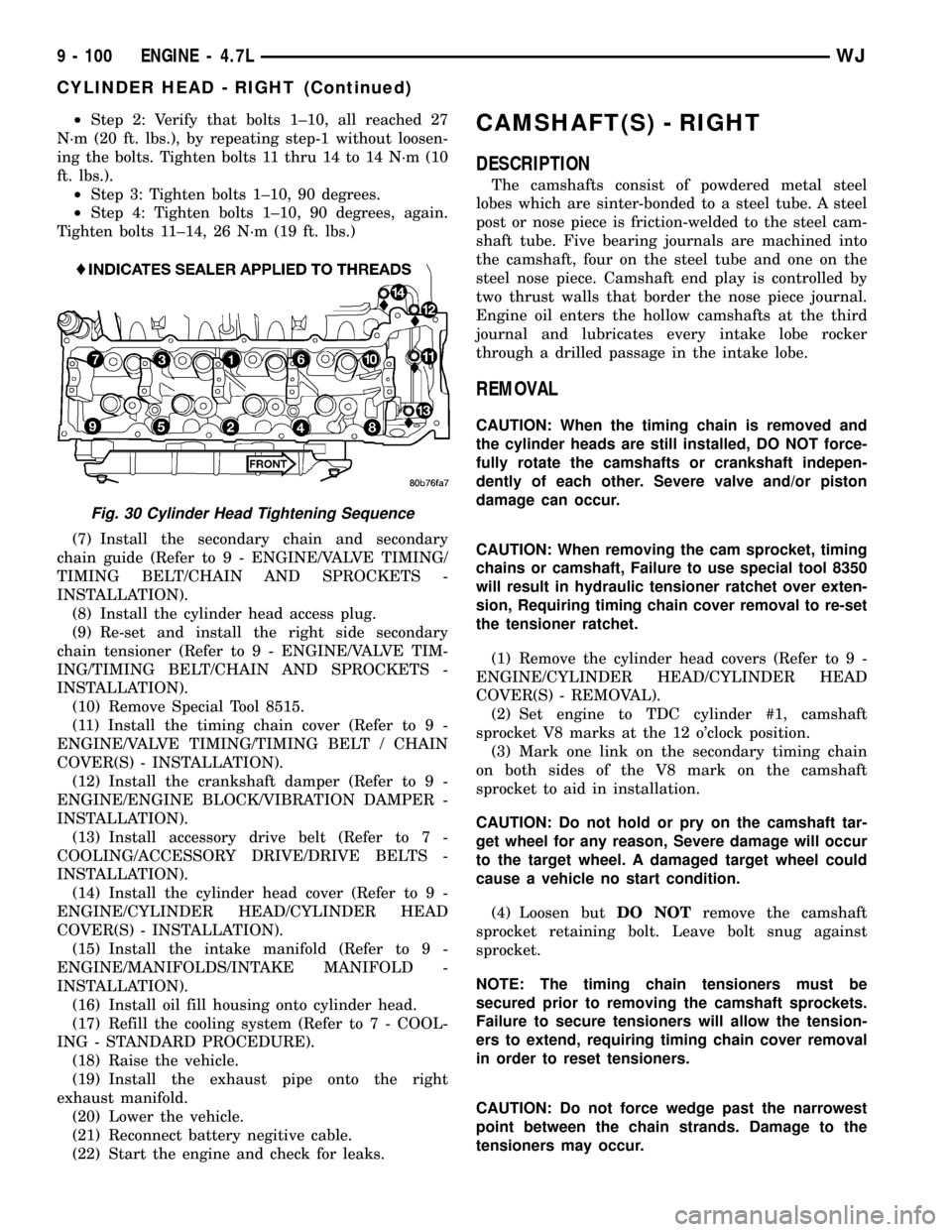
²Step 2: Verify that bolts 1±10, all reached 27
N´m (20 ft. lbs.), by repeating step-1 without loosen-
ing the bolts. Tighten bolts 11 thru 14 to 14 N´m (10
ft. lbs.).
²Step 3: Tighten bolts 1±10, 90 degrees.
²Step 4: Tighten bolts 1±10, 90 degrees, again.
Tighten bolts 11±14, 26 N´m (19 ft. lbs.)
(7) Install the secondary chain and secondary
chain guide (Refer to 9 - ENGINE/VALVE TIMING/
TIMING BELT/CHAIN AND SPROCKETS -
INSTALLATION).
(8) Install the cylinder head access plug.
(9) Re-set and install the right side secondary
chain tensioner (Refer to 9 - ENGINE/VALVE TIM-
ING/TIMING BELT/CHAIN AND SPROCKETS -
INSTALLATION).
(10) Remove Special Tool 8515.
(11) Install the timing chain cover (Refer to 9 -
ENGINE/VALVE TIMING/TIMING BELT / CHAIN
COVER(S) - INSTALLATION).
(12) Install the crankshaft damper (Refer to 9 -
ENGINE/ENGINE BLOCK/VIBRATION DAMPER -
INSTALLATION).
(13) Install accessory drive belt (Refer to 7 -
COOLING/ACCESSORY DRIVE/DRIVE BELTS -
INSTALLATION).
(14) Install the cylinder head cover (Refer to 9 -
ENGINE/CYLINDER HEAD/CYLINDER HEAD
COVER(S) - INSTALLATION).
(15) Install the intake manifold (Refer to 9 -
ENGINE/MANIFOLDS/INTAKE MANIFOLD -
INSTALLATION).
(16) Install oil fill housing onto cylinder head.
(17) Refill the cooling system (Refer to 7 - COOL-
ING - STANDARD PROCEDURE).
(18) Raise the vehicle.
(19) Install the exhaust pipe onto the right
exhaust manifold.
(20) Lower the vehicle.
(21) Reconnect battery negitive cable.
(22) Start the engine and check for leaks.CAMSHAFT(S) - RIGHT
DESCRIPTION
The camshafts consist of powdered metal steel
lobes which are sinter-bonded to a steel tube. A steel
post or nose piece is friction-welded to the steel cam-
shaft tube. Five bearing journals are machined into
the camshaft, four on the steel tube and one on the
steel nose piece. Camshaft end play is controlled by
two thrust walls that border the nose piece journal.
Engine oil enters the hollow camshafts at the third
journal and lubricates every intake lobe rocker
through a drilled passage in the intake lobe.
REMOVAL
CAUTION: When the timing chain is removed and
the cylinder heads are still installed, DO NOT force-
fully rotate the camshafts or crankshaft indepen-
dently of each other. Severe valve and/or piston
damage can occur.
CAUTION: When removing the cam sprocket, timing
chains or camshaft, Failure to use special tool 8350
will result in hydraulic tensioner ratchet over exten-
sion, Requiring timing chain cover removal to re-set
the tensioner ratchet.
(1) Remove the cylinder head covers (Refer to 9 -
ENGINE/CYLINDER HEAD/CYLINDER HEAD
COVER(S) - REMOVAL).
(2) Set engine to TDC cylinder #1, camshaft
sprocket V8 marks at the 12 o'clock position.
(3) Mark one link on the secondary timing chain
on both sides of the V8 mark on the camshaft
sprocket to aid in installation.
CAUTION: Do not hold or pry on the camshaft tar-
get wheel for any reason, Severe damage will occur
to the target wheel. A damaged target wheel could
cause a vehicle no start condition.
(4) Loosen butDO NOTremove the camshaft
sprocket retaining bolt. Leave bolt snug against
sprocket.
NOTE: The timing chain tensioners must be
secured prior to removing the camshaft sprockets.
Failure to secure tensioners will allow the tension-
ers to extend, requiring timing chain cover removal
in order to reset tensioners.
CAUTION: Do not force wedge past the narrowest
point between the chain strands. Damage to the
tensioners may occur.
Fig. 30 Cylinder Head Tightening Sequence
9 - 100 ENGINE - 4.7LWJ
CYLINDER HEAD - RIGHT (Continued)
Page 1379 of 2199
INTAKE MANIFOLD
DESCRIPTION
The intake manifold is made of a composite mate-
rial and features long runners which maximizes low
end torque. The intake manifold uses single plane
sealing which consist of eight individual press in
place port gaskets to prevent leaks. Eight studs and
two bolts are used to fasten the intake to the head.
DIAGNOSIS AND TESTINGÐINTAKE
MANIFOLD LEAKAGE
An intake manifold air leak is characterized by
lower than normal manifold vacuum. Also, one or
more cylinders may not be functioning.
WARNING: USE EXTREME CAUTION WHEN THE
ENGINE IS OPERATING. DO NOT STAND IN A
DIRECT LINE WITH THE FAN. DO NOT PUT YOUR
HANDS NEAR THE PULLEYS, BELTS OR THE FAN.
DO NOT WEAR LOOSE CLOTHING.
(1) Start the engine.
(2) Spray a small stream of water at the suspected
leak area.
(3) If a change in RPM is observed the area of the
suspected leak has been found.
(4) Repair as required.
REMOVAL
(1) Disconnect negative cable from battery.
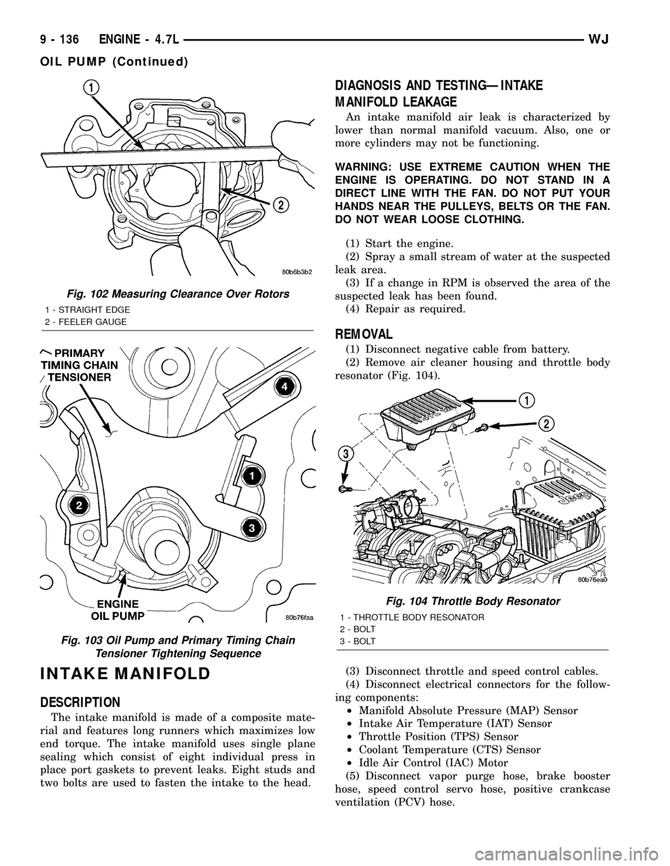
(2) Remove air cleaner housing and throttle body
resonator (Fig. 104).
(3) Disconnect throttle and speed control cables.
(4) Disconnect electrical connectors for the follow-
ing components:
²Manifold Absolute Pressure (MAP) Sensor
²Intake Air Temperature (IAT) Sensor
²Throttle Position (TPS) Sensor
²Coolant Temperature (CTS) Sensor
²Idle Air Control (IAC) Motor
(5) Disconnect vapor purge hose, brake booster
hose, speed control servo hose, positive crankcase
ventilation (PCV) hose.
Fig. 102 Measuring Clearance Over Rotors
1 - STRAIGHT EDGE
2 - FEELER GAUGE
Fig. 103 Oil Pump and Primary Timing Chain
Tensioner Tightening Sequence
Fig. 104 Throttle Body Resonator
1 - THROTTLE BODY RESONATOR
2 - BOLT
3 - BOLT
9 - 136 ENGINE - 4.7LWJ
OIL PUMP (Continued)
Page 1380 of 2199
(6) Remove accessory drive belt (Refer to 7 -
COOLING/ACCESSORY DRIVE/DRIVE BELTS -
REMOVAL).
(7) Disconnect generator electrical connections.
(8) Unbolt the generator and move it away from
the intake manifold for clearance.
(9) Disconnect air conditioning compressor electri-
cal connections.
(10) Unbolt the air conditioning compressor and
move it away from the intake manifold for clearance.
(11) Disconnect left and right radio suppressor
straps.
(12) Disconnect and remove ignition coil towers
(Refer to 8 - ELECTRICAL/IGNITION CONTROL/
IGNITION COIL - REMOVAL).
(13) Remove top oil dipstick tube retaining bolt
and ground strap.
(14) Bleed pressure from fuel system (Refer to 14 -
FUEL SYSTEM/FUEL DELIVERY - STANDARD
PROCEDURE).
(15) Remove fuel rail (Refer to 14 - FUEL SYS-
TEM/FUEL DELIVERY/FUEL RAIL - REMOVAL).
(16) Remove throttle body assembly and mounting
bracket.
(17) Drain cooling system below coolant tempera-
ture level (Refer to 7 - COOLING - STANDARD
PROCEDURE).
(18) Remove coolant temperature sensor (Refer to
7 - COOLING/ENGINE/ENGINE COOLANT TEMP
SENSOR - REMOVAL).
(19) Remove cowl to hood seal. (Refer to 23 -
BODY/WEATHERSTRIP/SEALS/COWL WEATHER-
STRIP - REMOVAL).
(20) Remove right side engine lifting stud.
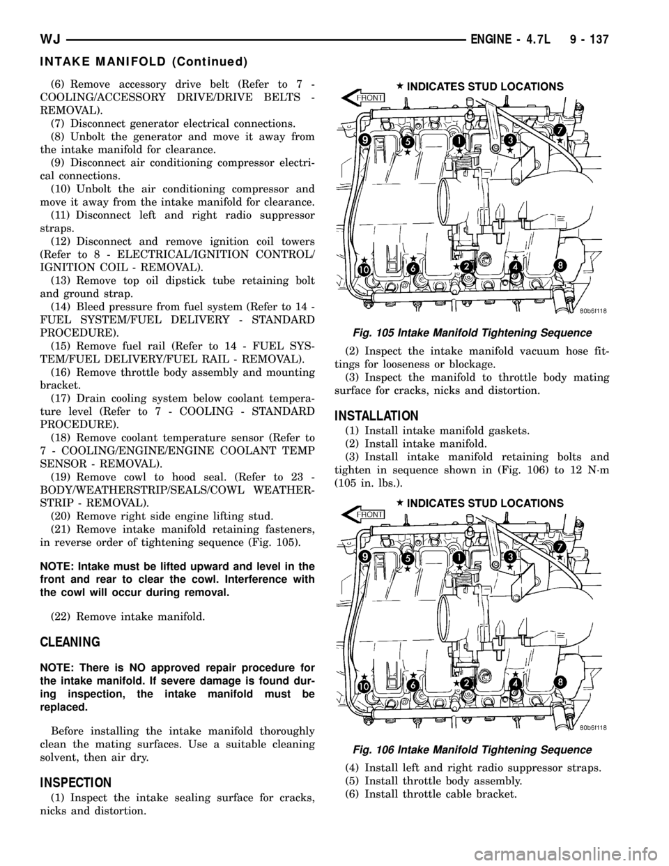
(21) Remove intake manifold retaining fasteners,
in reverse order of tightening sequence (Fig. 105).
NOTE: Intake must be lifted upward and level in the
front and rear to clear the cowl. Interference with
the cowl will occur during removal.
(22) Remove intake manifold.
CLEANING
NOTE: There is NO approved repair procedure for
the intake manifold. If severe damage is found dur-
ing inspection, the intake manifold must be
replaced.
Before installing the intake manifold thoroughly
clean the mating surfaces. Use a suitable cleaning
solvent, then air dry.
INSPECTION
(1) Inspect the intake sealing surface for cracks,
nicks and distortion.(2) Inspect the intake manifold vacuum hose fit-
tings for looseness or blockage.
(3) Inspect the manifold to throttle body mating
surface for cracks, nicks and distortion.
INSTALLATION
(1) Install intake manifold gaskets.
(2) Install intake manifold.
(3) Install intake manifold retaining bolts and
tighten in sequence shown in (Fig. 106) to 12 N´m
(105 in. lbs.).
(4) Install left and right radio suppressor straps.
(5) Install throttle body assembly.
(6) Install throttle cable bracket.
Fig. 105 Intake Manifold Tightening Sequence
Fig. 106 Intake Manifold Tightening Sequence
WJENGINE - 4.7L 9 - 137
INTAKE MANIFOLD (Continued)
Page 1381 of 2199

(7) Connect throttle cable and speed control cable
to throttle body.
(8) Install fuel rail (Refer to 14 - FUEL SYSTEM/
FUEL DELIVERY/FUEL RAIL - INSTALLATION).
(9) Install ignition coil towers (Refer to 8 - ELEC-
TRICAL/IGNITION CONTROL/IGNITION COIL -
INSTALLATION).
(10) Install coolant temperature sensor (Refer to 7
- COOLING/ENGINE/ENGINE COOLANT TEMP
SENSOR - INSTALLATION).
(11) Connect electrical connectors for the following
components:
²Manifold Absolute Pressure (MAP) Sensor
²Intake Air Temperature (IAT) Sensor
²Throttle Position (TPS) Sensor
²Coolant Temperature (CTS) Sensor
²Idle Air Control (IAC) Motor
²Ignition coil towers
²Fuel injectors
(12) Install top oil dipstick tube retaining bolt and
ground strap.
(13) Install right side engine lifting stud.
(14) Install generator including electrical connec-
tions (Refer to 8 - ELECTRICAL/CHARGING/GEN-
ERATOR - INSTALLATION).
(15) Connect Vapor purge hose, Brake booster
hose, Speed control servo hose, Positive crankcase
ventilation (PCV) hose.
(16) Install air conditioning compressor including
electrical connections.
(17) Fill cooling system (Refer to 7 - COOLING -
STANDARD PROCEDURE).
(18) Install accessory drive belt (Refer to 7 -
COOLING/ACCESSORY DRIVE/DRIVE BELTS -
INSTALLATION).
(19) Install cowl to hood seal (Refer to 23 - BODY/
WEATHERSTRIP/SEALS/COWL WEATHERSTRIP -
INSTALLATION).
(20) Install air cleaner housing and throttle body
resonator. Tighten resonator bolts 4.5 N´m (40 in.
lbs.).
(21) Connect negative cable to battery.
EXHAUST MANIFOLD - LEFT
DESCRIPTION
The exhaust manifolds are log style with a pat-
ented flow enhancing design to maximize perfor-
mance. The exhaust manifolds are made of high
silicon molybdenum cast iron. A perforated core
graphite exhaust manifold gasket is used to improve
sealing to the cylinder head. The exhaust manifolds
are covered by a three layer laminated heat shield
for thermal protection and noise reduction. The heat
shields are fastened with a torque prevailing nutthat is backed off slightly to allow for the thermal
expansion of the exhaust manifold.
REMOVAL
(1) Disconnect negative cable for battery.
(2) Hoist vehicle.
(3) Disconnect exhaust pipe at manifold.
(4) Lower vehicle.
(5) Remove air cleaner housing and tube.
(6) Remove the front two exhaust heat shield
retaining fasteners. Raise vehicle and remove the
fasteners at rear of heat shield.
(7) Remove heat shield (Fig. 107).
(8) Lower vehicle and remove the upper exhaust
manifold retaining bolts (Fig. 107).
(9) Raise vehicle and remove the lower exhaust
manifold retaining bolts (Fig. 107).
(10) Remove exhaust manifold and gasket (Fig.
107). Manifold is removed from below the engine
compartment.
CLEANING
(1) Clean the exhaust manifold using a suitable
cleaning solvent, then allow to air dry.
(2) Clean all gasket residue from the manifold
mating surface.
INSPECTION
(1) Inspect the exhaust manifold for cracks in the
mating surface and at every mounting bolt hole.
(2) Using a straight edge and a feeler gauge, check
the mating surface for warp and twist.
(3) Inspect the manifold to exhaust pipe mating
surface for cracks, gouges, or other damage that
would prevent sealing.
INSTALLATION
(1) Install exhaust manifold and gasket from below
engine compartment.
(2) Install lower exhaust manifold fasteners (Fig.
107). DO NOT tighten until all fasteners are in
place.
(3) Lower vehicle and install upper exhaust mani-
fold fasteners (Fig. 107). Tighten all manifold bolts
starting at center and working outward to 25 N´m
(18 ft. lbs.).
CAUTION: Over tightening heat shield fasteners,
may cause shield to distort and/or crack.
(4) Install exhaust manifold heat shield (Fig. 107).
Tighten fasteners to 8 N´m (72 in. lbs.), then loosen
45 degrees.
(5) Install air cleaner housing and tube.
(6) Connect exhaust pipe to manifold.
(7) Connect negative cable to battery.
9 - 138 ENGINE - 4.7LWJ
INTAKE MANIFOLD (Continued)
Page 1384 of 2199
INSPECTION
(1) Inspect the exhaust manifold for cracks in the
mating surface and at every mounting bolt hole.
(2) Using a straight edge and a feeler gauge, check
the mating surface for warp and twist.
(3) Inspect the manifold to exhaust pipe mating
surface for cracks, gouges, or other damage that
would prevent sealing.
INSTALLATION
(1) Install exhaust manifold and gasket from below
engine compartment.
(2) Install lower exhaust manifold fasteners. DO
NOT tighten until all fasteners are in place.
(3) Lower vehicle and install upper exhaust mani-
fold fasteners. Tighten all manifold bolts starting at
center and working outward to 25 N´m (18 ft. lbs.).
CAUTION: Over tightening heat shield fasteners,
may cause shield to distort and/or crack.
(4) Install exhaust manifold heat shield. Tighten
fasteners to 8 N´m (72 in. lbs.), then loosen 45
degrees.
(5) Install starter and fasteners.
(6) Connect exhaust pipe to manifold.
(7) Connect heater hoses at engine.
(8) Install fastener attaching A/C accumulator.
(9) Install A/C compressor and fasteners.
(10) Install accessory drive belt (Refer to 7 -
COOLING/ACCESSORY DRIVE/DRIVE BELTS -
INSTALLATION).
(11) Install washer bottle and battery tray assem-
bly.
(12) Install PDC.
(13) Install battery and connect cables.
(14) Fill cooling system (Refer to 7 - COOLING -
STANDARD PROCEDURE).
VALVE TIMING
DESCRIPTION - TIMING DRIVE SYSTEM
The timing drive system has been designed to pro-
vide quiet performance and reliability to support a
non-free wheelingengine. Specifically the intake
valves are non-free wheeling and can be easily dam-
aged with forceful engine rotation if camshaft-to-
crankshaft timing is incorrect. The timing drive
system consists of a primary chain and two second-
ary timing chain drives (Fig. 109).
OPERATION - TIMING DRIVE SYSTEM
The primary timing chain is a single inverted tooth
type. The primary chain drives the large fifty tooth
idler sprocket directly from a 25 tooth crankshaftsprocket. Primary chain motion is controlled by a
pivoting leaf spring tensioner arm and a fixed guide.
The arm and the guide both use nylon plastic wear
faces for low friction and long wear. The primary
chain receives oil splash lubrication from the second-
ary chain drive and oil pump leakage. The idler
sprocket assembly connects the primary and second-
ary chain drives. The idler sprocket assembly con-
sists of two integral thirty tooth sprockets and a fifty
tooth sprocket that is splined to the assembly. The
spline joint is a non ± serviceable press fit anti rattle
type. A spiral ring is installed on the outboard side of
the fifty tooth sprocket to prevent spline disengage-
ment. The idler sprocket assembly spins on a station-
ary idler shaft. The idler shaft is press-fit into the
cylinder block. A large washer on the idler shaft bolt
and the rear flange of the idler shaft are used to con-
trol sprocket thrust movement. Pressurized oil is
routed through the center of the idler shaft to pro-
vide lubrication for the two bushings used in the
idler sprocket assembly.
There are two secondary drive chains, both are
inverted tooth type, one to drive the camshaft in each
SOHC cylinder head. There are no shaft speed
changes in the secondary chain drive system. Each
secondary chain drives a thirty tooth cam sprocket
directly from the thirty tooth sprocket on the idler
sprocket assembly. A fixed chain guide and a hydrau-
lic oil damped tensioner are used to maintain tension
in each secondary chain system. The hydraulic ten-
sioners for the secondary chain systems are fed pres-
surized oil from oil reservoir pockets in the block.
Each tensioner also has a mechanical ratchet system
that limits chain slack if the tensioner piston bleeds
down after engine shut down. The tensioner arms
and guides also utilize nylon wear faces for low fric-
tion and long wear. The secondary timing chains
receive lubrication from a small orifice in the ten-
sioners. This orifice is protected from clogging by a
fine mesh screen which is located on the back of the
hydraulic tensioners.
STANDARD PROCEDURE
STANDARD PROCEDURE - ENGINE TIMING -
VERIFICATION
CAUTION: The 4.7L is a non free-wheeling design
engine. Therefore, correct engine timing is critical.
NOTE: Components referred to as left hand or right
hand are as viewed from the drivers position inside
the vehicle.
WJENGINE - 4.7L 9 - 141
EXHAUST MANIFOLD - RIGHT (Continued)
Page 1434 of 2199
(8) Connect fuel return and pressure lines to fuel
pump module fittings (Fig. 16). Refer to Quick-Con-
nect Fittings.
(9) Install fuel tank. Refer to Fuel Tank Installa-
tion.
FUEL RAIL
DESCRIPTION
DESCRIPTION - 4.7L
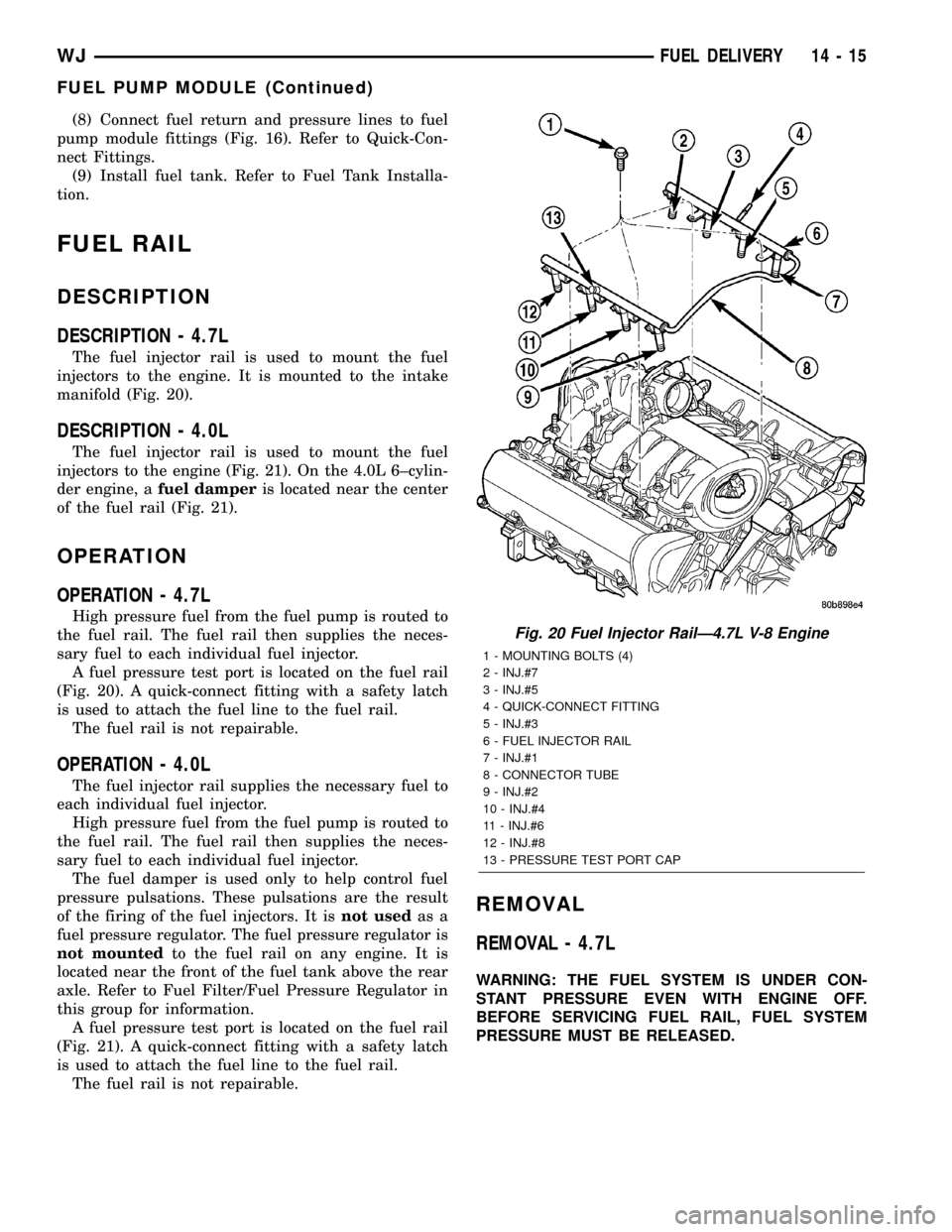
The fuel injector rail is used to mount the fuel
injectors to the engine. It is mounted to the intake
manifold (Fig. 20).
DESCRIPTION - 4.0L
The fuel injector rail is used to mount the fuel
injectors to the engine (Fig. 21). On the 4.0L 6±cylin-
der engine, afuel damperis located near the center
of the fuel rail (Fig. 21).
OPERATION
OPERATION - 4.7L
High pressure fuel from the fuel pump is routed to
the fuel rail. The fuel rail then supplies the neces-
sary fuel to each individual fuel injector.
A fuel pressure test port is located on the fuel rail
(Fig. 20). A quick-connect fitting with a safety latch
is used to attach the fuel line to the fuel rail.
The fuel rail is not repairable.
OPERATION - 4.0L
The fuel injector rail supplies the necessary fuel to
each individual fuel injector.
High pressure fuel from the fuel pump is routed to
the fuel rail. The fuel rail then supplies the neces-
sary fuel to each individual fuel injector.
The fuel damper is used only to help control fuel
pressure pulsations. These pulsations are the result
of the firing of the fuel injectors. It isnot usedas a
fuel pressure regulator. The fuel pressure regulator is
not mountedto the fuel rail on any engine. It is
located near the front of the fuel tank above the rear
axle. Refer to Fuel Filter/Fuel Pressure Regulator in
this group for information.
A fuel pressure test port is located on the fuel rail
(Fig. 21). A quick-connect fitting with a safety latch
is used to attach the fuel line to the fuel rail.
The fuel rail is not repairable.
REMOVAL
REMOVAL - 4.7L
WARNING: THE FUEL SYSTEM IS UNDER CON-
STANT PRESSURE EVEN WITH ENGINE OFF.
BEFORE SERVICING FUEL RAIL, FUEL SYSTEM
PRESSURE MUST BE RELEASED.
Fig. 20 Fuel Injector RailÐ4.7L V-8 Engine
1 - MOUNTING BOLTS (4)
2 - INJ.#7
3 - INJ.#5
4 - QUICK-CONNECT FITTING
5 - INJ.#3
6 - FUEL INJECTOR RAIL
7 - INJ.#1
8 - CONNECTOR TUBE
9 - INJ.#2
10 - INJ.#4
11 - INJ.#6
12 - INJ.#8
13 - PRESSURE TEST PORT CAP
WJFUEL DELIVERY 14 - 15
FUEL PUMP MODULE (Continued)