2002 JEEP GRAND CHEROKEE Gasket leak
[x] Cancel search: Gasket leakPage 1538 of 2199

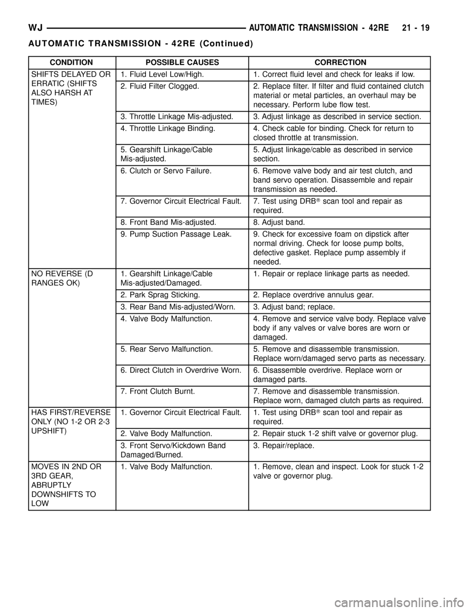
CONDITION POSSIBLE CAUSES CORRECTION
SHIFTS DELAYED OR
ERRATIC (SHIFTS
ALSO HARSH AT
TIMES)1. Fluid Level Low/High. 1. Correct fluid level and check for leaks if low.
2. Fluid Filter Clogged. 2. Replace filter. If filter and fluid contained clutch
material or metal particles, an overhaul may be
necessary. Perform lube flow test.
3. Throttle Linkage Mis-adjusted. 3. Adjust linkage as described in service section.
4. Throttle Linkage Binding. 4. Check cable for binding. Check for return to
closed throttle at transmission.
5. Gearshift Linkage/Cable
Mis-adjusted.5. Adjust linkage/cable as described in service
section.
6. Clutch or Servo Failure. 6. Remove valve body and air test clutch, and
band servo operation. Disassemble and repair
transmission as needed.
7. Governor Circuit Electrical Fault. 7. Test using DRBTscan tool and repair as
required.
8. Front Band Mis-adjusted. 8. Adjust band.
9. Pump Suction Passage Leak. 9. Check for excessive foam on dipstick after
normal driving. Check for loose pump bolts,
defective gasket. Replace pump assembly if
needed.
NO REVERSE (D
RANGES OK)1. Gearshift Linkage/Cable
Mis-adjusted/Damaged.1. Repair or replace linkage parts as needed.
2. Park Sprag Sticking. 2. Replace overdrive annulus gear.
3. Rear Band Mis-adjusted/Worn. 3. Adjust band; replace.
4. Valve Body Malfunction. 4. Remove and service valve body. Replace valve
body if any valves or valve bores are worn or
damaged.
5. Rear Servo Malfunction. 5. Remove and disassemble transmission.
Replace worn/damaged servo parts as necessary.
6. Direct Clutch in Overdrive Worn. 6. Disassemble overdrive. Replace worn or
damaged parts.
7. Front Clutch Burnt. 7. Remove and disassemble transmission.
Replace worn, damaged clutch parts as required.
HAS FIRST/REVERSE
ONLY (NO 1-2 OR 2-3
UPSHIFT)1. Governor Circuit Electrical Fault. 1. Test using DRBTscan tool and repair as
required.
2. Valve Body Malfunction. 2. Repair stuck 1-2 shift valve or governor plug.
3. Front Servo/Kickdown Band
Damaged/Burned.3. Repair/replace.
MOVES IN 2ND OR
3RD GEAR,
ABRUPTLY
DOWNSHIFTS TO
LOW1. Valve Body Malfunction. 1. Remove, clean and inspect. Look for stuck 1-2
valve or governor plug.
WJAUTOMATIC TRANSMISSION - 42RE 21 - 19
AUTOMATIC TRANSMISSION - 42RE (Continued)
Page 1540 of 2199

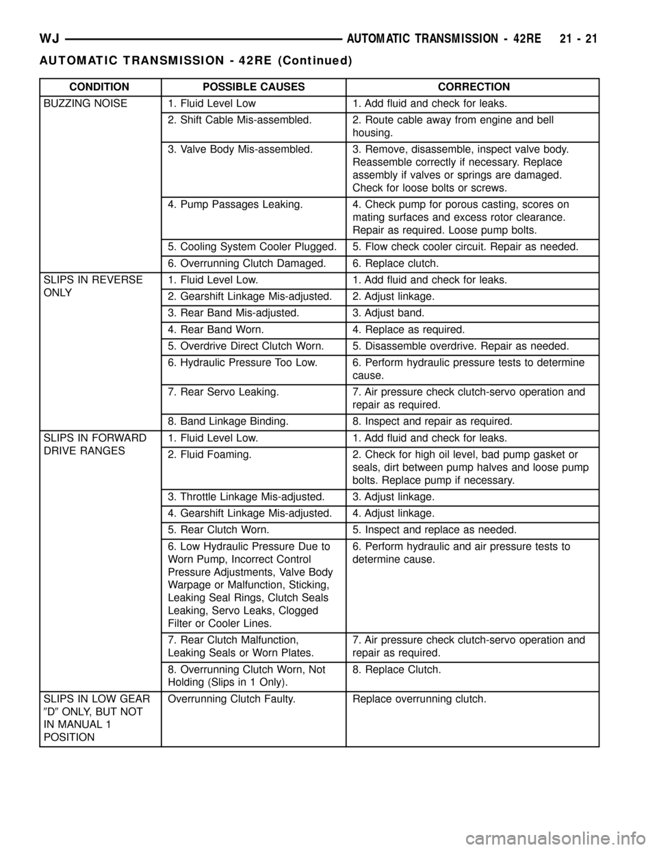
CONDITION POSSIBLE CAUSES CORRECTION
BUZZING NOISE 1. Fluid Level Low 1. Add fluid and check for leaks.
2. Shift Cable Mis-assembled. 2. Route cable away from engine and bell
housing.
3. Valve Body Mis-assembled. 3. Remove, disassemble, inspect valve body.
Reassemble correctly if necessary. Replace
assembly if valves or springs are damaged.
Check for loose bolts or screws.
4. Pump Passages Leaking. 4. Check pump for porous casting, scores on
mating surfaces and excess rotor clearance.
Repair as required. Loose pump bolts.
5. Cooling System Cooler Plugged. 5. Flow check cooler circuit. Repair as needed.
6. Overrunning Clutch Damaged. 6. Replace clutch.
SLIPS IN REVERSE
ONLY1. Fluid Level Low. 1. Add fluid and check for leaks.
2. Gearshift Linkage Mis-adjusted. 2. Adjust linkage.
3. Rear Band Mis-adjusted. 3. Adjust band.
4. Rear Band Worn. 4. Replace as required.
5. Overdrive Direct Clutch Worn. 5. Disassemble overdrive. Repair as needed.
6. Hydraulic Pressure Too Low. 6. Perform hydraulic pressure tests to determine
cause.
7. Rear Servo Leaking. 7. Air pressure check clutch-servo operation and
repair as required.
8. Band Linkage Binding. 8. Inspect and repair as required.
SLIPS IN FORWARD
DRIVE RANGES1. Fluid Level Low. 1. Add fluid and check for leaks.
2. Fluid Foaming. 2. Check for high oil level, bad pump gasket or
seals, dirt between pump halves and loose pump
bolts. Replace pump if necessary.
3. Throttle Linkage Mis-adjusted. 3. Adjust linkage.
4. Gearshift Linkage Mis-adjusted. 4. Adjust linkage.
5. Rear Clutch Worn. 5. Inspect and replace as needed.
6. Low Hydraulic Pressure Due to
Worn Pump, Incorrect Control
Pressure Adjustments, Valve Body
Warpage or Malfunction, Sticking,
Leaking Seal Rings, Clutch Seals
Leaking, Servo Leaks, Clogged
Filter or Cooler Lines.6. Perform hydraulic and air pressure tests to
determine cause.
7. Rear Clutch Malfunction,
Leaking Seals or Worn Plates.7. Air pressure check clutch-servo operation and
repair as required.
8. Overrunning Clutch Worn, Not
Holding (Slips in 1 Only).8. Replace Clutch.
SLIPS IN LOW GEAR
9D9ONLY, BUT NOT
IN MANUAL 1
POSITIONOverrunning Clutch Faulty. Replace overrunning clutch.
WJAUTOMATIC TRANSMISSION - 42RE 21 - 21
AUTOMATIC TRANSMISSION - 42RE (Continued)
Page 1545 of 2199

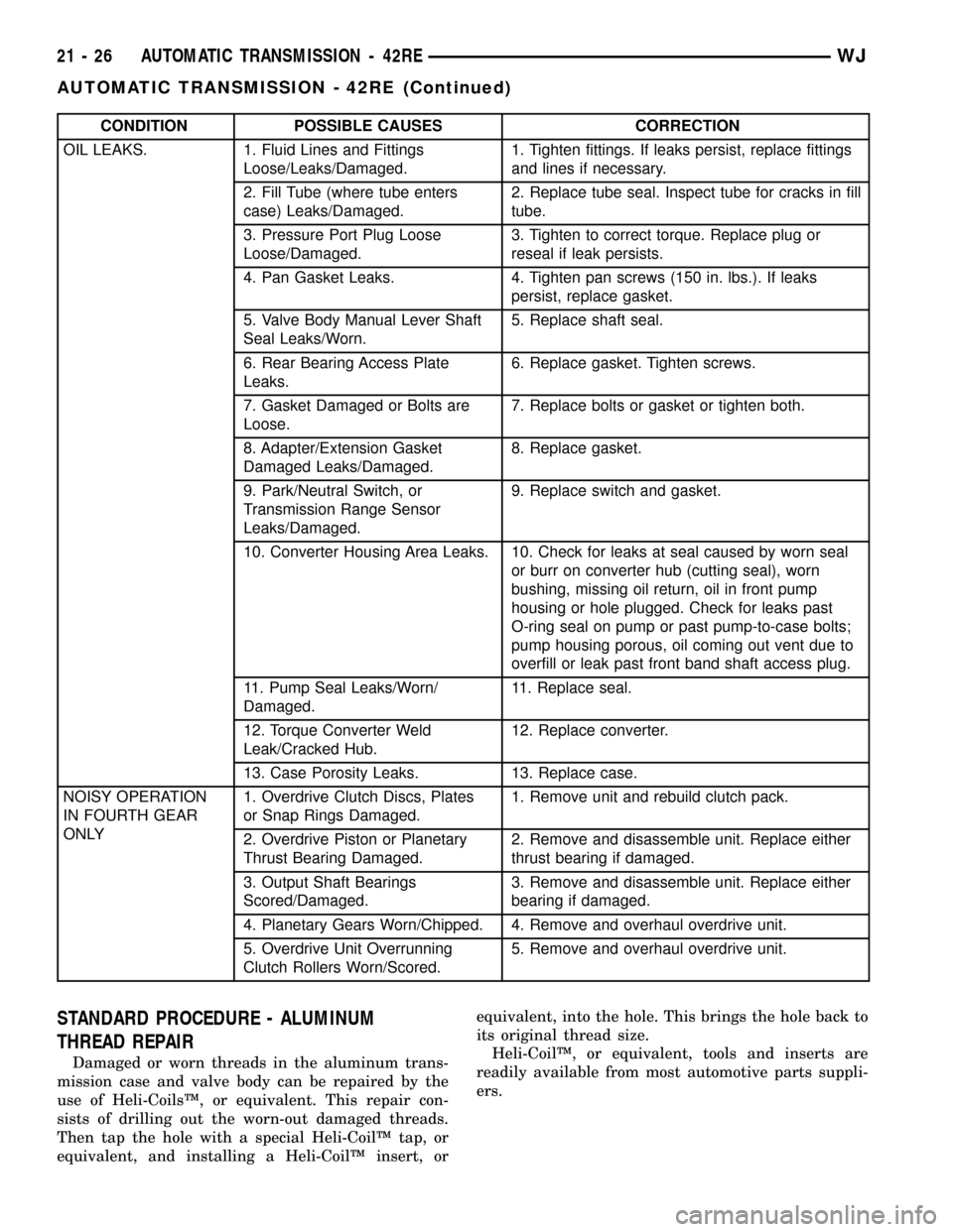
CONDITION POSSIBLE CAUSES CORRECTION
OIL LEAKS. 1. Fluid Lines and Fittings
Loose/Leaks/Damaged.1. Tighten fittings. If leaks persist, replace fittings
and lines if necessary.
2. Fill Tube (where tube enters
case) Leaks/Damaged.2. Replace tube seal. Inspect tube for cracks in fill
tube.
3. Pressure Port Plug Loose
Loose/Damaged.3. Tighten to correct torque. Replace plug or
reseal if leak persists.
4. Pan Gasket Leaks. 4. Tighten pan screws (150 in. lbs.). If leaks
persist, replace gasket.
5. Valve Body Manual Lever Shaft
Seal Leaks/Worn.5. Replace shaft seal.
6. Rear Bearing Access Plate
Leaks.6. Replace gasket. Tighten screws.
7. Gasket Damaged or Bolts are
Loose.7. Replace bolts or gasket or tighten both.
8. Adapter/Extension Gasket
Damaged Leaks/Damaged.8. Replace gasket.
9. Park/Neutral Switch, or
Transmission Range Sensor
Leaks/Damaged.9. Replace switch and gasket.
10. Converter Housing Area Leaks. 10. Check for leaks at seal caused by worn seal
or burr on converter hub (cutting seal), worn
bushing, missing oil return, oil in front pump
housing or hole plugged. Check for leaks past
O-ring seal on pump or past pump-to-case bolts;
pump housing porous, oil coming out vent due to
overfill or leak past front band shaft access plug.
11. Pump Seal Leaks/Worn/
Damaged.11. Replace seal.
12. Torque Converter Weld
Leak/Cracked Hub.12. Replace converter.
13. Case Porosity Leaks. 13. Replace case.
NOISY OPERATION
IN FOURTH GEAR
ONLY1. Overdrive Clutch Discs, Plates
or Snap Rings Damaged.1. Remove unit and rebuild clutch pack.
2. Overdrive Piston or Planetary
Thrust Bearing Damaged.2. Remove and disassemble unit. Replace either
thrust bearing if damaged.
3. Output Shaft Bearings
Scored/Damaged.3. Remove and disassemble unit. Replace either
bearing if damaged.
4. Planetary Gears Worn/Chipped. 4. Remove and overhaul overdrive unit.
5. Overdrive Unit Overrunning
Clutch Rollers Worn/Scored.5. Remove and overhaul overdrive unit.
STANDARD PROCEDURE - ALUMINUM
THREAD REPAIR
Damaged or worn threads in the aluminum trans-
mission case and valve body can be repaired by the
use of Heli-CoilsŸ, or equivalent. This repair con-
sists of drilling out the worn-out damaged threads.
Then tap the hole with a special Heli-CoilŸ tap, or
equivalent, and installing a Heli-CoilŸ insert, orequivalent, into the hole. This brings the hole back to
its original thread size.
Heli-CoilŸ, or equivalent, tools and inserts are
readily available from most automotive parts suppli-
ers.
21 - 26 AUTOMATIC TRANSMISSION - 42REWJ
AUTOMATIC TRANSMISSION - 42RE (Continued)
Page 1560 of 2199

(32) Install valve body as follows:
(a) Align and carefully insert park rod into pawl.
Rod will make click noise as it enters pawl. Move
rod slightly to check engagement.
(b) Align and seat valve body on case. Be sure
manual lever shaft and overdrive connector are
fully seated in case. Also be sure valve body wiring
is not pinched or kinked.
(c) Install and start all valve body attaching
bolts by hand. Then tighten bolts evenly, in a diag-
onal pattern to 12 N´m (105 in. lbs.) torque. Do not
overtighten valve body bolts. This could result in
distortion and cross leakage after installation.
CAUTION: It is possible for the park rod to displace
into a cavity just above the pawl sprag during
installation. Make sure the rod is actually engaged
in the pawl and has not displaced into the cavity.
(33) Install new filter on valve body. Tighten filter
screws to 4 N´m (35 in. lbs.).
(34) Adjust front and rear bands.
(35) Install seal on park/neutral position switch.
Then install and tighten switch to 34 N´m (25 ft.
lbs.).
(36) Install magnet in oil pan. Magnet goes on
small protrusion at corner of pan.
(37) Position new oil pan gasket on case and
install oil pan. Tighten pan bolts to 17 N´m (13 ft.
lbs.).
(38) Install new valve body manual shaft seal in
case (Fig. 60). Lubricate seal lip and manual shaft
with petroleum jelly. Start seal over shaft and into
case. Seat seal with 15/16 inch, deep well socket.
(39) Install throttle valve and shift selector levers
on valve body manual lever shaft.INSTALLATION
(1) Check torque converter hub and hub drive
notches for sharp edges burrs, scratches, or nicks.
Polish the hub and notches with 320/400 grit paper
and crocus cloth if necessary. The hub must be
smooth to avoid damaging pump seal during installa-
tion.
(2) Lubricate oil pump seal lip with transmission
fluid.
(3) Align converter and oil pump.
(4) Carefully insert converter in oil pump. Then
rotate converter back and forth until fully seated in
pump gears.
(5) Check converter seating with steel scale and
straightedge (Fig. 61). Surface of converter lugs
should be 1/2 in. to rear of straightedge when con-
verter is fully seated.
(6) Temporarily secure converter with C-clamp.
(7) Position transmission on jack and secure it
with chains.
(8) Check condition of converter driveplate.
Replace the plate if cracked, distorted or damaged.
Also be sure transmission dowel pins are seated in
engine block and protrude far enough to hold trans-
mission in alignment.
(9) Apply a light coating of MopartHigh Temp
grease to the torque converter hub pocket in the rear
of the crankshaft
(10) Raise transmission and align converter with
drive plate and converter housing with engine block.
Fig. 60 Installing Manual Lever Shaft Seal
1 - 15/1688SOCKET
2 - SEAL
Fig. 61 Checking Torque Converter Seating - Typical
1 - SCALE
2 - STRAIGHTEDGE
WJAUTOMATIC TRANSMISSION - 42RE 21 - 41
AUTOMATIC TRANSMISSION - 42RE (Continued)
Page 1590 of 2199

PROCEDURE TWO
(1) Start engine and apply parking brake.
(2) Shift the transmission into DRIVE for approxi-
mately 2 seconds.
(3) Shift the transmission into REVERSE for
approximately 2 seconds.
(4) Shift the transmission into PARK.
(5) Hook up DRBtscan tool and select engine.
(6) Select sensors.
(7) Read the transmission temperature value.
(8) Compare the fluid temperature value with the
figure. (Fig. 88)
(9) Adjust transmission fluid level shown on the
dipstick according to the figure.NOTE: After adding any fluid to the transmission,
wait a minimum of 2 minutes for the oil to fully
drain from the fill tube into the transmission before
rechecking the fluid level.
(10) Check transmission for leaks.
STANDARD PROCEDURE - FLUID AND FILTER
REPLACEMENT
For proper service intervals (Refer to LUBRICA-
TION & MAINTENANCE/MAINTENANCE SCHED-
ULES - DESCRIPTION). The service fluid fill after a
filter change is approximately 3.8 liters (4.0 quarts).
REMOVAL
(1) Hoist and support vehicle on safety stands.
(2) Place a large diameter shallow drain pan
beneath the transmission pan.
(3) Remove bolts holding front and sides of pan to
transmission (Fig. 89).
(4) Loosen bolts holding rear of pan to transmis-
sion.
(5) Slowly separate front of pan and gasket away
from transmission allowing the fluid to drain into
drain pan.
(6) Hold up pan and remove remaining bolt hold-
ing pan to transmission.
Fig. 88 42/44RE Fluid Fill Graph
Fig. 87 Dipstick Fluid Level Marks - Typical
1 - DIPSTICK
2 - MAXIMUM CORRECT FLUID LEVEL
3 - ACCEPTABLE FLUID LEVEL
WJAUTOMATIC TRANSMISSION - 42RE 21 - 71
FLUID AND FILTER (Continued)
Page 1849 of 2199

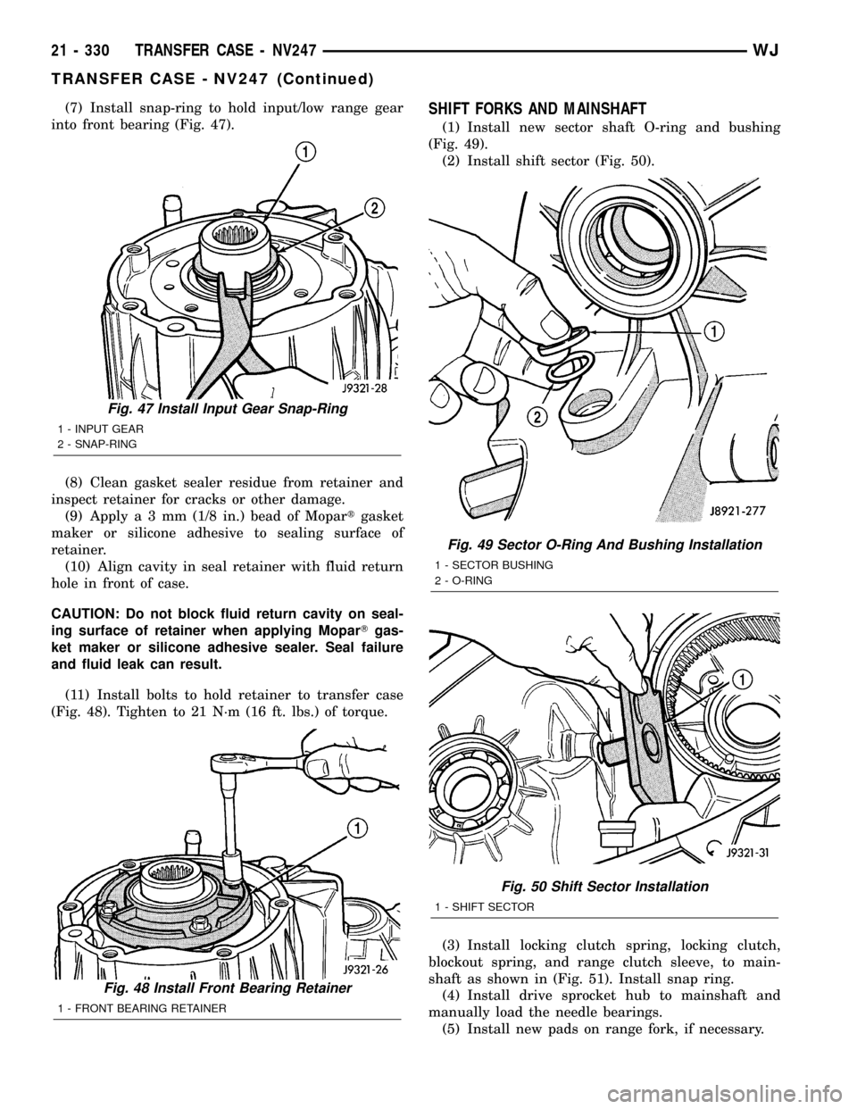
(7) Install snap-ring to hold input/low range gear
into front bearing (Fig. 47).
(8) Clean gasket sealer residue from retainer and
inspect retainer for cracks or other damage.
(9) Applya3mm(1/8 in.) bead of Mopartgasket
maker or silicone adhesive to sealing surface of
retainer.
(10) Align cavity in seal retainer with fluid return
hole in front of case.
CAUTION: Do not block fluid return cavity on seal-
ing surface of retainer when applying MoparTgas-
ket maker or silicone adhesive sealer. Seal failure
and fluid leak can result.
(11) Install bolts to hold retainer to transfer case
(Fig. 48). Tighten to 21 N´m (16 ft. lbs.) of torque.SHIFT FORKS AND MAINSHAFT
(1) Install new sector shaft O-ring and bushing
(Fig. 49).
(2) Install shift sector (Fig. 50).
(3) Install locking clutch spring, locking clutch,
blockout spring, and range clutch sleeve, to main-
shaft as shown in (Fig. 51). Install snap ring.
(4) Install drive sprocket hub to mainshaft and
manually load the needle bearings.
(5) Install new pads on range fork, if necessary.
Fig. 47 Install Input Gear Snap-Ring
1 - INPUT GEAR
2 - SNAP-RING
Fig. 48 Install Front Bearing Retainer
1 - FRONT BEARING RETAINER
Fig. 49 Sector O-Ring And Bushing Installation
1 - SECTOR BUSHING
2 - O-RING
Fig. 50 Shift Sector Installation
1 - SHIFT SECTOR
21 - 330 TRANSFER CASE - NV247WJ
TRANSFER CASE - NV247 (Continued)
Page 1875 of 2199

leak area. If the hose cannot be positioned without
being held, have someone help do the water test.
Some water leaks must be tested for a considerable
length of time to become apparent. When a leak
appears, find the highest point of the water track or
drop. The highest point usually will show the point of
entry. After leak point has been found, repair the
leak and water test to verify that the leak has
stopped.
Locating the entry point of water that is leaking
into a cavity between panels can be difficult. The
trapped water may splash or run from the cavity,
often at a distance from the entry point. Most water
leaks of this type become apparent after accelerating,
stopping, turning, or when on an incline.
MIRROR INSPECTION METHOD
When a leak point area is visually obstructed, use
a suitable mirror to gain visual access. A mirror can
also be used to deflect light to a limited-access area
to assist in locating a leak point.
BRIGHT LIGHT LEAK TEST METHOD
Some water leaks in the luggage compartment can
be detected without water testing. Position the vehi-
cle in a brightly lit area. From inside the darkened
luggage compartment inspect around seals and body
seams. If necessary, have a helper direct a drop light
over the suspected leak areas around the luggage
compartment. If light is visible through a normally
sealed location, water could enter through the open-
ing.
PRESSURIZED LEAK TEST METHOD
When a water leak into the passenger compart-
ment cannot be detected by water testing, pressurize
the passenger compartment and soap test exterior of
the vehicle. To pressurize the passenger compart-
ment, close all doors and windows, start engine, and
set heater control to high blower in HEAT position. If
engine can not be started, connect a charger to the
battery to ensure adequate voltage to the blower.
With interior pressurized, apply dish detergent solu-
tion to suspected leak area on the exterior of the
vehicle. Apply detergent solution with spray device or
soft bristle brush. If soap bubbles occur at a body
seam, joint, seal or gasket, the leak entry point could
be at that location.
WIND NOISE
Wind noise is the result of most air leaks. Air leaks
can be caused by poor sealing, improper body compo-
nent alignment, body seam porosity, or missing plugs
in the engine compartment or door hinge pillar areas.
All body sealing points should be airtight in normal
driving conditions. Moving sealing surfaces will notalways seal airtight under all conditions. At times,
side glass or door seals will allow wind noise to be
noticed in the passenger compartment during high
cross winds. Over compensating on door or glass
adjustments to stop wind noise that occurs under
severe conditions can cause premature seal wear and
excessive closing or latching effort. After a repair pro-
cedure has been performed, test vehicle to verify
noise has stopped before returning vehicle to use.
Wind noise can also be caused by improperly fitted
exterior moldings or body ornamentation. Loose
moldings can flutter, creating a buzzing or chattering
noise. An open cavity or protruding edge can create a
whistling or howling noise. Inspect the exterior of the
vehicle to verify that these conditions do not exist.
VISUAL INSPECTION BEFORE TESTS
Verify that floor and body plugs are in place and
body components are aligned and sealed. If compo-
nent alignment or sealing is necessary, refer to the
appropriate section of this group for proper proce-
dures.
ROAD TESTING WIND NOISE
(1) Drive the vehicle to verify the general location
of the wind noise.
(2) Apply 50 mm (2 in.) masking tape in 150 mm
(6 in.) lengths along weatherstrips, weld seams or
moldings. After each length is applied, drive the vehi-
cle. If noise goes away after a piece of tape is applied,
remove tape, locate, and repair defect.
POSSIBLE CAUSE OF WIND NOISE
²Moldings standing away from body surface can
catch wind and whistle.
²Gaps in sealed areas behind overhanging body
flanges can cause wind-rushing sounds.
²Misaligned movable components.
²Missing or improperly installed plugs in pillars.
²Weld burn through holes.
STANDARD PROCEDURE
STANDARD PROCEDURE - BODY LUBRICATION
All mechanisms and linkages should be lubricated
when necessary. This will maintain ease of operation
and provide protection against rust and excessive
wear. The weatherstrip seals should be lubricated to
prolong their life as well as to improve door sealing.
All applicable exterior and interior vehicle operat-
ing mechanisms should be inspected and cleaned.
Pivot/sliding contact areas on the mechanisms should
then be lubricated.
(1) When necessary, lubricate the operating mech-
anisms with the specified lubricants.
23 - 2 BODYWJ
BODY (Continued)
Page 2130 of 2199

CAUTION
CAUTION
CAUTION: Liquid refrigerant is corrosive to metal
surfaces. Follow the operating instructions supplied
with the service equipment being used.
Never add R-12 to a refrigerant system designed to
use R-134a. Damage to the system will result.
R-12 refrigerant oil must not be mixed with R-134a
refrigerant oil. They are not compatible.
Do not use R-12 equipment or parts on the R-134a
system. Damage to the system will result.
Do not overcharge the refrigerant system. This will
cause excessive compressor head pressure and
can cause noise and system failure.
Recover the refrigerant before opening any fitting
or connection. Open the fittings with caution, even
after the system has been discharged. Never open
or loosen a connection before recovering the refrig-
erant.
The refrigerant system must always be evacuated
before charging.
Do not open the refrigerant system or uncap a
replacement component until you are ready to ser-
vice the system. This will prevent contamination in
the system.
Before disconnecting a component, clean the out-
side of the fittings thoroughly to prevent contami-
nation from entering the refrigerant system.
Immediately after disconnecting a component from
the refrigerant system, seal the open fittings with a
cap or plug.
Before connecting an open refrigerant fitting,
always install a new seal or gasket. Coat the fitting
and seal with clean refrigerant oil before connect-
ing.
Do not remove the sealing caps from a replacement
component until it is to be installed.
When installing a refrigerant line, avoid sharp
bends that may restrict refrigerant flow. Position the
refrigerant lines away from exhaust system compo-
nents or any sharp edges, which may damage the
line.
Tighten refrigerant fittings only to the specified
torque. The aluminum fittings used in the refriger-
ant system will not tolerate overtightening.
When disconnecting a refrigerant fitting, use a
wrench on both halves of the fitting. This will pre-
vent twisting of the refrigerant lines or tubes.
Refrigerant oil will absorb moisture from the atmo-
sphere if left uncapped. Do not open a container of
refrigerant oil until you are ready to use it. Replace
the cap on the oil container immediately after using.
Store refrigerant oil only in a clean, airtight, and
moisture-free container.Keep service tools and the work area clean. Con-
tamination of the refrigerant system through care-
less work habits must be avoided.REFRIGERANT HOSES/LINES/TUBES
PRECAUTIONS
Kinks or sharp bends in the refrigerant plumbing
will reduce the capacity of the entire system. High
pressures are produced in the system when it is oper-
ating. Extreme care must be exercised to make sure
that all refrigerant system connections are pressure
tight.
A good rule for the flexible hose refrigerant lines is
to keep the radius of all bends at least ten times the
diameter of the hose. Sharp bends will reduce the
flow of refrigerant. The flexible hose lines should be
routed so they are at least 80 millimeters (3 inches)
from the exhaust manifold. It is a good practice to
inspect all flexible refrigerant system hose lines at
least once a year to make sure they are in good con-
dition and properly routed.
There are two types of refrigerant fittings:
²All fittings with O-rings need to be coated with
refrigerant oil before installation. Use only O-rings
that are the correct size and approved for use with
R-134a refrigerant. Failure to do so may result in a
leak.
²Unified plumbing connections with gaskets can-
not be serviced with O-rings. The gaskets are not
reusable and new gaskets do not require lubrication
before installing.
Using the proper tools when making a refrigerant
plumbing connection is very important. Improper
tools or improper use of the tools can damage the
refrigerant fittings. Always use two wrenches when
loosening or tightening tube fittings. Use one wrench
to hold one side of the connection stationary, while
loosening or tightening the other side of the connec-
tion with a second wrench.
The refrigerant must be recovered completely from
the system before opening any fitting or connection.
Open the fittings with caution, even after the refrig-
erant has been recovered. If any pressure is noticed
as a fitting is loosened, tighten the fitting and
recover the refrigerant from the system again.
Do not discharge refrigerant into the atmosphere.
Use an R-134a refrigerant recovery/recycling device
that meets SAE Standard J2210.
The refrigerant system will remain chemically sta-
ble as long as pure, moisture-free R-134a refrigerant
and refrigerant oil is used. Dirt, moisture, or air can
upset this chemical stability. Operational troubles or
serious damage can occur if foreign material is
present in the refrigerant system.
When it is necessary to open the refrigerant sys-
tem, have everything needed to service the system
WJPLUMBING 24 - 53
PLUMBING (Continued)