2002 JEEP GRAND CHEROKEE Index
[x] Cancel search: IndexPage 1415 of 2199
INSTALLATION
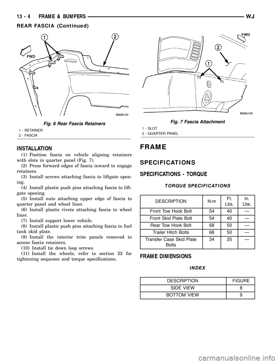
(1) Position fascia on vehicle aligning retainers
with slots in quarter panel (Fig. 7).
(2) Press forward edges of fascia inward to engage
retainers.
(3) Install screws attaching fascia to liftgate open-
ing.
(4) Install plastic push pins attaching fascia to lift-
gate opening.
(5) Install nuts attaching upper edge of fascia to
quarter panel and wheel liner.
(6) Install plastic rivets attaching fascia to wheel
liner.
(7) Install support lower vehicle.
(8) Install plastic push pins attaching fascia to fuel
tank skid plate.
(9) Install the interior trim panels removed to
access fascia retainers.
(10) Install tie down loop screws.
(11) Install the wheels, refer to section 22 for
tightening sequence and torque specifications.
FRAME
SPECIFICATIONS
SPECIFICATIONS - TORQUE
TORQUE SPECIFICATIONS
DESCRIPTION N´mFt.
Lbs.In.
Lbs.
Front Tow Hook Bolt 54 40 Ð
Front Skid Plate Bolt 54 40 Ð
Rear Tow Hook Bolt 68 50 Ð
Trailer Hitch Bolts 68 50 Ð
Transfer Case Skid Plate
Bolts34 25 Ð
FRAME DIMENSIONS
INDEX
DESCRIPTION FIGURE
SIDE VIEW 8
BOTTOM VIEW 9
Fig. 6 Rear Fascia Retainers
1 - RETAINER
2 - FASCIA
Fig. 7 Fascia Attachment
1 - SLOT
2 - QUARTER PANEL
13 - 4 FRAME & BUMPERSWJ
REAR FASCIA (Continued)
Page 1433 of 2199
(2) Drain fuel tank and remove tank. Refer to Fuel
Tank Removal/Installation.
(3) Thoroughly wash and clean area around pump
module to prevent contaminants from entering tank.
(4) Disconnect fuel return and pressure lines from
fuel pump module fittings (Fig. 16). Refer to Quick-
Connect Fittings for procedures.
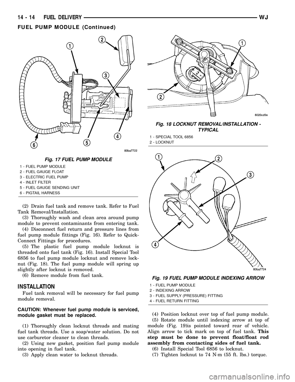
(5) The plastic fuel pump module locknut is
threaded onto fuel tank (Fig. 16). Install Special Tool
6856 to fuel pump module locknut and remove lock-
nut (Fig. 18). The fuel pump module will spring up
slightly after locknut is removed.
(6) Remove module from fuel tank.
INSTALLATION
Fuel tank removal will be necessary for fuel pump
module removal.
CAUTION: Whenever fuel pump module is serviced,
module gasket must be replaced.
(1) Thoroughly clean locknut threads and mating
fuel tank threads. Use a soap/water solution. Do not
use carburetor cleaner to clean threads.
(2) Using new gasket, position fuel pump module
into opening in fuel tank.
(3) Apply clean water to locknut threads.(4) Position locknut over top of fuel pump module.
(5) Rotate module until indexing arrow at top of
module (Fig. 19)is pointed toward rear of vehicle.
Align arrow to tick mark on top of fuel tank.This
step must be done to prevent float/float rod
assembly from contacting sides of fuel tank.
(6) Install Special Tool 6856 to locknut.
(7) Tighten locknut to 74 N´m (55 ft. lbs.) torque.
Fig. 17 FUEL PUMP MODULE
1 - FUEL PUMP MODULE
2 - FUEL GAUGE FLOAT
3 - ELECTRIC FUEL PUMP
4 - INLET FILTER
5 - FUEL GAUGE SENDING UNIT
6 - PIGTAIL HARNESS
Fig. 18 LOCKNUT REMOVAL/INSTALLATION -
TYPICAL
1 - SPECIAL TOOL 6856
2 - LOCKNUT
Fig. 19 FUEL PUMP MODULE INDEXING ARROW
1 - FUEL PUMP MODULE
2 - INDEXING ARROW
3 - FUEL SUPPLY (PRESSURE) FITTING
4 - FUEL RETURN FITTING
14 - 14 FUEL DELIVERYWJ
FUEL PUMP MODULE (Continued)
Page 1439 of 2199
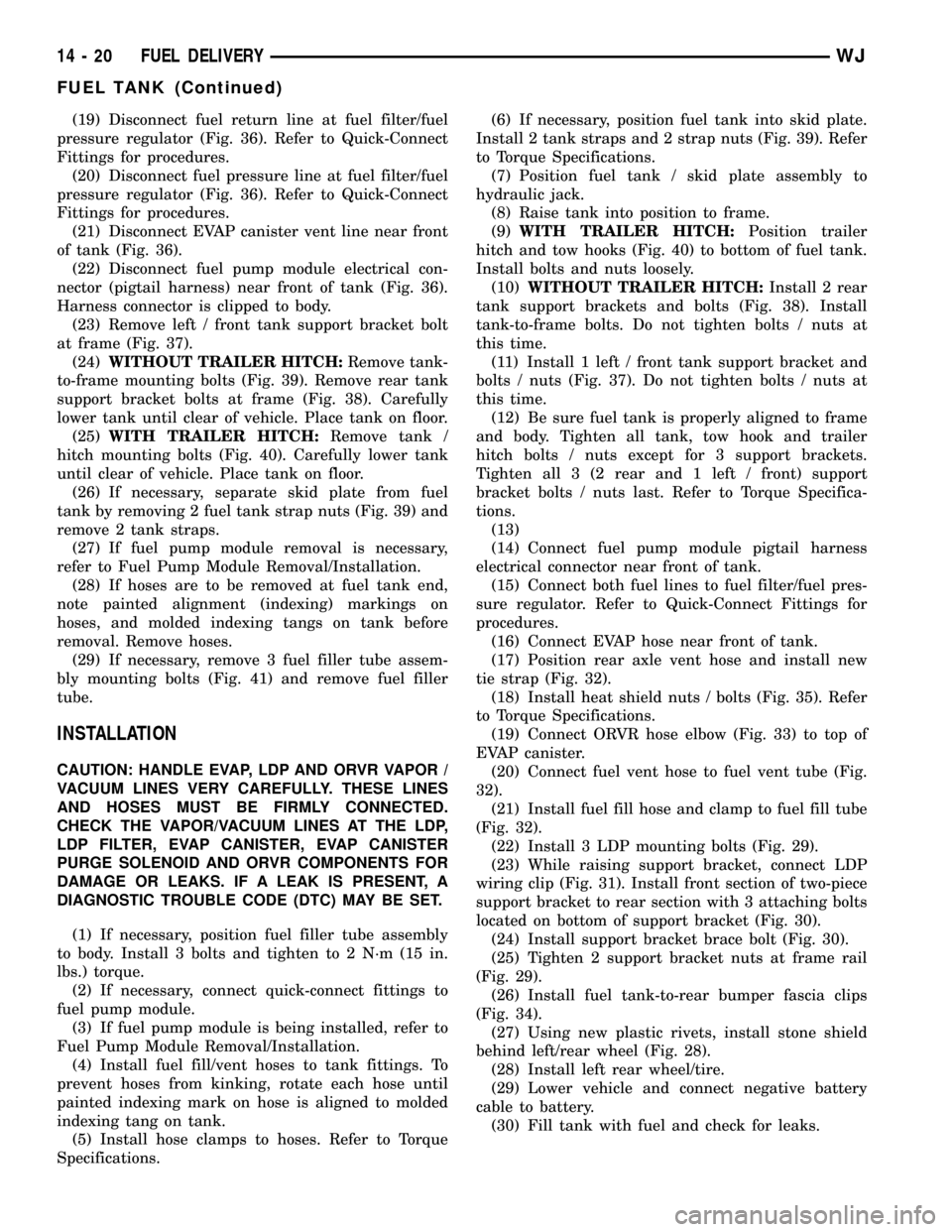
(19) Disconnect fuel return line at fuel filter/fuel
pressure regulator (Fig. 36). Refer to Quick-Connect
Fittings for procedures.
(20) Disconnect fuel pressure line at fuel filter/fuel
pressure regulator (Fig. 36). Refer to Quick-Connect
Fittings for procedures.
(21) Disconnect EVAP canister vent line near front
of tank (Fig. 36).
(22) Disconnect fuel pump module electrical con-
nector (pigtail harness) near front of tank (Fig. 36).
Harness connector is clipped to body.
(23) Remove left / front tank support bracket bolt
at frame (Fig. 37).
(24)WITHOUT TRAILER HITCH:Remove tank-
to-frame mounting bolts (Fig. 39). Remove rear tank
support bracket bolts at frame (Fig. 38). Carefully
lower tank until clear of vehicle. Place tank on floor.
(25)WITH TRAILER HITCH:Remove tank /
hitch mounting bolts (Fig. 40). Carefully lower tank
until clear of vehicle. Place tank on floor.
(26) If necessary, separate skid plate from fuel
tank by removing 2 fuel tank strap nuts (Fig. 39) and
remove 2 tank straps.
(27) If fuel pump module removal is necessary,
refer to Fuel Pump Module Removal/Installation.
(28) If hoses are to be removed at fuel tank end,
note painted alignment (indexing) markings on
hoses, and molded indexing tangs on tank before
removal. Remove hoses.
(29) If necessary, remove 3 fuel filler tube assem-
bly mounting bolts (Fig. 41) and remove fuel filler
tube.
INSTALLATION
CAUTION: HANDLE EVAP, LDP AND ORVR VAPOR /
VACUUM LINES VERY CAREFULLY. THESE LINES
AND HOSES MUST BE FIRMLY CONNECTED.
CHECK THE VAPOR/VACUUM LINES AT THE LDP,
LDP FILTER, EVAP CANISTER, EVAP CANISTER
PURGE SOLENOID AND ORVR COMPONENTS FOR
DAMAGE OR LEAKS. IF A LEAK IS PRESENT, A
DIAGNOSTIC TROUBLE CODE (DTC) MAY BE SET.
(1) If necessary, position fuel filler tube assembly
to body. Install 3 bolts and tighten to 2 N´m (15 in.
lbs.) torque.
(2) If necessary, connect quick-connect fittings to
fuel pump module.
(3) If fuel pump module is being installed, refer to
Fuel Pump Module Removal/Installation.
(4) Install fuel fill/vent hoses to tank fittings. To
prevent hoses from kinking, rotate each hose until
painted indexing mark on hose is aligned to molded
indexing tang on tank.
(5) Install hose clamps to hoses. Refer to Torque
Specifications.(6) If necessary, position fuel tank into skid plate.
Install 2 tank straps and 2 strap nuts (Fig. 39). Refer
to Torque Specifications.
(7) Position fuel tank / skid plate assembly to
hydraulic jack.
(8) Raise tank into position to frame.
(9)WITH TRAILER HITCH:Position trailer
hitch and tow hooks (Fig. 40) to bottom of fuel tank.
Install bolts and nuts loosely.
(10)WITHOUT TRAILER HITCH:Install 2 rear
tank support brackets and bolts (Fig. 38). Install
tank-to-frame bolts. Do not tighten bolts / nuts at
this time.
(11) Install 1 left / front tank support bracket and
bolts / nuts (Fig. 37). Do not tighten bolts / nuts at
this time.
(12) Be sure fuel tank is properly aligned to frame
and body. Tighten all tank, tow hook and trailer
hitch bolts / nuts except for 3 support brackets.
Tighten all 3 (2 rear and 1 left / front) support
bracket bolts / nuts last. Refer to Torque Specifica-
tions.
(13)
(14) Connect fuel pump module pigtail harness
electrical connector near front of tank.
(15) Connect both fuel lines to fuel filter/fuel pres-
sure regulator. Refer to Quick-Connect Fittings for
procedures.
(16) Connect EVAP hose near front of tank.
(17) Position rear axle vent hose and install new
tie strap (Fig. 32).
(18) Install heat shield nuts / bolts (Fig. 35). Refer
to Torque Specifications.
(19) Connect ORVR hose elbow (Fig. 33) to top of
EVAP canister.
(20) Connect fuel vent hose to fuel vent tube (Fig.
32).
(21) Install fuel fill hose and clamp to fuel fill tube
(Fig. 32).
(22) Install 3 LDP mounting bolts (Fig. 29).
(23) While raising support bracket, connect LDP
wiring clip (Fig. 31). Install front section of two-piece
support bracket to rear section with 3 attaching bolts
located on bottom of support bracket (Fig. 30).
(24) Install support bracket brace bolt (Fig. 30).
(25) Tighten 2 support bracket nuts at frame rail
(Fig. 29).
(26) Install fuel tank-to-rear bumper fascia clips
(Fig. 34).
(27) Using new plastic rivets, install stone shield
behind left/rear wheel (Fig. 28).
(28) Install left rear wheel/tire.
(29) Lower vehicle and connect negative battery
cable to battery.
(30) Fill tank with fuel and check for leaks.
14 - 20 FUEL DELIVERYWJ
FUEL TANK (Continued)
Page 1488 of 2199
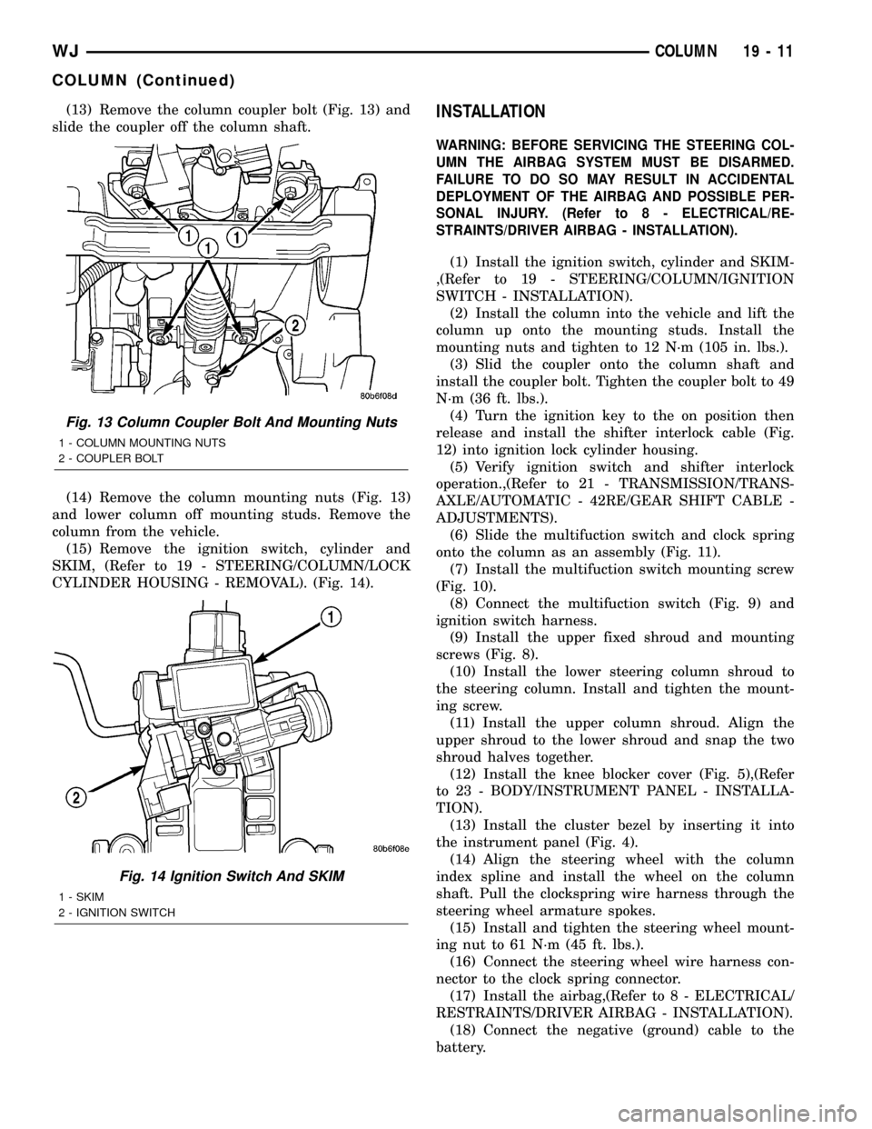
(13) Remove the column coupler bolt (Fig. 13) and
slide the coupler off the column shaft.
(14) Remove the column mounting nuts (Fig. 13)
and lower column off mounting studs. Remove the
column from the vehicle.
(15) Remove the ignition switch, cylinder and
SKIM, (Refer to 19 - STEERING/COLUMN/LOCK
CYLINDER HOUSING - REMOVAL). (Fig. 14).INSTALLATION
WARNING: BEFORE SERVICING THE STEERING COL-
UMN THE AIRBAG SYSTEM MUST BE DISARMED.
FAILURE TO DO SO MAY RESULT IN ACCIDENTAL
DEPLOYMENT OF THE AIRBAG AND POSSIBLE PER-
SONAL INJURY. (Refer to 8 - ELECTRICAL/RE-
STRAINTS/DRIVER AIRBAG - INSTALLATION).
(1) Install the ignition switch, cylinder and SKIM-
,(Refer to 19 - STEERING/COLUMN/IGNITION
SWITCH - INSTALLATION).
(2) Install the column into the vehicle and lift the
column up onto the mounting studs. Install the
mounting nuts and tighten to 12 N´m (105 in. lbs.).
(3) Slid the coupler onto the column shaft and
install the coupler bolt. Tighten the coupler bolt to 49
N´m (36 ft. lbs.).
(4) Turn the ignition key to the on position then
release and install the shifter interlock cable (Fig.
12) into ignition lock cylinder housing.
(5) Verify ignition switch and shifter interlock
operation.,(Refer to 21 - TRANSMISSION/TRANS-
AXLE/AUTOMATIC - 42RE/GEAR SHIFT CABLE -
ADJUSTMENTS).
(6) Slide the multifuction switch and clock spring
onto the column as an assembly (Fig. 11).
(7) Install the multifuction switch mounting screw
(Fig. 10).
(8) Connect the multifuction switch (Fig. 9) and
ignition switch harness.
(9) Install the upper fixed shroud and mounting
screws (Fig. 8).
(10) Install the lower steering column shroud to
the steering column. Install and tighten the mount-
ing screw.
(11) Install the upper column shroud. Align the
upper shroud to the lower shroud and snap the two
shroud halves together.
(12) Install the knee blocker cover (Fig. 5),(Refer
to 23 - BODY/INSTRUMENT PANEL - INSTALLA-
TION).
(13) Install the cluster bezel by inserting it into
the instrument panel (Fig. 4).
(14) Align the steering wheel with the column
index spline and install the wheel on the column
shaft. Pull the clockspring wire harness through the
steering wheel armature spokes.
(15) Install and tighten the steering wheel mount-
ing nut to 61 N´m (45 ft. lbs.).
(16) Connect the steering wheel wire harness con-
nector to the clock spring connector.
(17) Install the airbag,(Refer to 8 - ELECTRICAL/
RESTRAINTS/DRIVER AIRBAG - INSTALLATION).
(18) Connect the negative (ground) cable to the
battery.
Fig. 13 Column Coupler Bolt And Mounting Nuts
1 - COLUMN MOUNTING NUTS
2 - COUPLER BOLT
Fig. 14 Ignition Switch And SKIM
1 - SKIM
2 - IGNITION SWITCH
WJCOLUMN 19 - 11
COLUMN (Continued)
Page 1766 of 2199
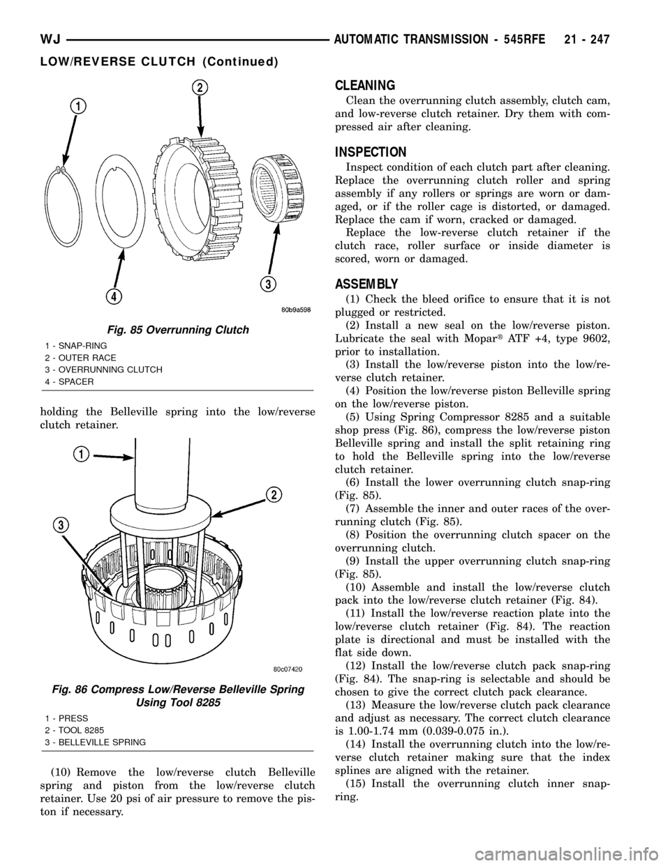
holding the Belleville spring into the low/reverse
clutch retainer.
(10) Remove the low/reverse clutch Belleville
spring and piston from the low/reverse clutch
retainer. Use 20 psi of air pressure to remove the pis-
ton if necessary.
CLEANING
Clean the overrunning clutch assembly, clutch cam,
and low-reverse clutch retainer. Dry them with com-
pressed air after cleaning.
INSPECTION
Inspect condition of each clutch part after cleaning.
Replace the overrunning clutch roller and spring
assembly if any rollers or springs are worn or dam-
aged, or if the roller cage is distorted, or damaged.
Replace the cam if worn, cracked or damaged.
Replace the low-reverse clutch retainer if the
clutch race, roller surface or inside diameter is
scored, worn or damaged.
ASSEMBLY
(1) Check the bleed orifice to ensure that it is not
plugged or restricted.
(2) Install a new seal on the low/reverse piston.
Lubricate the seal with MopartATF +4, type 9602,
prior to installation.
(3) Install the low/reverse piston into the low/re-
verse clutch retainer.
(4) Position the low/reverse piston Belleville spring
on the low/reverse piston.
(5) Using Spring Compressor 8285 and a suitable
shop press (Fig. 86), compress the low/reverse piston
Belleville spring and install the split retaining ring
to hold the Belleville spring into the low/reverse
clutch retainer.
(6) Install the lower overrunning clutch snap-ring
(Fig. 85).
(7) Assemble the inner and outer races of the over-
running clutch (Fig. 85).
(8) Position the overrunning clutch spacer on the
overrunning clutch.
(9) Install the upper overrunning clutch snap-ring
(Fig. 85).
(10) Assemble and install the low/reverse clutch
pack into the low/reverse clutch retainer (Fig. 84).
(11) Install the low/reverse reaction plate into the
low/reverse clutch retainer (Fig. 84). The reaction
plate is directional and must be installed with the
flat side down.
(12) Install the low/reverse clutch pack snap-ring
(Fig. 84). The snap-ring is selectable and should be
chosen to give the correct clutch pack clearance.
(13) Measure the low/reverse clutch pack clearance
and adjust as necessary. The correct clutch clearance
is 1.00-1.74 mm (0.039-0.075 in.).
(14) Install the overrunning clutch into the low/re-
verse clutch retainer making sure that the index
splines are aligned with the retainer.
(15) Install the overrunning clutch inner snap-
ring.
Fig. 85 Overrunning Clutch
1 - SNAP-RING
2 - OUTER RACE
3 - OVERRUNNING CLUTCH
4 - SPACER
Fig. 86 Compress Low/Reverse Belleville Spring
Using Tool 8285
1 - PRESS
2 - TOOL 8285
3 - BELLEVILLE SPRING
WJAUTOMATIC TRANSMISSION - 545RFE 21 - 247
LOW/REVERSE CLUTCH (Continued)
Page 1991 of 2199
SEALER LOCATIONS
SPECIFICATIONS
SEALER LOCATIONS
INDEX
DESCRIPTION FIGURE
APPLICATION METHODS 6
COWL PLENUM AND DASH PANEL 7
DASH, COWL AND PLENUM 8
INNER FENDER AND COWL 9
LOWER PLENUM AND BAFFLE 10
A-PILLAR 11
COWL SIDE ATTACHMENT 12
BODYSIDE ATTACHMENT 13
BODYSIDE INNER AND OUTER TO COWL 14
FENDER ATTACHMENT 15
DOOR HINGE BOLT HOLES 16
A-PILLAR AND B-PILLAR HINGE AREA 17
B-PILLAR AND SILL 18
SILL AND B-PILLAR 19
BODYSIDE APERTURE AND REAR WHEELHOUSE 20
FUEL FILLER GUSSET 21
OUTER WHEELHOUSE FLANGE 22
LIFTGATE OPENING 23
INNER WHEELHOUSE FLANGE TO BODYSIDE APERTURE 24
WHEELHOUSE LOWER 25
REAR INNER CROSSMEMBER 26
ROOF TO BODY SIDE APERTURE 27
23 - 118 BODY STRUCTUREWJ
Page 2010 of 2199
STUCTURAL ADHESIVE
LOCATIONS
SPECIFICATIONS - STRUCTURAL ADHESIVE
LOCATIONS
INDEX
DESCRIPTION FIGURE
COWL PLENUM 28
DASH PANEL AND FRONT FLOOR PAN 29
PLENUM AND WINDSHIELD WIPER MOUNTING 30
FRONT FLOOR PAN AND SILLS 31
FRONT AND CENTER FLOOR PAN 32
FRONT PAN AND INNER BODY SIDE APERTURE 33
REAR SEAT CROSSMEMBER 34
REAR INNER WHEELHOUSE 35
FLOOR PAN AND SILL ASSEMBLY 36
FLOOR PAN 37
REAR INNER WHEELHOUSE AND REAR FLOOR PAN 38
RIGHT INNER BODYSIDE APERTURE 39
BODY SIDE INNER PANEL AND WHEELHOUSE 40
BODY SIDE OUTER PANEL AND REAR WHEELHOUSE OUTER PANEL 41
D-PILLAR AND FUEL FILLER GUSSETS 42
LIFTGATE 43
TAILLAMP MOUNTING PANEL 44
TAILLAMP 45
REAR INNER CROSSMEMBER 46
ROOF BOWS 47
REAR LOWER HEADER 48
WJBODY STRUCTURE 23 - 137
Page 2026 of 2199
WELD LOCATIONS
SPECIFICATIONS
WELD LOCATIONS
INDEX
DESCRIPTION FIGURE
RADIATOR SUPPORT BRACKETS 49
FRONT SUSPENSION SUPPORT REINFORCEMENT 50
FRONT LOWER CROSSMEMBER TO COWL SIDE PANEL 51
FRONT SILL TO LOWER CROSSMEMBER 52
FRONT FENDER MOUNTING BRACKET AND REINFORCEMENT 53
FRONT SUSPENSION SUPPORT TO SILLS AND COWL SIDE PANEL 54
LEFT INSTRUMENT PANEL BRACKET TO COWL SIDE PANEL 55
COWL SIDE UPPER REINFORCEMENT TO COWL SIDE AND FRONT SUSPENSION
SUPPORT56
COWL SIDE PANEL TO DASH PANEL AND INNER BODYSIDE PANEL AND SILL 57
PLENUM ASSEMBLY TO COWL SIDE PANEL 58
FRONT LOWER CROSSMEMBER 59
FRONT SUSPENSION SUPPORT TO DASH 60
WIPER MOUNTING BRACKETS TO PLENUM ASSEMBLY 61
COWL TOP AND PLENUM ASSEMBLY 62
LOWER PLENUM REINFORCEMENT TO LOWER PLENUM PANEL 63
DASH PANEL TO LOWER PLENUM PANEL 64
PLENUM ASSEMBLY TO COWL 65
COWL PANEL TO BODYSIDE SILL 66
COWL PANEL TO FRONT FLOOR PAN 67
FRONT SILLS TO DASH AND FRONT FLOOR PAN 68
COWL SIDE PANEL DASH INNER BODYSIDE AND OUTER BODYSIDE PANELS 69
UPPER FRONT INNER PILLAR TO ROOF AND COWL 70
DOOR OPENINGS 71
B-PILLAR REINFORCEMENT TO INNER BODYSIDE APERTURE 72
REAR QUARTER WINDOW TO BODYSIDE APERTURE INNER AND OUTER 73
LOWER REAR QUARTER TO BODYSIDE APERTURE INNER AND OUTER 74
INNER TRACK BAR, LOWER CONTROL ARM AND TRANSMISSION CROSSMEMBER
BRACKETS TO FRONT SILLS75
TRANSMISSION CROSSMEMBER BRACKET AND REINFORCEMENT TO FRONT
SILLS76
UPPER SILLS AND UPPER CONTROL ARM REINFORCEMENT AND BRACKETS TO
FRONT SILLS77
REINFORCEMENT TO FRONT OUTER SILLS 78
FRONT INNER SILL TO FRONT OUTER SILL 79
OUTER TRACK BAR BRACKET TO FRONT OUTER SILL 80
WJBODY STRUCTURE 23 - 153