2002 JEEP GRAND CHEROKEE Index
[x] Cancel search: IndexPage 654 of 2199

WIRING
TABLE OF CONTENTS
page page
WIRING DIAGRAM INFORMATION....... 8W-01-1
COMPONENT INDEX.................. 8W-02-1
POWER DISTRIBUTION............... 8W-10-1
JUNCTION BLOCK.................... 8W-12-1
GROUND DISTRIBUTION.............. 8W-15-1
BUS COMMUNICATIONS.............. 8W-18-1
CHARGING SYSTEM.................. 8W-20-1
STARTING SYSTEM.................. 8W-21-1
FUEL/IGNITION SYSTEM.............. 8W-30-1
TRANSMISSION CONTROL SYSTEM..... 8W-31-1
VEHICLE SPEED CONTROL............ 8W-33-1
ANTILOCK BRAKES................... 8W-35-1
VEHICLE THEFT SECURITY SYSTEM..... 8W-39-1
INSTRUMENT CLUSTER............... 8W-40-1
HORN/CIGAR LIGHTER/POWER OUTLET . . 8W-41-1
AIR CONDITIONING-HEATER........... 8W-42-1
AIRBAG SYSTEM.................... 8W-43-1
INTERIOR LIGHTING.................. 8W-44-1
BODY CONTROL MODULE............. 8W-45-1AUDIO SYSTEM..................... 8W-47-1
REAR WINDOW DEFOGGER............ 8W-48-1
OVERHEAD CONSOLE................. 8W-49-1
FRONT LIGHTING.................... 8W-50-1
REAR LIGHTING..................... 8W-51-1
TURN SIGNALS...................... 8W-52-1
WIPERS............................ 8W-53-1
TRAILER TOW....................... 8W-54-1
POWER WINDOWS................... 8W-60-1
POWER DOOR LOCKS................ 8W-61-1
POWER MIRRORS................... 8W-62-1
POWER SEATS...................... 8W-63-1
POWER SUNROOF................... 8W-64-1
SPLICE INFORMATION................ 8W-70-1
CONNECTOR PIN-OUT................ 8W-80-1
CONNECTOR/GROUND/SPLICE
LOCATION........................ 8W-91-1
POWER DISTRIBUTION............... 8W-97-1 WJWIRING 8W - 1
Page 672 of 2199

8W-02 COMPONENT INDEX
Component Page
A/C Compressor Clutch................. 8W-42
A/C Pressure Transducer................ 8W-42
Accelerator Pedal Position Sensor......... 8W-30
Accessory Delay Relay.................. 8W-64
Adjustable Pedals..................... 8W-30
Airbags............................. 8W-43
Ambient Temperature Sensor............ 8W-45
Antennas............................ 8W-47
Ash Receiver Lamp.................... 8W-44
Auto Shut Down Relay................. 8W-30
Automatic Day/Night Mirror............. 8W-49
Automatic Headlamp Light Sensor/VTSS
LED.............................. 8W-39
Automatic Zone Control Module.......... 8W-42
Back-Up Lamp Relay................... 8W-51
Battery Temperature Sensor............. 8W-30
Battery............................. 8W-20
Blend Door Motor/Actuator.............. 8W-42
Blower Motor......................... 8W-42
Body Control Module................... 8W-45
Boost Pressure Sensor.................. 8W-30
Brake Lamp Switch.................... 8W-33
Camshaft Position Sensor............... 8W-30
Capacitors........................... 8W-30
Cargo Lamp.......................... 8W-44
Center High Mounted Stop Lamp......... 8W-51
Cigar Lighter......................... 8W-41
Circuit Breakers...................... 8W-12
Clockspring.................. 8W-33, 41, 43, 47
Coil On Plugs......................... 8W-30
Coil Rail............................. 8W-30
Combination Flasher................... 8W-52
Compact Disc Changer.................. 8W-47
Controller Antilock Brake............... 8W-35
Coolant Level Sensor................... 8W-45
Courtesy Lamps....................... 8W-44
Crankcase Heater..................... 8W-30
Crankshaft Position Sensor.............. 8W-30
Cylinder Lock Switches................. 8W-61
Data Link Connector................... 8W-18
Diagnostic Junction Port................ 8W-18
EGR Solenoid......................... 8W-30
Electric Brake........................ 8W-54
Electronic Speed Control Servo........... 8W-33
Engine Control Module................. 8W-30
Engine Coolant Temperature Sensor...... 8W-30
Engine Oil Pressure Sensor.............. 8W-30
Engine Starter Motor................... 8W-21
EVAP/Purge Solenoid................... 8W-30
Fog Lamps........................ 8W-50, 51
Fuel Injectors......................... 8W-30
Fuel Pressure Sensor................... 8W-30Component Page
Fuel Pressure Solenoid................. 8W-30
Fuel Pump........................... 8W-30
Fuel Tank Module..................... 8W-30
Fuses............................ 8W-10, 12
Fusible Link....................... 8W-10, 20
Grounds............................. 8W-15
Generator......................... 8W-20, 30
Glove Box Lamp...................... 8W-44
Glow Plugs........................... 8W-30
Headlamp Leveling Motor............... 8W-50
Heated Seats......................... 8W-63
High Beam Headlamps................. 8W-50
Hood Ajar Switch...................... 8W-39
Horns............................... 8W-41
Hydraulic Cooling Module............ 8W-30, 42
Idle Air Control Motor.................. 8W-30
Ignition Switch....................... 8W-10
Impact Sensors....................... 8W-43
Input Speed Sensor.................... 8W-31
Instrument Cluster.................... 8W-40
Intake Air Temperature Sensor........... 8W-30
Intake Port Swirl Actuator.............. 8W-30
Intrusion Transceiver Module............ 8W-49
Junction Block........................ 8W-12
Knock Sensor......................... 8W-30
Lamp Assemblies................... 8W-51, 52
Leak Detection Pump.................. 8W-30
License Lamps........................ 8W-51
Liftgate............................. 8W-61
Line Pressure Sensor................... 8W-31
Low Beam Headlamps.................. 8W-50
Low Beam Relay...................... 8W-50
Low Beam/Daytime Running Lamp Relay . . . 8W-50
Lumbar Motor........................ 8W-63
Lumbar Switch....................... 8W-63
Manifold Absolute Pressure Sensor........ 8W-30
Manual Temperature Control............. 8W-42
Mass Air Flow Sensor.................. 8W-30
Memory Set Switch................. 8W-62, 63
Mode Door Motor/Actuator............... 8W-42
Multi-Function Switch............... 8W-50, 53
Output Speed Sensor................... 8W-31
Overhead Map/Courtesy Lamp........... 8W-44
Oxygen Sensors....................... 8W-30
Park Brake Switch..................... 8W-40
Park Lamp........................... 8W-50
Park/Neutral Position Switch............ 8W-31
Park/Turn Signal Lamps................ 8W-50
Power Amplifier....................... 8W-47
Power Connector...................... 8W-41
Power Distribution Center............... 8W-10
Power Mirrors........................ 8W-62
WJ8W-02 COMPONENT INDEX 8W - 02 - 1
Page 673 of 2199

Component Page
Power Outlet......................... 8W-41
Power Seats.......................... 8W-63
Power Windows....................... 8W-60
Powertrain Control Module.............. 8W-30
Radio............................... 8W-47
Rain Sensor.......................... 8W-49
Recirculation Door Motor/Actuator........ 8W-42
Red Brake Warning Indicator Switch....... 8W-35
Remote Keyless Module................. 8W-39
Remote Radio Switches................. 8W-47
Splices.............................. 8W-10
Seat Belt Switch...................... 8W-43
Seat Module.......................... 8W-63
Sentry Key Immobilizer Module.......... 8W-39
Shifter Assembly...................... 8W-31
Side Impact Sensors................... 8W-43
Side Marker Lamps.................... 8W-50
Side Repeater Lamps................... 8W-52
Siren............................... 8W-49
Speakers............................ 8W-47Component Page
Speed Control Switches................. 8W-33
Sunroof............................. 8W-64
Temperature Valve Actuator............. 8W-42
Throttle Position Sensor................ 8W-30
Trailer Tow.......................... 8W-54
Transfer Case Position Sensor............ 8W-31
Transmission......................... 8W-31
Turn Signal Lamps.................... 8W-52
Underhood Lamp...................... 8W-44
Vehicle Information Center.............. 8W-49
Viscous/Cabin Heater................... 8W-30
Visor/Vanity Lamps.................... 8W-44
Washer Fluid Level Switch.............. 8W-53
Wastegate Solenoid.................... 8W-30
Water In Fuel Sensor................... 8W-30
Wheel Speed Sensors................... 8W-35
Window Defogger...................... 8W-48
Wiper High/Low Relay.................. 8W-53
Wiper Motor.......................... 8W-53
Washer Pump......................... 8W-5
8W - 02 - 2 8W-02 COMPONENT INDEXWJ
Page 1176 of 2199

8W-91 CONNECTOR/GROUND/SPLICE LOCATION
TABLE OF CONTENTS
page
CONNECTOR/GROUND/SPLICE LOCATION
DESCRIPTION..........................1
CONNECTOR/GROUND/SPLICE
LOCATION
DESCRIPTION
This section provides illustrations identifying con-
nector, ground, and splice locations in the vehicle.Connector, ground, and splice indexes are provided.
Use the wiring diagrams in each section for connec-
tor, ground, and splice identification. Refer to the
appropriate index for the proper figure number. For
items that are not shown in this section N/S is placed
in the Fig. column.
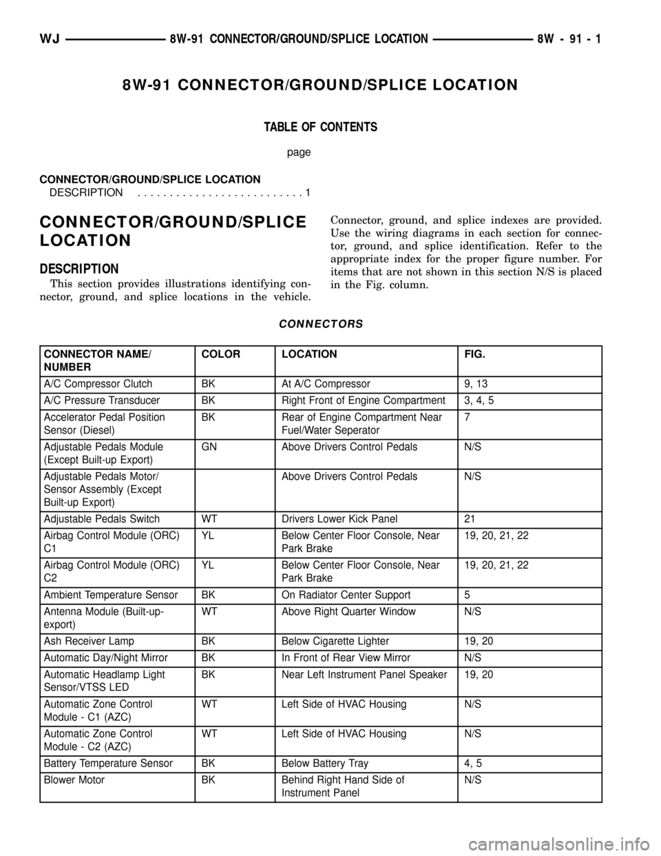
CONNECTORS
CONNECTOR NAME/
NUMBERCOLOR LOCATION FIG.
A/C Compressor Clutch BK At A/C Compressor 9, 13
A/C Pressure Transducer BK Right Front of Engine Compartment 3, 4, 5
Accelerator Pedal Position
Sensor (Diesel)BK Rear of Engine Compartment Near
Fuel/Water Seperator7
Adjustable Pedals Module
(Except Built-up Export)GN Above Drivers Control Pedals N/S
Adjustable Pedals Motor/
Sensor Assembly (Except
Built-up Export)Above Drivers Control Pedals N/S
Adjustable Pedals Switch WT Drivers Lower Kick Panel 21
Airbag Control Module (ORC)
C1YL Below Center Floor Console, Near
Park Brake19, 20, 21, 22
Airbag Control Module (ORC)
C2YL Below Center Floor Console, Near
Park Brake19, 20, 21, 22
Ambient Temperature Sensor BK On Radiator Center Support 5
Antenna Module (Built-up-
export)WT Above Right Quarter Window N/S
Ash Receiver Lamp BK Below Cigarette Lighter 19, 20
Automatic Day/Night Mirror BK In Front of Rear View Mirror N/S
Automatic Headlamp Light
Sensor/VTSS LEDBK Near Left Instrument Panel Speaker 19, 20
Automatic Zone Control
Module - C1 (AZC)WT Left Side of HVAC Housing N/S
Automatic Zone Control
Module - C2 (AZC)WT Left Side of HVAC Housing N/S
Battery Temperature Sensor BK Below Battery Tray 4, 5
Blower Motor BK Behind Right Hand Side of
Instrument PanelN/S
WJ8W-91 CONNECTOR/GROUND/SPLICE LOCATION 8W - 91 - 1
Page 1236 of 2199

CAUTION: Do not remove the wiring and terminals
from the terminal cavities of the faulty PDC relay
cassette at this time. Refer to the Assembly proce-
dure that follows for the proper procedures for
transferring the wiring and terminals to the replace-
ment PDC relay cassette.
ASSEMBLY
POWER DISTRIBUTION CENTER ASSEMBLY
PDC B(+) TERMINAL MODULE INSTALLATION
(1) From the bottom of the PDC housing, align and
insert the B(+) terminal module into the PDC.
(2) From the bottom of the PDC housing, align and
insert the two studs of the PDC B(+) terminal mod-
ule through the bus bar in the PDC.
(3) From the bottom of the PDC housing, press the
B(+) terminal module gently and evenly into the PDC
until both of the latches are fully engaged.
(4) Install the PDC housing lower cover.
RELAY WEDGE INSTALLATION
(1) From the top of the PDC housing, align and
insert the PDC relay wedge latch arms into the cor-
rect cavities in the relay cassette.
(2) Gently and evenly press the PDC relay wedge
down into the relay cassette until both of the latches
are fully engaged.
(3) Install each of the removed relays into the
proper cavities of the PDC relay wedge.
(4) Install the PDC housing lower cover.
RELAY CASSETTE INSTALLATION
(1) Move the faulty PDC relay cassette with its
wiring away from the bottom of the PDC housing far
enough to allow the replacement relay cassette to be
installed into the PDC.
(2) Using the faulty relay cassette as a guide, be
certain that the replacement relay cassette is cor-
rectly oriented before installing it into the PDC hous-
ing.
(3) From the bottom of the PDC housing, align and
insert the replacement relay cassette into the PDC.
Press the relay cassette up into the PDC until both
of the latches are fully engaged.
CAUTION: Proper care must be taken to be certain
that the wiring and terminals from the faulty PDC
relay cassette are installed in the correct terminal
cavities of the replacement relay cassette. To pre-
vent mistakes it is recommended that the wiring
and terminals be removed from the faulty relay cas-
sette one cavity at a time, repaired or spliced as
necessary, then installed securely into the correctcavity of the replacement relay cassette. If you are
not absolutely certain into which cavity a terminal
should be installed, refer to Power Distribution in
the index of this service manual for the location of
complete circuit diagrams covering the PDC.
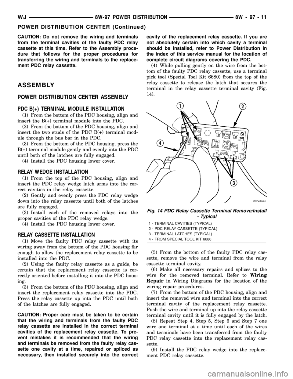
(4) While pulling gently on the wire from the bot-
tom of the faulty PDC relay cassette, use a terminal
pick tool (Special Tool Kit 6680) from the top of the
relay cassette to release the latch that secures the
terminal in the relay cassette terminal cavity (Fig.
14).
(5) From the bottom of the faulty PDC relay cas-
sette, remove the wire and terminal from the relay
cassette terminal cavity.
(6) Make all necessary repairs and splices to the
wire for the removed terminal. Refer toWiring
Repairin Wiring Diagrams for the location of the
wiring repair procedures.
(7) From the bottom of the PDC housing, align and
insert the removed wire and terminal into the correct
terminal cavity of the replacement relay cassette.
Push the wire and terminal up into the relay cassette
terminal cavity until it is fully engaged by the latch.
(8) Repeat Step 4, Step 5, Step 6 and Step 7 one
wire and terminal at a time until each of the wires
and terminals have been transferred from the faulty
PDC relay cassette into the replacement relay cas-
sette.
(9) Install the PDC relay wedge into the replace-
ment PDC relay cassette.
Fig. 14 PDC Relay Cassette Terminal Remove/Install
- Typical
1 - TERMINAL CAVITIES (TYPICAL)
2 - PDC RELAY CASSETTE (TYPICAL)
3 - TERMINAL LATCHES (TYPICAL)
4 - FROM SPECIAL TOOL KIT 6680
WJ8W-97 POWER DISTRIBUTION 8W - 97 - 11
POWER DISTRIBUTION CENTER (Continued)
Page 1240 of 2199

ground at all times. If not OK, repair the open
ground circuit to ground as required.
REMOVAL
(1) Disconnect and isolate the battery negative
cable.
(2) Remove the steering column opening cover
from the instrument panel. Refer toSteering Col-
umn Opening Coverin Body for the procedure.
(3) The power outlet / cigar lighter relay is located
on the left side of the combination flasher in the
junction block.
(4) Remove the power outlet / cigar lighter relay
from the junction block.
INSTALLATION
(1) Position the power outlet / cigar lighter relay in
the proper receptacle in the junction block.
(2) Align the power outlet / cigar lighter relay ter-
minals with the terminal cavities in the junction
block receptacle.
(3) Push in firmly on the power outlet / cigar
lighter relay until the terminals are fully seated in
the terminal cavities in the junction block receptacle.
(4) Install the steering column opening cover onto
the instrument panel. Refer toSteering Column
Opening Coverin Body for the procedure.
(5) Reconnect the battery negative cable.
IOD WIRE HARNESS
CONNECTOR
DESCRIPTION
All vehicles are equipped with an Ignition-Off
Draw (IOD) connector that is located in a molded
connector receptacle on the lower rear surface of the
Junction Block (JB) housing (Fig. 17). The JB is con-
cealed above the molded plastic instrument panel
fuse cover. Integral latches molded into the fuse
cover secure it the JB, the Body Control Module
(BCM) and the 16-way data link connector tab of the
instrument panel steering column support bracket.
The fuse cover can be pulled downward to disengage
the latches and provide service access to all of the
fuses, relays and wire harness connectors of the JB.
Refer toInstrument Panel Fuse Coverin the
index of this service manual for the location of addi-
tional service information covering the fuse cover.
OPERATION
The term ignition-off draw identifies a normal con-
dition where power is being drained from the battery
with the ignition switch in the Off position. The IOD
connector feeds the memory and sleep mode func-
tions for some of the electronic modules in the vehicleas well as various other accessories that require bat-
tery current when the ignition switch is in the Off
position, including the clock.
The IOD connector can be used by the vehicle
owner as a convenient means of reducing battery
depletion when a vehicle is to be stored for periods
not to exceed about twenty days (short-term storage).
Simply disconnect the IOD connector from the JB
receptacle. However, it must be remembered that dis-
connecting the IOD connector will not eliminate IOD,
but only reduce this normal condition. When a vehi-
cle will not be used for more than twenty days, but
less than thirty days, remove the IOD fuse from the
Power Distribution Center (PDC). If a vehicle will be
stored for more than about thirty days, the battery
negative cable should be disconnected to eliminate
normal IOD; and, the battery should be tested and
recharged at regular intervals during the vehicle
storage period to prevent the battery from becoming
discharged or damaged. Refer toIgnition-Off Draw
Fig. 17 Ignition-Off Draw Connector
1 - SNAP CLIPS
2 - SCREW
3 - CONNECTOR
4 - LEFT BODY WIRE HARNESS
5 - IOD CONNECTOR
6 - FUSED B+ CONNECTOR
7 - RIGHT BODY WIRE HARNESS
8 - SCREW
9 - CONNECTOR
10 - JUNCTION BLOCK
WJ8W-97 POWER DISTRIBUTION 8W - 97 - 15
POWER OUTLET RELAY (Continued)
Page 1241 of 2199

FuseandBatteryin the index in this service man-
ual for the location of additional service information
covering the ignition-off draw fuse and the battery.
FUSE COVER
REMOVAL
(1) Disconnect and isolate the battery negative
cable.
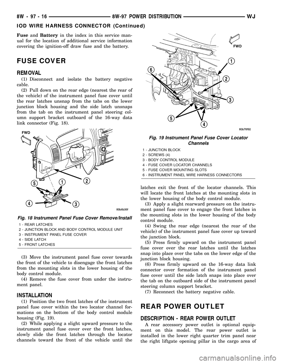
(2) Pull down on the rear edge (nearest the rear of
the vehicle) of the instrument panel fuse cover until
the rear latches unsnap from the tabs on the lower
junction block housing and the side latch unsnaps
from the tab on the instrument panel steering col-
umn support bracket outboard of the 16-way data
link connector (Fig. 18).
(3) Move the instrument panel fuse cover towards
the front of the vehicle to disengage the front latches
from the mounting slots in the lower housing of the
body control module.
(4) Remove the fuse cover from under the instru-
ment panel.
INSTALLATION
(1) Position the two front latches of the instrument
panel fuse cover within the two locator channel for-
mations on the bottom of the body control module
housing (Fig. 19).
(2) While applying a slight upward pressure to the
instrument panel fuse cover over the front latches,
slowly slide the front latches through the locator
channels toward the front of the vehicle until thelatches exit the front of the locator channels. This
will locate the front latches at the mounting slots in
the lower housing of the body control module.
(3) Apply a slight rearward pressure on the instru-
ment panel fuse cover to engage the front latches in
the mounting slots in the lower housing of the body
control module.
(4) Swing the rear edge (nearest the rear of the
vehicle) of the instrument panel fuse cover up toward
the junction block.
(5) Press firmly upward on the instrument panel
fuse cover over the rear latches until the latches
snap into place over the tabs on the lower edge of the
junction block housing.
(6) Press firmly upward on the 16-way data link
connector cover formation of the instrument panel
fuse cover until the side latch snaps into place over
the tab on the outboard side of the instrument panel
steering column support bracket.
(7) Reconnect the battery negative cable.
REAR POWER OUTLET
DESCRIPTION - REAR POWER OUTLET
A rear accessory power outlet is optional equip-
ment on this model. The rear power outlet is
installed in the lower right quarter trim panel near
the right liftgate opening pillar in the cargo area of
Fig. 18 Instrument Panel Fuse Cover Remove/Install
1 - REAR LATCHES
2 - JUNCTION BLOCK AND BODY CONTROL MODULE UNIT
3 - INSTRUMENT PANEL FUSE COVER
4 - SIDE LATCH
5 - FRONT LATCHES
Fig. 19 Instrument Panel Fuse Cover Locator
Channels
1 - JUNCTION BLOCK
2 - SCREWS (4)
3 - BODY CONTROL MODULE
4 - FUSE COVER LOCATOR CHANNELS
5 - FUSE COVER MOUNTING SLOTS
6 - INSTRUMENT PANEL WIRE HARNESS CONNECTORS
8W - 97 - 16 8W-97 POWER DISTRIBUTIONWJ
IOD WIRE HARNESS CONNECTOR (Continued)
Page 1386 of 2199

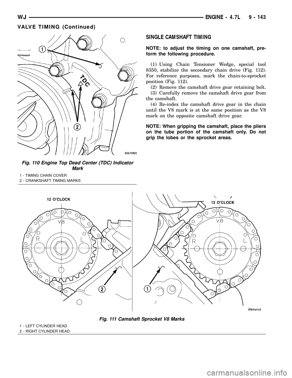
SINGLE CAMSHAFT TIMING
NOTE: to adjust the timing on one camshaft, pre-
form the following procedure.
(1) Using Chain Tensioner Wedge, special tool
8350, stabilize the secondary chain drive (Fig. 112).
For reference purposes, mark the chain-to-sprocket
position (Fig. 112).
(2) Remove the camshaft drive gear retaining bolt.
(3) Carefully remove the camshaft drive gear from
the camshaft.
(4) Re-index the camshaft drive gear in the chain
until the V8 mark is at the same position as the V8
mark on the opposite camshaft drive gear.
NOTE: When gripping the camshaft, place the pliers
on the tube portion of the camshaft only. Do not
grip the lobes or the sprocket areas.
Fig. 110 Engine Top Dead Center (TDC) Indicator
Mark
1 - TIMING CHAIN COVER
2 - CRANKSHAFT TIMING MARKS
Fig. 111 Camshaft Sprocket V8 Marks
1 - LEFT CYLINDER HEAD
2 - RIGHT CYLINDER HEAD
WJENGINE - 4.7L 9 - 143
VALVE TIMING (Continued)