2002 JEEP GRAND CHEROKEE power seats
[x] Cancel search: power seatsPage 672 of 2199

8W-02 COMPONENT INDEX
Component Page
A/C Compressor Clutch................. 8W-42
A/C Pressure Transducer................ 8W-42
Accelerator Pedal Position Sensor......... 8W-30
Accessory Delay Relay.................. 8W-64
Adjustable Pedals..................... 8W-30
Airbags............................. 8W-43
Ambient Temperature Sensor............ 8W-45
Antennas............................ 8W-47
Ash Receiver Lamp.................... 8W-44
Auto Shut Down Relay................. 8W-30
Automatic Day/Night Mirror............. 8W-49
Automatic Headlamp Light Sensor/VTSS
LED.............................. 8W-39
Automatic Zone Control Module.......... 8W-42
Back-Up Lamp Relay................... 8W-51
Battery Temperature Sensor............. 8W-30
Battery............................. 8W-20
Blend Door Motor/Actuator.............. 8W-42
Blower Motor......................... 8W-42
Body Control Module................... 8W-45
Boost Pressure Sensor.................. 8W-30
Brake Lamp Switch.................... 8W-33
Camshaft Position Sensor............... 8W-30
Capacitors........................... 8W-30
Cargo Lamp.......................... 8W-44
Center High Mounted Stop Lamp......... 8W-51
Cigar Lighter......................... 8W-41
Circuit Breakers...................... 8W-12
Clockspring.................. 8W-33, 41, 43, 47
Coil On Plugs......................... 8W-30
Coil Rail............................. 8W-30
Combination Flasher................... 8W-52
Compact Disc Changer.................. 8W-47
Controller Antilock Brake............... 8W-35
Coolant Level Sensor................... 8W-45
Courtesy Lamps....................... 8W-44
Crankcase Heater..................... 8W-30
Crankshaft Position Sensor.............. 8W-30
Cylinder Lock Switches................. 8W-61
Data Link Connector................... 8W-18
Diagnostic Junction Port................ 8W-18
EGR Solenoid......................... 8W-30
Electric Brake........................ 8W-54
Electronic Speed Control Servo........... 8W-33
Engine Control Module................. 8W-30
Engine Coolant Temperature Sensor...... 8W-30
Engine Oil Pressure Sensor.............. 8W-30
Engine Starter Motor................... 8W-21
EVAP/Purge Solenoid................... 8W-30
Fog Lamps........................ 8W-50, 51
Fuel Injectors......................... 8W-30
Fuel Pressure Sensor................... 8W-30Component Page
Fuel Pressure Solenoid................. 8W-30
Fuel Pump........................... 8W-30
Fuel Tank Module..................... 8W-30
Fuses............................ 8W-10, 12
Fusible Link....................... 8W-10, 20
Grounds............................. 8W-15
Generator......................... 8W-20, 30
Glove Box Lamp...................... 8W-44
Glow Plugs........................... 8W-30
Headlamp Leveling Motor............... 8W-50
Heated Seats......................... 8W-63
High Beam Headlamps................. 8W-50
Hood Ajar Switch...................... 8W-39
Horns............................... 8W-41
Hydraulic Cooling Module............ 8W-30, 42
Idle Air Control Motor.................. 8W-30
Ignition Switch....................... 8W-10
Impact Sensors....................... 8W-43
Input Speed Sensor.................... 8W-31
Instrument Cluster.................... 8W-40
Intake Air Temperature Sensor........... 8W-30
Intake Port Swirl Actuator.............. 8W-30
Intrusion Transceiver Module............ 8W-49
Junction Block........................ 8W-12
Knock Sensor......................... 8W-30
Lamp Assemblies................... 8W-51, 52
Leak Detection Pump.................. 8W-30
License Lamps........................ 8W-51
Liftgate............................. 8W-61
Line Pressure Sensor................... 8W-31
Low Beam Headlamps.................. 8W-50
Low Beam Relay...................... 8W-50
Low Beam/Daytime Running Lamp Relay . . . 8W-50
Lumbar Motor........................ 8W-63
Lumbar Switch....................... 8W-63
Manifold Absolute Pressure Sensor........ 8W-30
Manual Temperature Control............. 8W-42
Mass Air Flow Sensor.................. 8W-30
Memory Set Switch................. 8W-62, 63
Mode Door Motor/Actuator............... 8W-42
Multi-Function Switch............... 8W-50, 53
Output Speed Sensor................... 8W-31
Overhead Map/Courtesy Lamp........... 8W-44
Oxygen Sensors....................... 8W-30
Park Brake Switch..................... 8W-40
Park Lamp........................... 8W-50
Park/Neutral Position Switch............ 8W-31
Park/Turn Signal Lamps................ 8W-50
Power Amplifier....................... 8W-47
Power Connector...................... 8W-41
Power Distribution Center............... 8W-10
Power Mirrors........................ 8W-62
WJ8W-02 COMPONENT INDEX 8W - 02 - 1
Page 673 of 2199

Component Page
Power Outlet......................... 8W-41
Power Seats.......................... 8W-63
Power Windows....................... 8W-60
Powertrain Control Module.............. 8W-30
Radio............................... 8W-47
Rain Sensor.......................... 8W-49
Recirculation Door Motor/Actuator........ 8W-42
Red Brake Warning Indicator Switch....... 8W-35
Remote Keyless Module................. 8W-39
Remote Radio Switches................. 8W-47
Splices.............................. 8W-10
Seat Belt Switch...................... 8W-43
Seat Module.......................... 8W-63
Sentry Key Immobilizer Module.......... 8W-39
Shifter Assembly...................... 8W-31
Side Impact Sensors................... 8W-43
Side Marker Lamps.................... 8W-50
Side Repeater Lamps................... 8W-52
Siren............................... 8W-49
Speakers............................ 8W-47Component Page
Speed Control Switches................. 8W-33
Sunroof............................. 8W-64
Temperature Valve Actuator............. 8W-42
Throttle Position Sensor................ 8W-30
Trailer Tow.......................... 8W-54
Transfer Case Position Sensor............ 8W-31
Transmission......................... 8W-31
Turn Signal Lamps.................... 8W-52
Underhood Lamp...................... 8W-44
Vehicle Information Center.............. 8W-49
Viscous/Cabin Heater................... 8W-30
Visor/Vanity Lamps.................... 8W-44
Washer Fluid Level Switch.............. 8W-53
Wastegate Solenoid.................... 8W-30
Water In Fuel Sensor................... 8W-30
Wheel Speed Sensors................... 8W-35
Window Defogger...................... 8W-48
Wiper High/Low Relay.................. 8W-53
Wiper Motor.......................... 8W-53
Washer Pump......................... 8W-5
8W - 02 - 2 8W-02 COMPONENT INDEXWJ
Page 1024 of 2199
8W-63 POWER SEATS
Component Page
Body Control Module................ 8W-63-12
Circuit Breaker No. 2 (JB).... 8W-63-2, 3, 4, 10, 11
Driver Door Module.................. 8W-63-3
Driver Heated Seat Back............ 8W-63-6, 7
Driver Heated Seat Cushion.......... 8W-63-6, 7
Driver Heated Seat Switch............ 8W-63-12
Driver Lumbar Motor............. 8W-63-10, 11
Driver Lumbar Switch............. 8W-63-10, 11
Driver Power Seat Front Riser Motor . . . 8W-63-2, 5
Driver Power Seat Front Riser
Motor Sensor..................... 8W-63-8
Driver Power Seat Horizontal Motor.... 8W-63-2, 5
Driver Power Seat Horizontal
Motor Sensor.................... 8W-63-8, 9
Driver Power Seat Rear Riser Motor . . . 8W-63-2, 5
Driver Power Seat Rear Riser
Motor Sensor..................... 8W-63-8
Driver Power Seat Recliner Motor..... 8W-63-2, 5
Driver Power Seat Recliner
Motor Sensor.................... 8W-63-8, 9Component Page
Driver Power Seat Switch............ 8W-63-2, 5
Fuse 20........................... 8W-63-12
G200............................. 8W-63-12
G300.................... 8W-63-3, 4, 5, 10, 11
G301.................. 8W-63-2, 3, 4, 5, 10, 11
Junction Block.......... 8W-63-2, 3, 4, 10, 11, 12
Memory Set Switch................... 8W-63-3
Passenger Heated Seat Back......... 8W-63-6, 7
Passenger Heated Seat Cushion....... 8W-63-6, 7
Passenger Heated Seat Switch......... 8W-63-12
Passenger Lumbar Motor.......... 8W-63-10, 11
Passenger Lumbar Switch.......... 8W-63-10, 11
Passenger Power Seat Front
Riser Motor....................... 8W-63-4
Passenger Power Seat Horizontal Motor . . . 8W-63-4
Passenger Power Seat Rear
Riser Motor....................... 8W-63-4
Passenger Power Seat Recliner Motor.... 8W-63-4
Passenger Power Seat Switch........... 8W-63-4
Seat Module.............. 8W-63-3, 5, 6, 7, 8, 9
WJ8W-63 POWER SEATS 8W - 63 - 1
Page 1098 of 2199
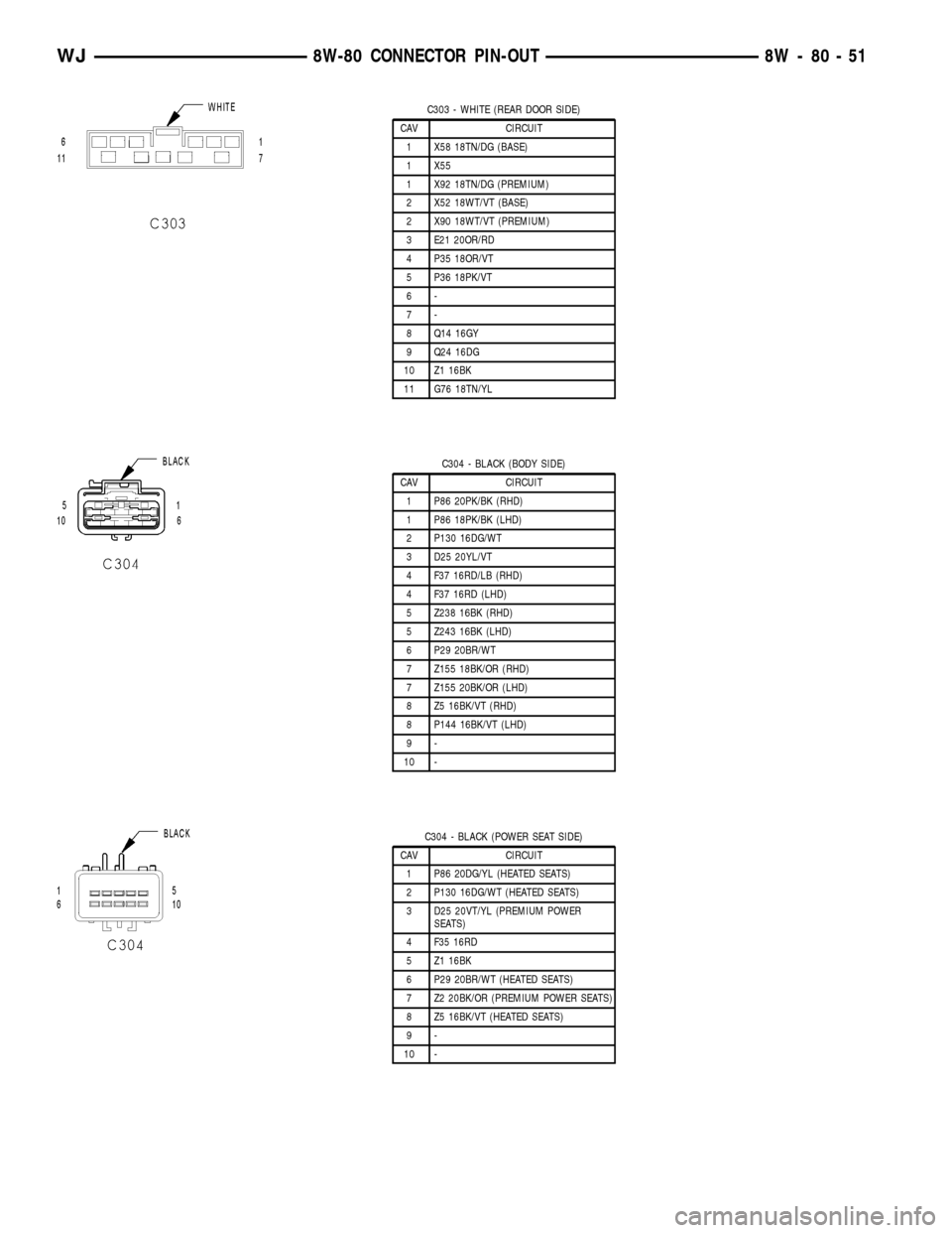
C303 - WHITE (REAR DOOR SIDE)
CAV CIRCUIT
1 X58 18TN/DG (BASE)
1 X55
1 X92 18TN/DG (PREMIUM)
2 X52 18WT/VT (BASE)
2 X90 18WT/VT (PREMIUM)
3 E21 20OR/RD
4 P35 18OR/VT
5 P36 18PK/VT
6-
7-
8 Q14 16GY
9 Q24 16DG
10 Z1 16BK
11 G76 18TN/YL
C304 - BLACK (BODY SIDE)
CAV CIRCUIT
1 P86 20PK/BK (RHD)
1 P86 18PK/BK (LHD)
2 P130 16DG/WT
3 D25 20YL/VT
4 F37 16RD/LB (RHD)
4 F37 16RD (LHD)
5 Z238 16BK (RHD)
5 Z243 16BK (LHD)
6 P29 20BR/WT
7 Z155 18BK/OR (RHD)
7 Z155 20BK/OR (LHD)
8 Z5 16BK/VT (RHD)
8 P144 16BK/VT (LHD)
9-
10 -
C304 - BLACK (POWER SEAT SIDE)
CAV CIRCUIT
1 P86 20DG/YL (HEATED SEATS)
2 P130 16DG/WT (HEATED SEATS)
3 D25 20VT/YL (PREMIUM POWER
SEATS)
4 F35 16RD
5 Z1 16BK
6 P29 20BR/WT (HEATED SEATS)
7 Z2 20BK/OR (PREMIUM POWER SEATS)
8 Z5 16BK/VT (HEATED SEATS)
9-
10 -
WJ8W-80 CONNECTOR PIN-OUT 8W - 80 - 51
Page 1099 of 2199
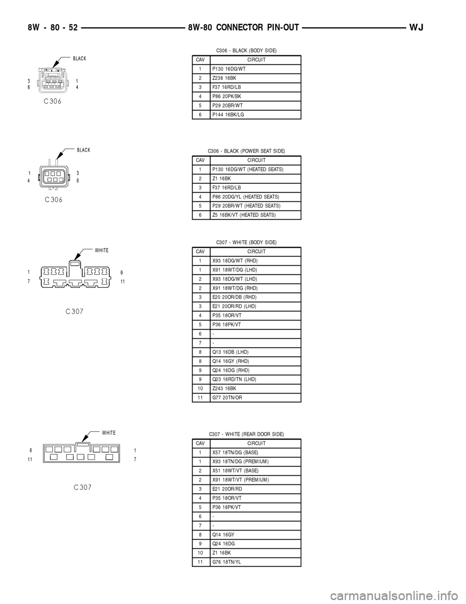
C306 - BLACK (BODY SIDE)
CAV CIRCUIT
1 P130 16DG/WT
2 Z238 16BK
3 F37 16RD/LB
4 P86 20PK/BK
5 P29 20BR/WT
6 P144 16BK/LG
C306 - BLACK (POWER SEAT SIDE)
CAV CIRCUIT
1 P130 16DG/WT (HEATED SEATS)
2 Z1 16BK
3 F37 16RD/LB
4 P86 20DG/YL (HEATED SEATS)
5 P29 20BR/WT (HEATED SEATS)
6 Z5 16BK/VT (HEATED SEATS)
C307 - WHITE (BODY SIDE)
CAV CIRCUIT
1 X93 18DG/WT (RHD)
1 X91 18WT/DG (LHD)
2 X93 18DG/WT (LHD)
2 X91 18WT/DG (RHD)
3 E20 20OR/DB (RHD)
3 E21 20OR/RD (LHD)
4 P35 18OR/VT
5 P36 18PK/VT
6-
7-
8 Q13 16DB (LHD)
8 Q14 16GY (RHD)
9 Q24 16DG (RHD)
9 Q23 16RD/TN (LHD)
10 Z243 16BK
11 G77 20TN/OR
C307 - WHITE (REAR DOOR SIDE)
CAV CIRCUIT
1 X57 18TN/DG (BASE)
1 X93 18TN/DG (PREMIUM)
2 X51 18WT/VT (BASE)
2 X91 18WT/VT (PREMIUM)
3 E21 20OR/RD
4 P35 18OR/VT
5 P36 18PK/VT
6-
7-
8 Q14 16GY
9 Q24 16DG
10 Z1 16BK
11 G76 18TN/YL
8W - 80 - 52 8W-80 CONNECTOR PIN-OUTWJ
Page 1263 of 2199
(2) Drain the coolant (Refer to 7 - COOLING -
STANDARD PROCEDURE) and disconnect the hoses
at the engine thermostat housing and the water
pump inlet. DO NOT waste reusable coolant. If the
solution is clean and is being drained only to service
the engine or cooling system, drain the coolant into a
clean container for reuse.
(3) Remove the air cleaner assembly (Refer to 9 -
ENGINE/AIR INTAKE SYSTEM/AIR CLEANER
HOUSING - REMOVAL).
(4) Remove the cylinder head cover (Refer to 9 -
ENGINE/CYLINDER HEAD/CYLINDER HEAD
COVER(S) - REMOVAL).
(5) Remove the capscrews, bridge and pivot assem-
blies and rocker arms (Refer to 9 - ENGINE/CYLIN-
DER HEAD/ROCKER ARM / ADJUSTER ASSY -
REMOVAL).
(6) Remove the push rods.Retain the push rods,
bridges, pivots and rocker arms in the same
order as removed.
(7) Remove the accessory drive belt (Refer to 7 -
COOLING/ACCESSORY DRIVE/DRIVE BELTS -
REMOVAL).
(8) Remove the A/C compressor mounting bolts
and secure the compressor to the side.
(9) Remove the power steering pump and bracket
from the intake manifold and water pump. Set the
pump and bracket aside. DO NOT disconnect the
hoses.
(10) Perform the Fuel System Pressure Release
procedure. (Refer to 14 - FUEL SYSTEM/FUEL
DELIVERY - STANDARD PROCEDURE).
(11) Disconnect the fuel supply line at the fuel rail.(12) Remove the intake and exhaust manifolds
from the engine cylinder head (Refer to 9 - ENGINE/
MANIFOLDS/INTAKE MANIFOLD - REMOVAL).
(13) Remove the coil rail (Refer to 8 - ELECTRI-
CAL/IGNITION CONTROL/COIL RAIL - REMOV-
AL).
(14) Remove spark plugs (Refer to 8 - ELECTRI-
CAL/IGNITION CONTROL/SPARK PLUG - REMOV-
AL).
(15) Disconnect the temperature sending unit wire
connector.
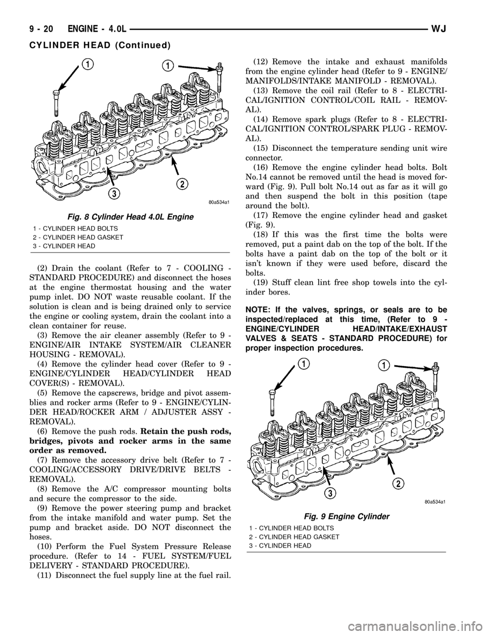
(16) Remove the engine cylinder head bolts. Bolt
No.14 cannot be removed until the head is moved for-
ward (Fig. 9). Pull bolt No.14 out as far as it will go
and then suspend the bolt in this position (tape
around the bolt).
(17) Remove the engine cylinder head and gasket
(Fig. 9).
(18) If this was the first time the bolts were
removed, put a paint dab on the top of the bolt. If the
bolts have a paint dab on the top of the bolt or it
isn't known if they were used before, discard the
bolts.
(19) Stuff clean lint free shop towels into the cyl-
inder bores.
NOTE: If the valves, springs, or seals are to be
inspected/replaced at this time, (Refer to 9 -
ENGINE/CYLINDER HEAD/INTAKE/EXHAUST
VALVES & SEATS - STANDARD PROCEDURE) for
proper inspection procedures.
Fig. 8 Cylinder Head 4.0L Engine
1 - CYLINDER HEAD BOLTS
2 - CYLINDER HEAD GASKET
3 - CYLINDER HEAD
Fig. 9 Engine Cylinder
1 - CYLINDER HEAD BOLTS
2 - CYLINDER HEAD GASKET
3 - CYLINDER HEAD
9 - 20 ENGINE - 4.0LWJ
CYLINDER HEAD (Continued)
Page 1331 of 2199
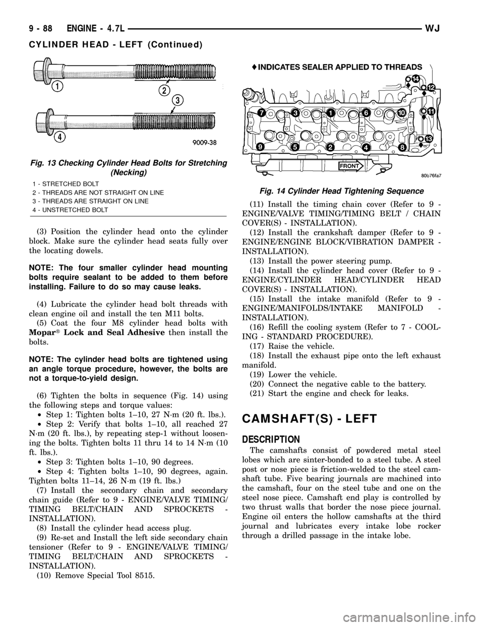
(3) Position the cylinder head onto the cylinder
block. Make sure the cylinder head seats fully over
the locating dowels.
NOTE: The four smaller cylinder head mounting
bolts require sealant to be added to them before
installing. Failure to do so may cause leaks.
(4) Lubricate the cylinder head bolt threads with
clean engine oil and install the ten M11 bolts.
(5) Coat the four M8 cylinder head bolts with
MopartLock and Seal Adhesivethen install the
bolts.
NOTE: The cylinder head bolts are tightened using
an angle torque procedure, however, the bolts are
not a torque-to-yield design.
(6) Tighten the bolts in sequence (Fig. 14) using
the following steps and torque values:
²Step 1: Tighten bolts 1±10, 27 N´m (20 ft. lbs.).
²Step 2: Verify that bolts 1±10, all reached 27
N´m (20 ft. lbs.), by repeating step-1 without loosen-
ing the bolts. Tighten bolts 11 thru 14 to 14 N´m (10
ft. lbs.).
²Step 3: Tighten bolts 1±10, 90 degrees.
²Step 4: Tighten bolts 1±10, 90 degrees, again.
Tighten bolts 11±14, 26 N´m (19 ft. lbs.)
(7) Install the secondary chain and secondary
chain guide (Refer to 9 - ENGINE/VALVE TIMING/
TIMING BELT/CHAIN AND SPROCKETS -
INSTALLATION).
(8) Install the cylinder head access plug.
(9) Re-set and Install the left side secondary chain
tensioner (Refer to 9 - ENGINE/VALVE TIMING/
TIMING BELT/CHAIN AND SPROCKETS -
INSTALLATION).
(10) Remove Special Tool 8515.(11) Install the timing chain cover (Refer to 9 -
ENGINE/VALVE TIMING/TIMING BELT / CHAIN
COVER(S) - INSTALLATION).
(12) Install the crankshaft damper (Refer to 9 -
ENGINE/ENGINE BLOCK/VIBRATION DAMPER -
INSTALLATION).
(13) Install the power steering pump.
(14) Install the cylinder head cover (Refer to 9 -
ENGINE/CYLINDER HEAD/CYLINDER HEAD
COVER(S) - INSTALLATION).
(15) Install the intake manifold (Refer to 9 -
ENGINE/MANIFOLDS/INTAKE MANIFOLD -
INSTALLATION).
(16) Refill the cooling system (Refer to 7 - COOL-
ING - STANDARD PROCEDURE).
(17) Raise the vehicle.
(18) Install the exhaust pipe onto the left exhaust
manifold.
(19) Lower the vehicle.
(20) Connect the negative cable to the battery.
(21) Start the engine and check for leaks.
CAMSHAFT(S) - LEFT
DESCRIPTION
The camshafts consist of powdered metal steel
lobes which are sinter-bonded to a steel tube. A steel
post or nose piece is friction-welded to the steel cam-
shaft tube. Five bearing journals are machined into
the camshaft, four on the steel tube and one on the
steel nose piece. Camshaft end play is controlled by
two thrust walls that border the nose piece journal.
Engine oil enters the hollow camshafts at the third
journal and lubricates every intake lobe rocker
through a drilled passage in the intake lobe.
Fig. 13 Checking Cylinder Head Bolts for Stretching
(Necking)
1 - STRETCHED BOLT
2 - THREADS ARE NOT STRAIGHT ON LINE
3 - THREADS ARE STRAIGHT ON LINE
4 - UNSTRETCHED BOLTFig. 14 Cylinder Head Tightening Sequence
9 - 88 ENGINE - 4.7LWJ
CYLINDER HEAD - LEFT (Continued)
Page 1957 of 2199
FRONT HEADREST SLEEVE
REMOVAL
(1) Remove head restraint (Refer to 23 - BODY/
SEATS/FRONT HEADREST - REMOVAL).
(2) Remove seat back cover (Refer to 23 - BODY/
SEATS/FRONT SEAT BACK COVER - REMOVAL).
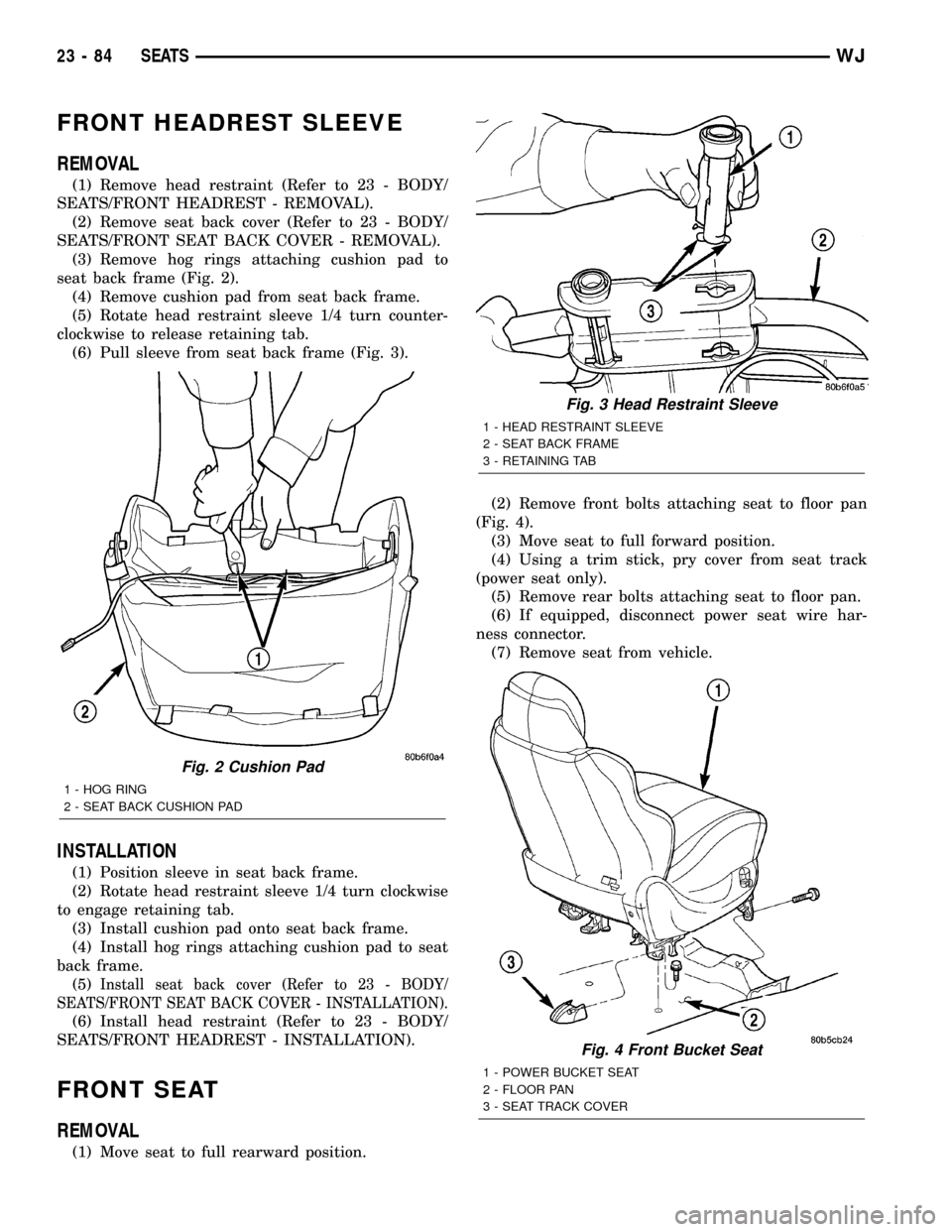
(3) Remove hog rings attaching cushion pad to
seat back frame (Fig. 2).
(4) Remove cushion pad from seat back frame.
(5) Rotate head restraint sleeve 1/4 turn counter-
clockwise to release retaining tab.
(6) Pull sleeve from seat back frame (Fig. 3).
INSTALLATION
(1) Position sleeve in seat back frame.
(2) Rotate head restraint sleeve 1/4 turn clockwise
to engage retaining tab.
(3) Install cushion pad onto seat back frame.
(4) Install hog rings attaching cushion pad to seat
back frame.
(5)
Install seat back cover (Refer to 23 - BODY/
SEATS/FRONT SEAT BACK COVER - INSTALLATION).
(6) Install head restraint (Refer to 23 - BODY/
SEATS/FRONT HEADREST - INSTALLATION).
FRONT SEAT
REMOVAL
(1) Move seat to full rearward position.(2) Remove front bolts attaching seat to floor pan
(Fig. 4).
(3) Move seat to full forward position.
(4) Using a trim stick, pry cover from seat track
(power seat only).
(5) Remove rear bolts attaching seat to floor pan.
(6) If equipped, disconnect power seat wire har-
ness connector.
(7) Remove seat from vehicle.
Fig. 2 Cushion Pad
1 - HOG RING
2 - SEAT BACK CUSHION PAD
Fig. 3 Head Restraint Sleeve
1 - HEAD RESTRAINT SLEEVE
2 - SEAT BACK FRAME
3 - RETAINING TAB
Fig. 4 Front Bucket Seat
1 - POWER BUCKET SEAT
2 - FLOOR PAN
3 - SEAT TRACK COVER
23 - 84 SEATSWJ