2002 JEEP GRAND CHEROKEE A Pillar
[x] Cancel search: A PillarPage 581 of 2199

INSTALLATION
WARNING: ON VEHICLES EQUIPPED WITH AIR-
BAGS, DISABLE THE SUPPLEMENTAL RESTRAINT
SYSTEM BEFORE ATTEMPTING ANY STEERING
WHEEL, STEERING COLUMN, DRIVER AIRBAG,
PASSENGER AIRBAG, FRONT IMPACT SENSOR,
SIDE IMPACT SENSOR, SIDE CURTAIN AIRBAG, OR
INSTRUMENT PANEL COMPONENT DIAGNOSIS OR
SERVICE. DISCONNECT AND ISOLATE THE BAT-
TERY NEGATIVE (GROUND) CABLE, THEN WAIT
TWO MINUTES FOR THE SYSTEM CAPACITOR TO
DISCHARGE BEFORE PERFORMING FURTHER
DIAGNOSIS OR SERVICE. THIS IS THE ONLY SURE
WAY TO DISABLE THE SUPPLEMENTALRESTRAINT SYSTEM. FAILURE TO TAKE THE
PROPER PRECAUTIONS COULD RESULT IN ACCI-
DENTAL AIRBAG DEPLOYMENT AND POSSIBLE
PERSONAL INJURY.
WARNING: THE SIDE IMPACT SENSOR ENABLES
THE SYSTEM TO DEPLOY THE SIDE CURTAIN AIR-
BAG. NEVER STRIKE OR DROP THE SIDE IMPACT
SENSOR, AS IT CAN DAMAGE THE IMPACT SEN-
SOR OR AFFECT ITS CALIBRATION. IF AN IMPACT
SENSOR IS ACCIDENTALLY DROPPED DURING
SERVICE, THE SENSOR MUST BE SCRAPPED AND
REPLACED WITH A NEW UNIT. FAILURE TO
OBSERVE THIS WARNING COULD RESULT IN ACCI-
DENTAL, INCOMPLETE, OR IMPROPER SIDE CUR-
TAIN AIRBAG DEPLOYMENT AND POSSIBLE
OCCUPANT INJURIES.
(1) Position the right or left side impact sensor
onto the B-pillar (Fig. 47).
(2) Install and tighten the two screws that secure
the right or left side impact sensor to the B-pillar.
Tighten the screws to 12 N´m (105 in. lbs.).
(3) Reconnect the airbag overlay wire harness con-
nector for the right or left side impact sensor to the
sensor connector receptacle.
(4) Reinstall the trim onto the lower right or left
B-pillar. (Refer to 23 - BODY/INTERIOR/B-PILLAR
LOWER TRIM - INSTALLATION).
(5) Do not reconnect the battery negative cable at
this time. The supplemental restraint system verifi-
cation test procedure should be performed following
service of any supplemental restraint system compo-
nent. (Refer to 8 - ELECTRICAL/RESTRAINTS -
STANDARD PROCEDURE - VERIFICATION TEST).
Fig. 47 Side Impact Sensor Remove/Install
1 - B-PILLAR
2 - SIDE IMPACT SENSOR
3 - SCREW (2)
4 - WIRE HARNESS CONNECTOR
8O - 44 RESTRAINTSWJ
SIDE IMPACT SENSOR (Continued)
Page 645 of 2199
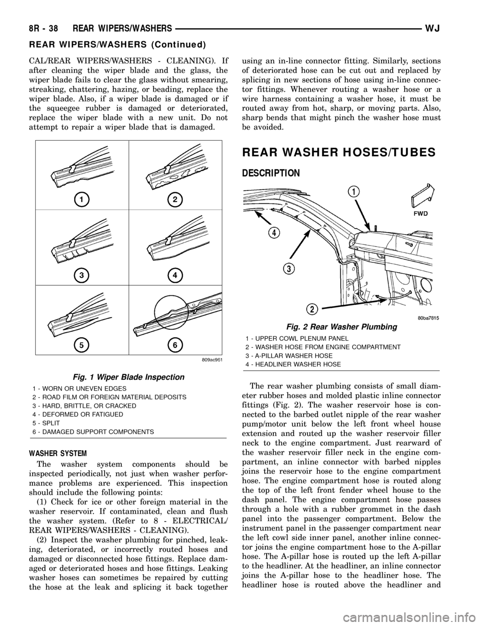
CAL/REAR WIPERS/WASHERS - CLEANING). If
after cleaning the wiper blade and the glass, the
wiper blade fails to clear the glass without smearing,
streaking, chattering, hazing, or beading, replace the
wiper blade. Also, if a wiper blade is damaged or if
the squeegee rubber is damaged or deteriorated,
replace the wiper blade with a new unit. Do not
attempt to repair a wiper blade that is damaged.
WASHER SYSTEM
The washer system components should be
inspected periodically, not just when washer perfor-
mance problems are experienced. This inspection
should include the following points:
(1) Check for ice or other foreign material in the
washer reservoir. If contaminated, clean and flush
the washer system. (Refer to 8 - ELECTRICAL/
REAR WIPERS/WASHERS - CLEANING).
(2) Inspect the washer plumbing for pinched, leak-
ing, deteriorated, or incorrectly routed hoses and
damaged or disconnected hose fittings. Replace dam-
aged or deteriorated hoses and hose fittings. Leaking
washer hoses can sometimes be repaired by cutting
the hose at the leak and splicing it back togetherusing an in-line connector fitting. Similarly, sections
of deteriorated hose can be cut out and replaced by
splicing in new sections of hose using in-line connec-
tor fittings. Whenever routing a washer hose or a
wire harness containing a washer hose, it must be
routed away from hot, sharp, or moving parts. Also,
sharp bends that might pinch the washer hose must
be avoided.
REAR WASHER HOSES/TUBES
DESCRIPTION
The rear washer plumbing consists of small diam-
eter rubber hoses and molded plastic inline connector
fittings (Fig. 2). The washer reservoir hose is con-
nected to the barbed outlet nipple of the rear washer
pump/motor unit below the left front wheel house
extension and routed up the washer reservoir filler
neck to the engine compartment. Just rearward of
the washer reservoir filler neck in the engine com-
partment, an inline connector with barbed nipples
joins the reservoir hose to the engine compartment
hose. The engine compartment hose is routed along
the top of the left front fender wheel house to the
dash panel. The engine compartment hose passes
through a hole with a rubber grommet in the dash
panel into the passenger compartment. Below the
instrument panel in the passenger compartment near
the left cowl side inner panel, another inline connec-
tor joins the engine compartment hose to the A-pillar
hose. The A-pillar hose is routed up the left A-pillar
to the headliner. At the headliner, an inline connector
joins the A-pillar hose to the headliner hose. The
headliner hose is routed above the headliner and
Fig. 1 Wiper Blade Inspection
1 - WORN OR UNEVEN EDGES
2 - ROAD FILM OR FOREIGN MATERIAL DEPOSITS
3 - HARD, BRITTLE, OR CRACKED
4 - DEFORMED OR FATIGUED
5 - SPLIT
6 - DAMAGED SUPPORT COMPONENTS
Fig. 2 Rear Washer Plumbing
1 - UPPER COWL PLENUM PANEL
2 - WASHER HOSE FROM ENGINE COMPARTMENT
3 - A-PILLAR WASHER HOSE
4 - HEADLINER WASHER HOSE
8R - 38 REAR WIPERS/WASHERSWJ
REAR WIPERS/WASHERS (Continued)
Page 1178 of 2199
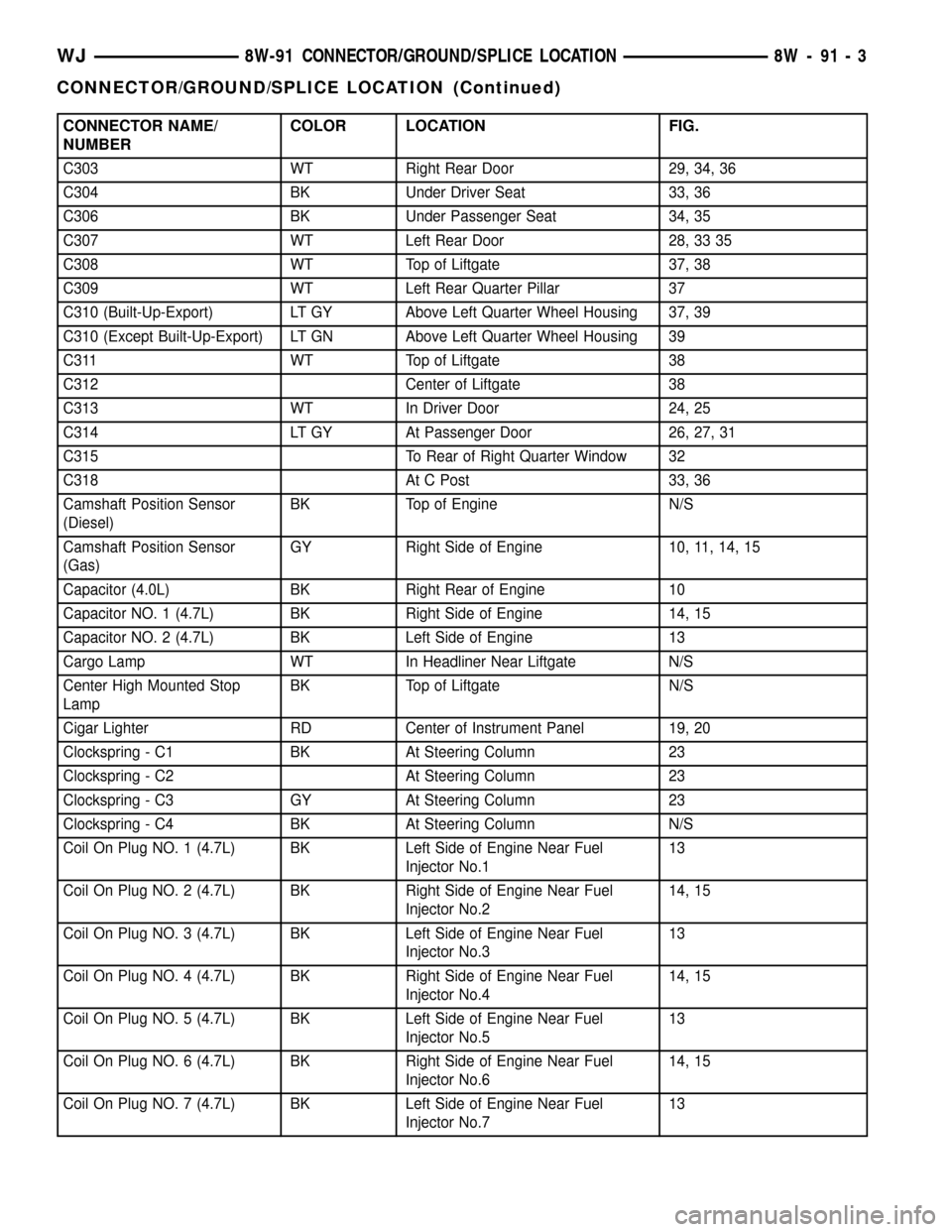
CONNECTOR NAME/
NUMBERCOLOR LOCATION FIG.
C303 WT Right Rear Door 29, 34, 36
C304 BK Under Driver Seat 33, 36
C306 BK Under Passenger Seat 34, 35
C307 WT Left Rear Door 28, 33 35
C308 WT Top of Liftgate 37, 38
C309 WT Left Rear Quarter Pillar 37
C310 (Built-Up-Export) LT GY Above Left Quarter Wheel Housing 37, 39
C310 (Except Built-Up-Export) LT GN Above Left Quarter Wheel Housing 39
C311 WT Top of Liftgate 38
C312 Center of Liftgate 38
C313 WT In Driver Door 24, 25
C314 LT GY At Passenger Door 26, 27, 31
C315 To Rear of Right Quarter Window 32
C318 At C Post 33, 36
Camshaft Position Sensor
(Diesel)BK Top of Engine N/S
Camshaft Position Sensor
(Gas)GY Right Side of Engine 10, 11, 14, 15
Capacitor (4.0L) BK Right Rear of Engine 10
Capacitor NO. 1 (4.7L) BK Right Side of Engine 14, 15
Capacitor NO. 2 (4.7L) BK Left Side of Engine 13
Cargo Lamp WT In Headliner Near Liftgate N/S
Center High Mounted Stop
LampBK Top of Liftgate N/S
Cigar Lighter RD Center of Instrument Panel 19, 20
Clockspring - C1 BK At Steering Column 23
Clockspring - C2 At Steering Column 23
Clockspring - C3 GY At Steering Column 23
Clockspring - C4 BK At Steering Column N/S
Coil On Plug NO. 1 (4.7L) BK Left Side of Engine Near Fuel
Injector No.113
Coil On Plug NO. 2 (4.7L) BK Right Side of Engine Near Fuel
Injector No.214, 15
Coil On Plug NO. 3 (4.7L) BK Left Side of Engine Near Fuel
Injector No.313
Coil On Plug NO. 4 (4.7L) BK Right Side of Engine Near Fuel
Injector No.414, 15
Coil On Plug NO. 5 (4.7L) BK Left Side of Engine Near Fuel
Injector No.513
Coil On Plug NO. 6 (4.7L) BK Right Side of Engine Near Fuel
Injector No.614, 15
Coil On Plug NO. 7 (4.7L) BK Left Side of Engine Near Fuel
Injector No.713
WJ8W-91 CONNECTOR/GROUND/SPLICE LOCATION 8W - 91 - 3
CONNECTOR/GROUND/SPLICE LOCATION (Continued)
Page 1181 of 2199
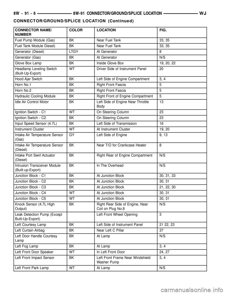
CONNECTOR NAME/
NUMBERCOLOR LOCATION FIG.
Fuel Pump Module (Gas) BK Near Fuel Tank 33, 35
Fuel Tank Module Diesel) BK Near Fuel Tank 33, 35
Generator (Diesel) LTGY At Generator 8
Generator (Gas) BK At Generator N/S
Glove Box Lamp BK Inside Glove Box 19, 20, 22
Headlamp Leveling Switch
(Built-Up-Export)WT Driver Side of Instrument Panel 20
Hood Ajar Switch BK Left Side of Engine Compartment 3, 4
Horn No.1 BK Right Front Fascia 5
Horn No.2 BK Right Front Fascia 5
Hydraulic Cooling Module BK Right Front of Engine Compartment 5
Idle Air Control Motor BK Left Side of Engine Near Throttle
Body13
Ignition Switch - C1 WT On Steering Column 23
Ignition Switch - C2 BK On Steering Column 23
Input Speed Sensor (4.7L) BK Left Side of Transmission 16
Instrument Cluster WT At Instrument Cluster 19, 20
Intake Air Temperature Sensor
(Gas)GY Left Side of Engine 9, 13
Intake Air Temperature Sensor
(Diesel)BK Near T/O for Crankcase Heater 8
Intake Port Swirl Actuator
(Diesel)BK Right Rear of Engine Compartment N/S
Intrusion Transceiver Module
(Built-up-Export)BK In The Overhead N/S
Junction Block - C1 BK At Junction Block 30, 31, 33
Junction Block - C2 BK At Junction Block 30, 31
Junction Block - C3 BK At Junction Block 21, 22, 30
Junction Block - C4 WT At Junction Block 30, 31
Junction Block - C5 WT At Junction Block 30, 31
Knock Sensor (4.7L High
Output)BK Right Rear Side of Engine, Near
Coil on Plug No.8N/S
Leak Detection Pump (Except
Built-Up-Export)Left Front Wheel Opening 3
Left Courtesy Lamp BK Left Side of Instrument Panel 21 22, 23
Left Curtain Airbag BK Near Left C Pillar 37
Left Door Handle Courtesy
LampBK At Lamp N/S
Left Fog Lamp BK At Lamp 3, 4
Left Front Door Speaker WT In Left Front Door 24, 27
Left Front Impact Sensor BK Left Front Frame Near Windshield
Washer Pump3, 4
Left Front Park Lamp WT At Lamp N/S
8W - 91 - 6 8W-91 CONNECTOR/GROUND/SPLICE LOCATIONWJ
CONNECTOR/GROUND/SPLICE LOCATION (Continued)
Page 1184 of 2199
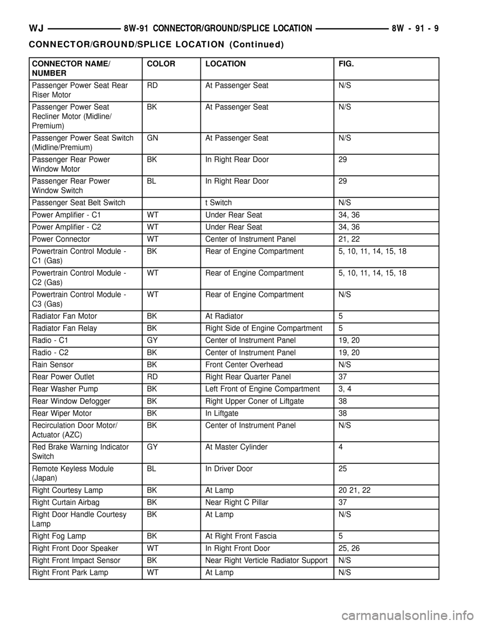
CONNECTOR NAME/
NUMBERCOLOR LOCATION FIG.
Passenger Power Seat Rear
Riser MotorRD At Passenger Seat N/S
Passenger Power Seat
Recliner Motor (Midline/
Premium)BK At Passenger Seat N/S
Passenger Power Seat Switch
(Midline/Premium)GN At Passenger Seat N/S
Passenger Rear Power
Window MotorBK In Right Rear Door 29
Passenger Rear Power
Window SwitchBL In Right Rear Door 29
Passenger Seat Belt Switch t Switch N/S
Power Amplifier - C1 WT Under Rear Seat 34, 36
Power Amplifier - C2 WT Under Rear Seat 34, 36
Power Connector WT Center of Instrument Panel 21, 22
Powertrain Control Module -
C1 (Gas)BK Rear of Engine Compartment 5, 10, 11, 14, 15, 18
Powertrain Control Module -
C2 (Gas)WT Rear of Engine Compartment 5, 10, 11, 14, 15, 18
Powertrain Control Module -
C3 (Gas)WT Rear of Engine Compartment N/S
Radiator Fan Motor BK At Radiator 5
Radiator Fan Relay BK Right Side of Engine Compartment 5
Radio - C1 GY Center of Instrument Panel 19, 20
Radio - C2 BK Center of Instrument Panel 19, 20
Rain Sensor BK Front Center Overhead N/S
Rear Power Outlet RD Right Rear Quarter Panel 37
Rear Washer Pump BK Left Front of Engine Compartment 3, 4
Rear Window Defogger BK Right Upper Coner of Liftgate 38
Rear Wiper Motor BK In Liftgate 38
Recirculation Door Motor/
Actuator (AZC)BK Center of Instrument Panel N/S
Red Brake Warning Indicator
SwitchGY At Master Cylinder 4
Remote Keyless Module
(Japan)BL In Driver Door 25
Right Courtesy Lamp BK At Lamp 20 21, 22
Right Curtain Airbag BK Near Right C Pillar 37
Right Door Handle Courtesy
LampBK At Lamp N/S
Right Fog Lamp BK At Right Front Fascia 5
Right Front Door Speaker WT In Right Front Door 25, 26
Right Front Impact Sensor BK Near Right Verticle Radiator Support N/S
Right Front Park Lamp WT At Lamp N/S
WJ8W-91 CONNECTOR/GROUND/SPLICE LOCATION 8W - 91 - 9
CONNECTOR/GROUND/SPLICE LOCATION (Continued)
Page 1191 of 2199
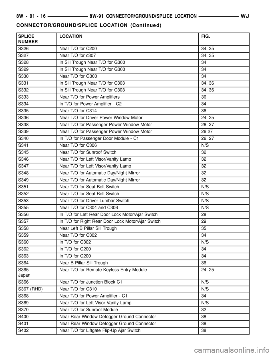
SPLICE
NUMBERLOCATION FIG.
S326 Near T/O for C200 34, 35
S327 Near T/O for c307 34, 35
S328 In Sill Trough Near T/O for G300 34
S329 In Sill Trough Near T/O for G300 34
S330 Near T/O for G300 34
S331 In Sill Trough Near T/O for C303 34, 36
S332 In Sill Trough Near T/O for C303 34, 36
S333 Near T/O for Power Amplifiers 36
S334 In T/O for Power Amplifier - C2 34
S335 Near T/O for C314 36
S336 Near T/O for Driver Power Window Motor 24, 25
S338 Near T/O for Passenger Power Window Motor 26, 27
S339 Near T/O for Passenger Power Window Motor 26 27
S340 In T/O for Passenger Door Module - C1 26, 27
S341 Near T/O for C306 N/S
S345 Near T/O for Sunroof Switch 32
S346 Near T/O for Left Visor/Vanity Lamp 32
S347 Near T/O for Left Visor/Vanity Lamp 32
S348 Near T/O for Automatic Day/Night Mirror 32
S349 Near T/O for Automatic Day/Night Mirror 32
S351 Near T/O for Seat Belt Switch N/S
S352 Near T/O for Seat Belt Switch N/S
S353 Near T/O for Driver Lumbar Switch N/S
S355 Near T/O for C304 and C306 N/S
S356 In T/O for Left Rear Door Lock Motor/Ajar Switch 28
S357 In T/O for Right Rear Door Lock Motor/Ajar Switch 29
S358 Near Left B Pillar Sill Trough 35
S359 Near T/O for C302 34
S360 In T/O for C302 N/S
S362 In T/O for C200 34
S363 In T/O for C200 34
S364 Near B Pillar Sill Trough 36
S365
JapanNear T/O for Remote Keyless Entry Module 24, 25
S366 Near T/O for Junction Block C1 N/S
S367 (RHD) Near T/O for C310 N/S
S368 Near T/O for Power Amplifier - C1 34
S369 Near T/O for Left Visor Vanity Lamp N/S
S370 Near T/O for Sunroof Module 32
S400 Near Rear Window Defogger Ground Connector 38
S401 Near Rear Window Defogger Ground Connector 38
S402 Near T/O for Liftgate Flip-Up Ajar Switch 38
8W - 91 - 16 8W-91 CONNECTOR/GROUND/SPLICE LOCATIONWJ
CONNECTOR/GROUND/SPLICE LOCATION (Continued)
Page 1241 of 2199
FuseandBatteryin the index in this service man-
ual for the location of additional service information
covering the ignition-off draw fuse and the battery.
FUSE COVER
REMOVAL
(1) Disconnect and isolate the battery negative
cable.
(2) Pull down on the rear edge (nearest the rear of
the vehicle) of the instrument panel fuse cover until
the rear latches unsnap from the tabs on the lower
junction block housing and the side latch unsnaps
from the tab on the instrument panel steering col-
umn support bracket outboard of the 16-way data
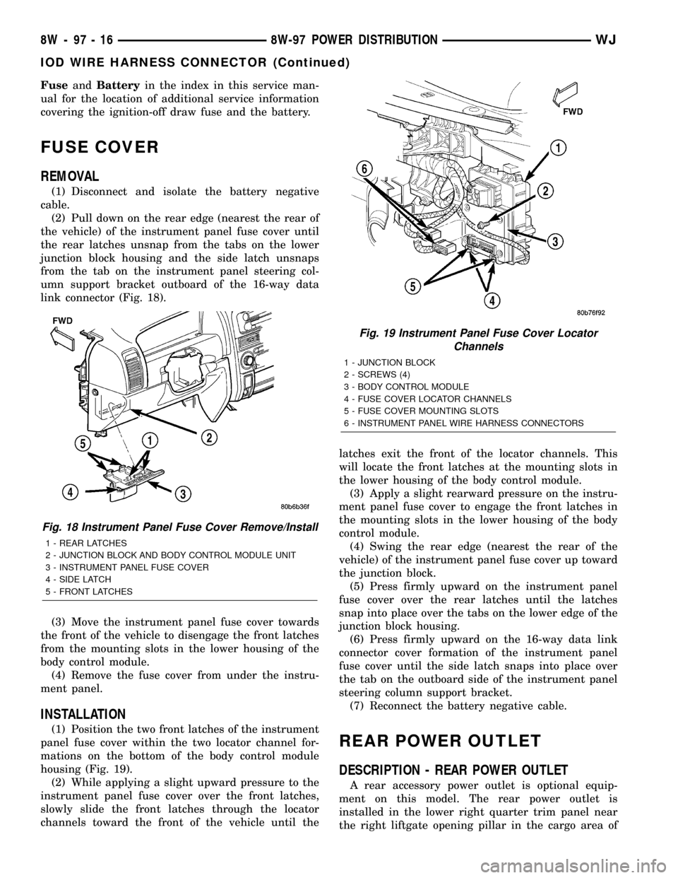
link connector (Fig. 18).
(3) Move the instrument panel fuse cover towards
the front of the vehicle to disengage the front latches
from the mounting slots in the lower housing of the
body control module.
(4) Remove the fuse cover from under the instru-
ment panel.
INSTALLATION
(1) Position the two front latches of the instrument
panel fuse cover within the two locator channel for-
mations on the bottom of the body control module
housing (Fig. 19).
(2) While applying a slight upward pressure to the
instrument panel fuse cover over the front latches,
slowly slide the front latches through the locator
channels toward the front of the vehicle until thelatches exit the front of the locator channels. This
will locate the front latches at the mounting slots in
the lower housing of the body control module.
(3) Apply a slight rearward pressure on the instru-
ment panel fuse cover to engage the front latches in
the mounting slots in the lower housing of the body
control module.
(4) Swing the rear edge (nearest the rear of the
vehicle) of the instrument panel fuse cover up toward
the junction block.
(5) Press firmly upward on the instrument panel
fuse cover over the rear latches until the latches
snap into place over the tabs on the lower edge of the
junction block housing.
(6) Press firmly upward on the 16-way data link
connector cover formation of the instrument panel
fuse cover until the side latch snaps into place over
the tab on the outboard side of the instrument panel
steering column support bracket.
(7) Reconnect the battery negative cable.
REAR POWER OUTLET
DESCRIPTION - REAR POWER OUTLET
A rear accessory power outlet is optional equip-
ment on this model. The rear power outlet is
installed in the lower right quarter trim panel near
the right liftgate opening pillar in the cargo area of
Fig. 18 Instrument Panel Fuse Cover Remove/Install
1 - REAR LATCHES
2 - JUNCTION BLOCK AND BODY CONTROL MODULE UNIT
3 - INSTRUMENT PANEL FUSE COVER
4 - SIDE LATCH
5 - FRONT LATCHES
Fig. 19 Instrument Panel Fuse Cover Locator
Channels
1 - JUNCTION BLOCK
2 - SCREWS (4)
3 - BODY CONTROL MODULE
4 - FUSE COVER LOCATOR CHANNELS
5 - FUSE COVER MOUNTING SLOTS
6 - INSTRUMENT PANEL WIRE HARNESS CONNECTORS
8W - 97 - 16 8W-97 POWER DISTRIBUTIONWJ
IOD WIRE HARNESS CONNECTOR (Continued)
Page 1414 of 2199
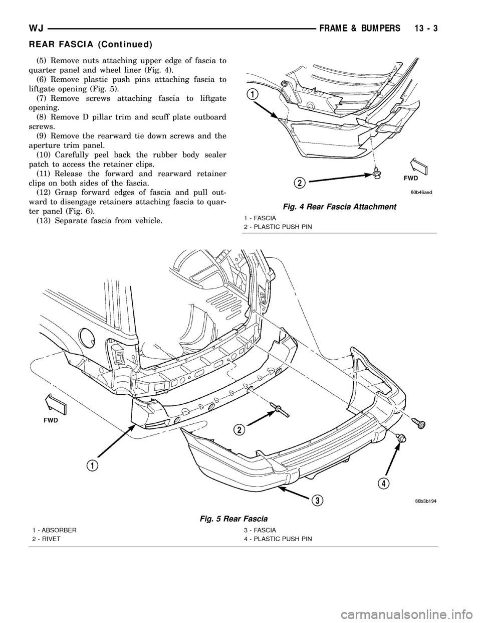
(5) Remove nuts attaching upper edge of fascia to
quarter panel and wheel liner (Fig. 4).
(6) Remove plastic push pins attaching fascia to
liftgate opening (Fig. 5).
(7) Remove screws attaching fascia to liftgate
opening.
(8) Remove D pillar trim and scuff plate outboard
screws.
(9) Remove the rearward tie down screws and the
aperture trim panel.
(10) Carefully peel back the rubber body sealer
patch to access the retainer clips.
(11) Release the forward and rearward retainer
clips on both sides of the fascia.
(12) Grasp forward edges of fascia and pull out-
ward to disengage retainers attaching fascia to quar-
ter panel (Fig. 6).
(13) Separate fascia from vehicle.
Fig. 5 Rear Fascia
1 - ABSORBER
2 - RIVET3 - FASCIA
4 - PLASTIC PUSH PIN
Fig. 4 Rear Fascia Attachment
1 - FASCIA
2 - PLASTIC PUSH PIN
WJFRAME & BUMPERS 13 - 3
REAR FASCIA (Continued)