2002 JEEP GRAND CHEROKEE 4.0
[x] Cancel search: 4.0Page 1519 of 2199
INSTALLATION
NOTE: The pulley is marked front for installation.
CAUTION: On vehicles equipped with the 4.0L or
4.7L, Do not reuse the old power steering pump
pulley it is not intended for reuse. A new pulley
must be installed if removed.
(1) Replace pulley if bent, cracked, or loose.
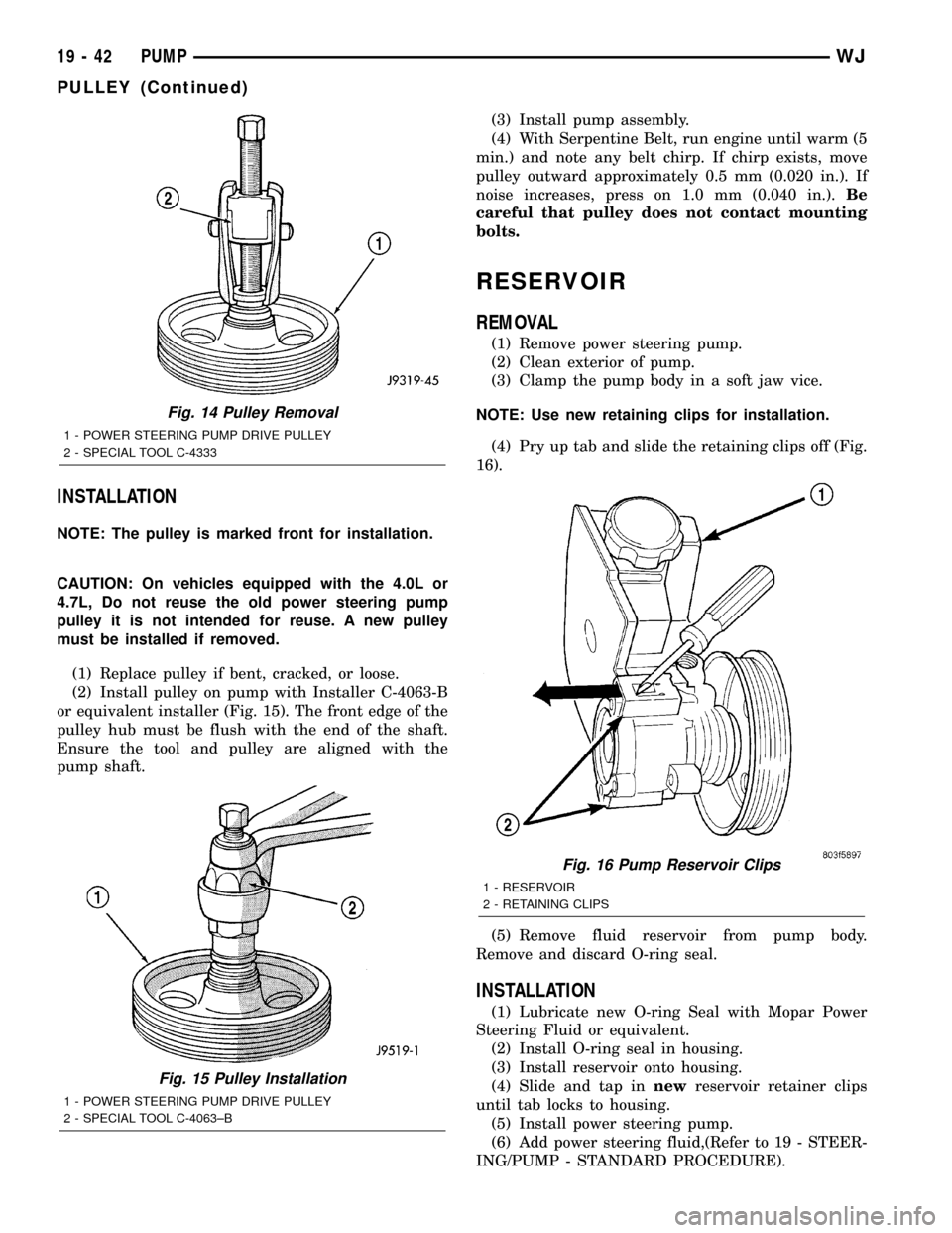
(2) Install pulley on pump with Installer C-4063-B
or equivalent installer (Fig. 15). The front edge of the
pulley hub must be flush with the end of the shaft.
Ensure the tool and pulley are aligned with the
pump shaft.(3) Install pump assembly.
(4) With Serpentine Belt, run engine until warm (5
min.) and note any belt chirp. If chirp exists, move
pulley outward approximately 0.5 mm (0.020 in.). If
noise increases, press on 1.0 mm (0.040 in.).Be
careful that pulley does not contact mounting
bolts.
RESERVOIR
REMOVAL
(1) Remove power steering pump.
(2) Clean exterior of pump.
(3) Clamp the pump body in a soft jaw vice.
NOTE: Use new retaining clips for installation.
(4) Pry up tab and slide the retaining clips off (Fig.
16).
(5) Remove fluid reservoir from pump body.
Remove and discard O-ring seal.
INSTALLATION
(1) Lubricate new O-ring Seal with Mopar Power
Steering Fluid or equivalent.
(2) Install O-ring seal in housing.
(3) Install reservoir onto housing.
(4) Slide and tap innewreservoir retainer clips
until tab locks to housing.
(5) Install power steering pump.
(6) Add power steering fluid,(Refer to 19 - STEER-
ING/PUMP - STANDARD PROCEDURE).
Fig. 14 Pulley Removal
1 - POWER STEERING PUMP DRIVE PULLEY
2 - SPECIAL TOOL C-4333
Fig. 15 Pulley Installation
1 - POWER STEERING PUMP DRIVE PULLEY
2 - SPECIAL TOOL C-4063±B
Fig. 16 Pump Reservoir Clips
1 - RESERVOIR
2 - RETAINING CLIPS
19 - 42 PUMPWJ
PULLEY (Continued)
Page 1546 of 2199

REMOVAL
The overdrive unit can be removed and serviced
separately. It is not necessary to remove the entire
transmission assembly to perform overdrive unit
repairs.
If only the overdrive unit requires service, refer to
Overdrive Removal for proper procedures.
CAUTION: The transmission and torque converter
must be removed as an assembly to avoid compo-
nent damage. The converter driveplate, pump bush-
ing, or oil seal can be damaged if the converter is
left attached to the driveplate during removal. Be
sure to remove the transmission and converter as
an assembly.
(1) Disconnect battery negative cable.
(2) Disconnect and lower or remove necessary
exhaust components.
(3) Disconnect fluid cooler lines at transmission.
(4) Remove starter motor. (Refer to 8 - ELECTRI-
CAL/STARTING/STARTER MOTOR - REMOVAL)
(5) Disconnect and remove crankshaft position sen-
sor. (Refer to 14 - FUEL SYSTEM/FUEL INJEC-
TION/CRANKSHAFT POSITION SENSOR -
REMOVAL) Retain sensor attaching bolts.
CAUTION: The crankshaft position sensor will be
damaged if the transmission is removed, or
installed, while the sensor is still bolted to the
engine block, or transmission (4.0L only). To avoid
damage, be sure to remove the sensor before
removing the transmission.
(6) Remove the bolts holding the bell housing
brace to the transmission.
(7) Remove nut holding the bell housing brace to
the engine to transmission bending brace.
(8) Remove the bell housing brace from the trans-
mission (Fig. 13).
(9) Remove the bolt holding the torque converter
cover to the transmission.
(10) Remove the torque converter cover from the
transmission.
(11) If transmission is being removed for overhaul,
remove transmission oil pan, drain fluid and reinstall
pan.
(12) Remove fill tube bracket bolts and pull tube
out of transmission. Retain fill tube seal. On4x4
models, it will also be necessary to remove bolt
attaching transfer case vent tube to converter hous-
ing.
(13) Rotate crankshaft in clockwise direction until
converter bolts are accessible. Then remove bolts one
at a time. Rotate crankshaft with socket wrench on
dampener bolt.(14) Mark propeller shaft and axle yokes for
assembly alignment. Then disconnect and remove
propeller shaft. On4x4models, remove both propel-
ler shafts.
(15) Disconnect wires from park/neutral position
switch and transmission solenoid.
(16) Disconnect gearshift cable from transmission
manual valve lever (Fig. 14).
Fig. 13 Bell Housing Brace and Converter Cover
1 - Transmission
2 - Torque Converter Cover
3 - Bellhousing Brace
Fig. 14 Transmission Shift Cable
1 - SHIFT CABLE
2 - MANUAL LEVER
3 - MANUAL LEVER
WJAUTOMATIC TRANSMISSION - 42RE 21 - 27
AUTOMATIC TRANSMISSION - 42RE (Continued)
Page 1590 of 2199

PROCEDURE TWO
(1) Start engine and apply parking brake.
(2) Shift the transmission into DRIVE for approxi-
mately 2 seconds.
(3) Shift the transmission into REVERSE for
approximately 2 seconds.
(4) Shift the transmission into PARK.
(5) Hook up DRBtscan tool and select engine.
(6) Select sensors.
(7) Read the transmission temperature value.
(8) Compare the fluid temperature value with the
figure. (Fig. 88)
(9) Adjust transmission fluid level shown on the
dipstick according to the figure.NOTE: After adding any fluid to the transmission,
wait a minimum of 2 minutes for the oil to fully
drain from the fill tube into the transmission before
rechecking the fluid level.
(10) Check transmission for leaks.
STANDARD PROCEDURE - FLUID AND FILTER
REPLACEMENT
For proper service intervals (Refer to LUBRICA-
TION & MAINTENANCE/MAINTENANCE SCHED-
ULES - DESCRIPTION). The service fluid fill after a
filter change is approximately 3.8 liters (4.0 quarts).
REMOVAL
(1) Hoist and support vehicle on safety stands.
(2) Place a large diameter shallow drain pan
beneath the transmission pan.
(3) Remove bolts holding front and sides of pan to
transmission (Fig. 89).
(4) Loosen bolts holding rear of pan to transmis-
sion.
(5) Slowly separate front of pan and gasket away
from transmission allowing the fluid to drain into
drain pan.
(6) Hold up pan and remove remaining bolt hold-
ing pan to transmission.
Fig. 88 42/44RE Fluid Fill Graph
Fig. 87 Dipstick Fluid Level Marks - Typical
1 - DIPSTICK
2 - MAXIMUM CORRECT FLUID LEVEL
3 - ACCEPTABLE FLUID LEVEL
WJAUTOMATIC TRANSMISSION - 42RE 21 - 71
FLUID AND FILTER (Continued)
Page 1863 of 2199
STANDARD PROCEDURE - MATCH MOUNTING
Tires and wheels are currently not match mounted
at the factory. Match mounting is a technique used to
reduce runout in the wheel/tire assembly. This means
that the high spot of the tire is aligned with the low
spot on the wheel rim. The high spot on the tire is
marked with a paint mark or a bright colored adhe-
sive label on the outboard sidewall. The low spot on
the rim is identified with a label on the outside of the
rim and a dot on the inside of the rim. If the outside
label has been removed the tire will have to be
removed to locate the dot on the inside of the rim.
Before dismounting a tire from its wheel, a refer-
ence mark should be placed on the tire at the valve
stem location. This reference will ensure that it is
remounted in the original position on the wheel.
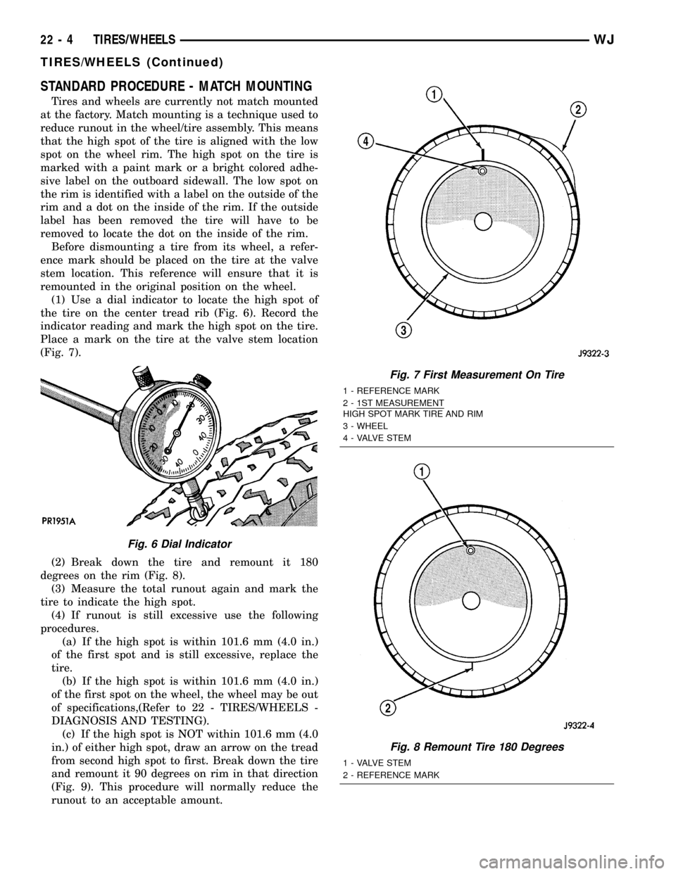
(1) Use a dial indicator to locate the high spot of
the tire on the center tread rib (Fig. 6). Record the
indicator reading and mark the high spot on the tire.
Place a mark on the tire at the valve stem location
(Fig. 7).
(2) Break down the tire and remount it 180
degrees on the rim (Fig. 8).
(3) Measure the total runout again and mark the
tire to indicate the high spot.
(4) If runout is still excessive use the following
procedures.
(a) If the high spot is within 101.6 mm (4.0 in.)
of the first spot and is still excessive, replace the
tire.
(b) If the high spot is within 101.6 mm (4.0 in.)
of the first spot on the wheel, the wheel may be out
of specifications,(Refer to 22 - TIRES/WHEELS -
DIAGNOSIS AND TESTING).
(c) If the high spot is NOT within 101.6 mm (4.0
in.) of either high spot, draw an arrow on the tread
from second high spot to first. Break down the tire
and remount it 90 degrees on rim in that direction
(Fig. 9). This procedure will normally reduce the
runout to an acceptable amount.
Fig. 6 Dial Indicator
Fig. 7 First Measurement On Tire
1 - REFERENCE MARK
2 - 1ST MEASUREMENT
HIGH SPOT MARK TIRE AND RIM
3 - WHEEL
4 - VALVE STEM
Fig. 8 Remount Tire 180 Degrees
1 - VALVE STEM
2 - REFERENCE MARK
22 - 4 TIRES/WHEELSWJ
TIRES/WHEELS (Continued)
Page 1868 of 2199
CLEANING
Remove the protective coating on the tires before
delivery of a vehicle. This coating may cause deteri-
oration of the tires.
To remove the protective coating, apply warm
water and let it soak for a few minutes. Afterwards,
scrub the coating away with a soft bristle brush.
Steam cleaning may also be used to remove the coat-
ing.
NOTE: DO NOT use gasoline, mineral oil, oil-based
solvent or a wire brush for cleaning.
SPECIFICATIONS
TIRES
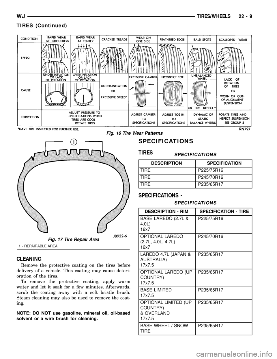
SPECIFICATIONS
DESCRIPTION SPECIFICATION
TIRE P225/75R16
TIRE P245/70R16
TIRE P235/65R17
SPECIFICATIONS -
SPECIFICATIONS
DESCRIPTION - RIM SPECIFICATION - TIRE
BASE LAREDO (2.7L &
4.0L)
16x7P225/75R16
OPTIONAL LAREDO
(2.7L, 4.0L, 4.7L)
16x7P245/70R16
LAREDO 4.7L (JAPAN &
AUSTRALIA)
17x7.5P235/65R17
OPTIONAL LAREDO (UP
COUNTRY)
17x7.5P235/65R17
BASE LIMITED
17x7.5P235/65R17
OPTIONAL LIMITED (UP
COUNTRY)
& OVERLAND
17x7.5P235/65R17
BASE WHEEL / SNOW
TIREP235/65R17
Fig. 16 Tire Wear Patterns
Fig. 17 Tire Repair Area
1 - REPAIRABLE AREA
WJTIRES/WHEELS 22 - 9
TIRES (Continued)
Page 2085 of 2199
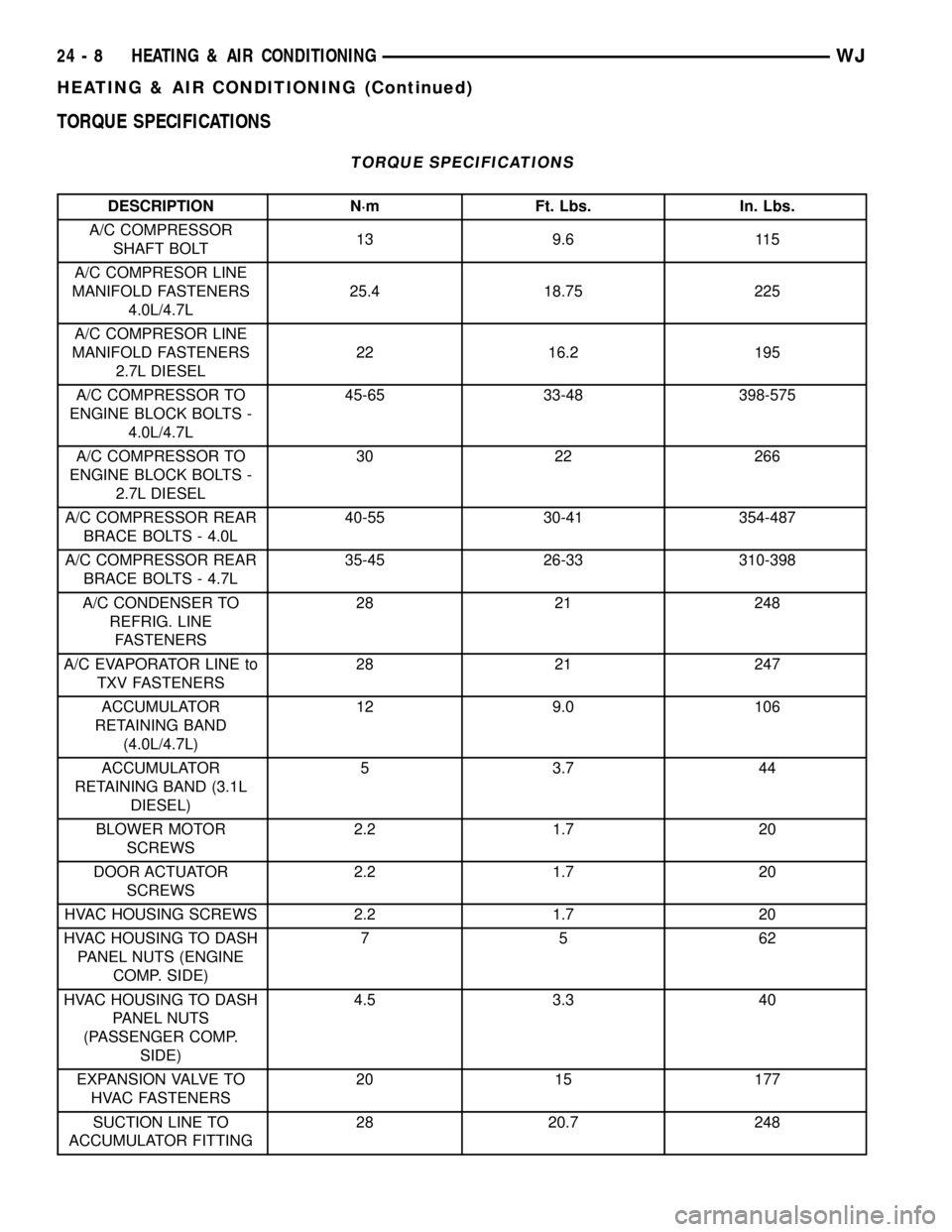
TORQUE SPECIFICATIONS
TORQUE SPECIFICATIONS
DESCRIPTION N´m Ft. Lbs. In. Lbs.
A/C COMPRESSOR
SHAFT BOLT13 9.6 115
A/C COMPRESOR LINE
MANIFOLD FASTENERS
4.0L/4.7L25.4 18.75 225
A/C COMPRESOR LINE
MANIFOLD FASTENERS
2.7L DIESEL22 16.2 195
A/C COMPRESSOR TO
ENGINE BLOCK BOLTS -
4.0L/4.7L45-65 33-48 398-575
A/C COMPRESSOR TO
ENGINE BLOCK BOLTS -
2.7L DIESEL30 22 266
A/C COMPRESSOR REAR
BRACE BOLTS - 4.0L40-55 30-41 354-487
A/C COMPRESSOR REAR
BRACE BOLTS - 4.7L35-45 26-33 310-398
A/C CONDENSER TO
REFRIG. LINE
FASTENERS28 21 248
A/C EVAPORATOR LINE to
TXV FASTENERS28 21 247
ACCUMULATOR
RETAINING BAND
(4.0L/4.7L)12 9.0 106
ACCUMULATOR
RETAINING BAND (3.1L
DIESEL)5 3.7 44
BLOWER MOTOR
SCREWS2.2 1.7 20
DOOR ACTUATOR
SCREWS2.2 1.7 20
HVAC HOUSING SCREWS 2.2 1.7 20
HVAC HOUSING TO DASH
PANEL NUTS (ENGINE
COMP. SIDE)75 62
HVAC HOUSING TO DASH
PANEL NUTS
(PASSENGER COMP.
SIDE)4.5 3.3 40
EXPANSION VALVE TO
HVAC FASTENERS20 15 177
SUCTION LINE TO
ACCUMULATOR FITTING28 20.7 248
24 - 8 HEATING & AIR CONDITIONINGWJ
HEATING & AIR CONDITIONING (Continued)
Page 2136 of 2199
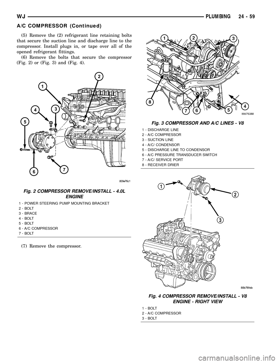
(5) Remove the (2) refrigerant line retaining bolts
that secure the suction line and discharge line to the
compressor. Install plugs in, or tape over all of the
opened refrigerant fittings.
(6) Remove the bolts that secure the compressor
(Fig. 2) or (Fig. 3) and (Fig. 4).
(7) Remove the compressor.
Fig. 2 COMPRESSOR REMOVE/INSTALL - 4.0L
ENGINE
1 - POWER STEERING PUMP MOUNTING BRACKET
2 - BOLT
3 - BRACE
4 - BOLT
5 - BOLT
6 - A/C COMPRESSOR
7 - BOLT
Fig. 3 COMPRESSOR AND A/C LINES - V8
1 - DISCHARGE LINE
2 - A/C COMPRESSOR
3 - SUCTION LINE
4 - A/C/ CONDENSOR
5 - DISCHARGE LINE TO CONDENSOR
6 - A/C PRESSURE TRANSDUCER SWITCH
7 - A/C/ SERVICE PORT
8 - RECEIVER DRIER
Fig. 4 COMPRESSOR REMOVE/INSTALL - V8
ENGINE - RIGHT VIEW
1 - BOLT
2 - A/C COMPRESSOR
3 - BOLT
WJPLUMBING 24 - 59
A/C COMPRESSOR (Continued)
Page 2138 of 2199

INSTALLATION
INSTALLATION
WARNING: REVIEW THE WARNINGS AND CAU-
TIONS IN THE FRONT OF THIS SECTION BEFORE
PERFORMING THE FOLLOWING OPERATION.
(Refer to 24 - HEATING & AIR CONDITIONING/
PLUMBING - WARNING) (Refer to 24 - HEATING &
AIR CONDITIONING/PLUMBING - CAUTION)
Any kinks or sharp bends in the refrigerant plumb-
ing will reduce the capacity of the entire air condi-
tioning system. Kinks and sharp bends reduce the
flow of refrigerant in the system. A good rule for the
flexible hose refrigerant lines is to keep the radius of
all bends at least ten times the diameter of the hose.
In addition, the flexible hose refrigerant lines should
be routed so they are at least 80 millimeters (3
inches) from the exhaust manifold.
High pressures are produced in the refrigerant sys-
tem when the air conditioning compressor is operat-
ing. Extreme care must be exercised to make sure
that each of the refrigerant system connections is
pressure-tight and leak free. It is a good practice to
inspect all flexible hose refrigerant lines at least once
a year to make sure they are in good condition and
properly routed.
NOTE: If a replacement compressor is being
installed, be certain to check the refrigerant oil
level. (Refer to 24 - HEATING & AIR CONDITIONING/
PLUMBING/REFRIGERANT OIL - STANDARD PRO-
CEDURE) Use only refrigerant oil of the type
recommended for the compressor in the vehicle.
(Refer to 24 - HEATING & AIR CONDITIONING/
PLUMBING/REFRIGERANT OIL - DESCRIPTION)
(1) Install the compressor. Tighten the 4.0L
mounting bolts fastening the compressor to the block
to 45-65 N´m (35-50 ft. lbs.). Tighten the mounting
bolts holding the rear brace to the compressor and
block to 40-55 N´m (30-40 ft. lbs.). Tighten the 4.7L
compressor front mounting screws to 45-65 N´m
(35-50 ft. lbs.), and the rear mounting screws to
35-45 N´m (25-35 ft. lbs.).
(2) Remove the tape or plugs from all of the
opened refrigerant line fittings. Install the suction
line and discharge line fittings to the manifold on the
compressor. Tighten the mounting bolts to 25.4 N´m
(225 in. lbs.).
(3) Install the serpentine drive belt. Refer to Cool-
ing for the procedures.
(4) Plug in the compressor clutch coil wire harness
connector.
(5) Connect the battery negative cable.(6) Evacuate the refrigerant system. (Refer to 24 -
HEATING & AIR CONDITIONING/PLUMBING -
STANDARD PROCEDURE - REFRIGERANT SYS-
TEM EVACUATE)
(7) Charge the refrigerant system. (Refer to 24 -
HEATING & AIR CONDITIONING/PLUMBING -
STANDARD PROCEDURE - REFRIGERANT SYS-
TEM CHARGE)
INSTALLATION - 2.7L TURBO DIESEL
CAUTION: Check the oil level before installing the
new compressor. (Refer to 24 - HEATING & AIR
CONDITIONING/PLUMBING/REFRIGERANT OIL -
STANDARD PROCEDURE)
WARNING: REVIEW THE WARNINGS AND CAU-
TIONS IN THE FRONT OF THIS SECTION BEFORE
PERFORMING THE FOLLOWING OPERATION.
(Refer to 24 - HEATING & AIR CONDITIONING/
PLUMBING - WARNING) (Refer to 24 - HEATING &
AIR CONDITIONING/PLUMBING - CAUTION)
Any kinks or sharp bends in the refrigerant plumb-
ing will reduce the capacity of the entire air condi-
tioning system. Kinks and sharp bends reduce the
flow of refrigerant in the system. A good rule for the
flexible hose refrigerant lines is to keep the radius of
all bends at least ten times the diameter of the hose.
In addition, the flexible hose refrigerant lines should
be routed so they are at least 80 millimeters (3
inches) from the exhaust manifold.
High pressures are produced in the refrigerant sys-
tem when the air conditioning compressor is operat-
ing. Extreme care must be exercised to make sure
that each of the refrigerant system connections is
pressure-tight and leak free. It is a good practice to
inspect all flexible hose refrigerant lines at least once
a year to make sure they are in good condition and
properly routed.
(1) Lift the compressor into position and install
the (4) mounting bolts. Torque the bolts to 41 N´m
(30 ft. lbs.).
(2) Connect the compressor clutch electrical con-
nector.
(3) Install both refrigerant lines on the compressor.
Make certain the sealing 0-rings are free of tears and
well lubricated with R-134a refrigerant oil. Torque
the line retaining bolts to 22 N´m (200 in. lbs.).
(4) Install the front splash shield (if equipped).
(5) Lower the vehicle from the hoist.
(6) Install the accessory drive belt on the compres-
sor clutch. Refer to Cooling for the procedure.
(7) Evacuate the refrigerant system. (Refer to 24 -
HEATING & AIR CONDITIONING/PLUMBING -
WJPLUMBING 24 - 61
A/C COMPRESSOR (Continued)