2002 JEEP GRAND CHEROKEE Fuel
[x] Cancel search: FuelPage 2005 of 2199

Fig. 20 BODYSIDE APERTURE AND REAR WHEELHOUSE
Fig. 21 FUEL FILLER GUSSET
23 - 132 BODY STRUCTUREWJ
SEALER LOCATIONS (Continued)
Page 2010 of 2199

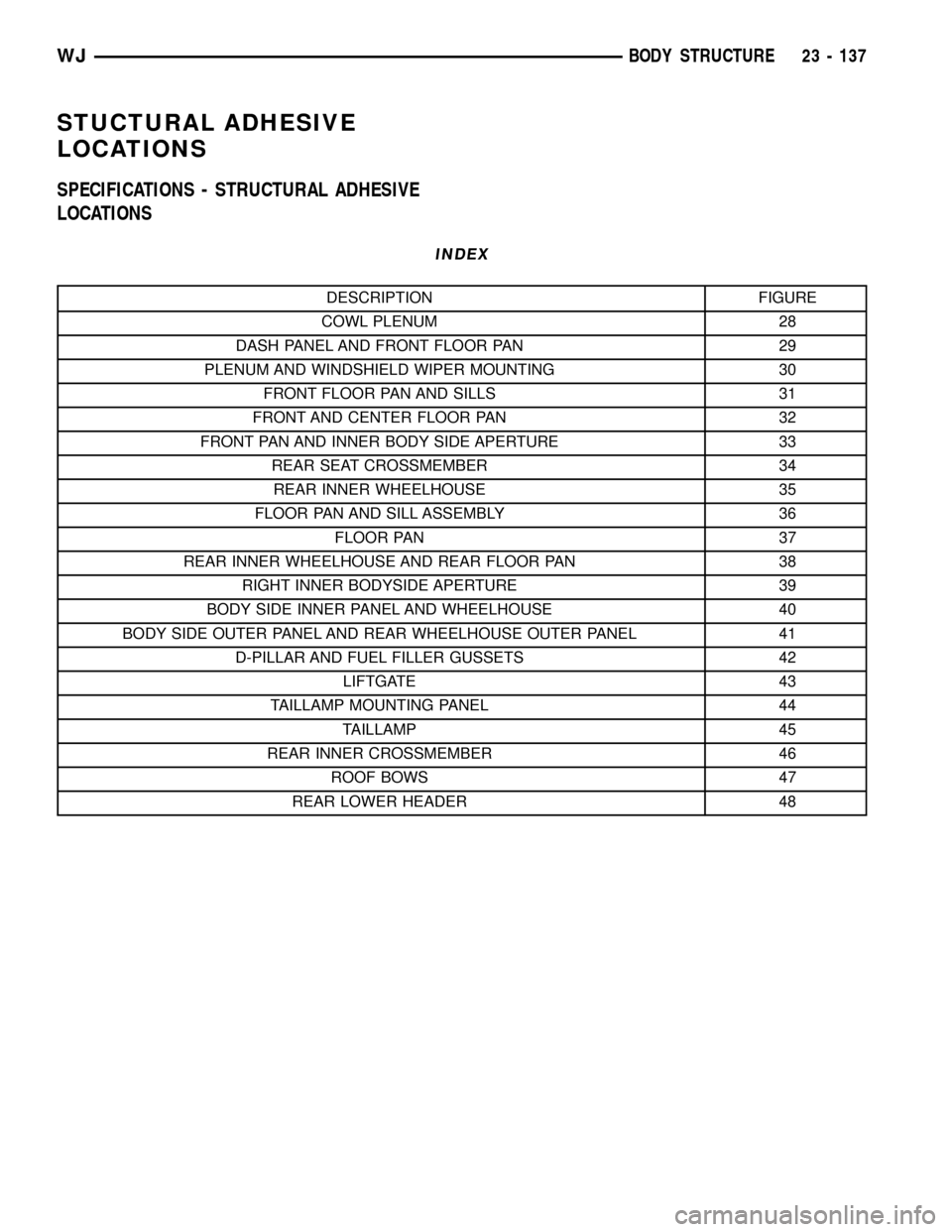
STUCTURAL ADHESIVE
LOCATIONS
SPECIFICATIONS - STRUCTURAL ADHESIVE
LOCATIONS
INDEX
DESCRIPTION FIGURE
COWL PLENUM 28
DASH PANEL AND FRONT FLOOR PAN 29
PLENUM AND WINDSHIELD WIPER MOUNTING 30
FRONT FLOOR PAN AND SILLS 31
FRONT AND CENTER FLOOR PAN 32
FRONT PAN AND INNER BODY SIDE APERTURE 33
REAR SEAT CROSSMEMBER 34
REAR INNER WHEELHOUSE 35
FLOOR PAN AND SILL ASSEMBLY 36
FLOOR PAN 37
REAR INNER WHEELHOUSE AND REAR FLOOR PAN 38
RIGHT INNER BODYSIDE APERTURE 39
BODY SIDE INNER PANEL AND WHEELHOUSE 40
BODY SIDE OUTER PANEL AND REAR WHEELHOUSE OUTER PANEL 41
D-PILLAR AND FUEL FILLER GUSSETS 42
LIFTGATE 43
TAILLAMP MOUNTING PANEL 44
TAILLAMP 45
REAR INNER CROSSMEMBER 46
ROOF BOWS 47
REAR LOWER HEADER 48
WJBODY STRUCTURE 23 - 137
Page 2020 of 2199

Fig. 42 D-PILLAR AND FUEL FILLER GUSSETS
WJBODY STRUCTURE 23 - 147
STUCTURAL ADHESIVE LOCATIONS (Continued)
Page 2027 of 2199

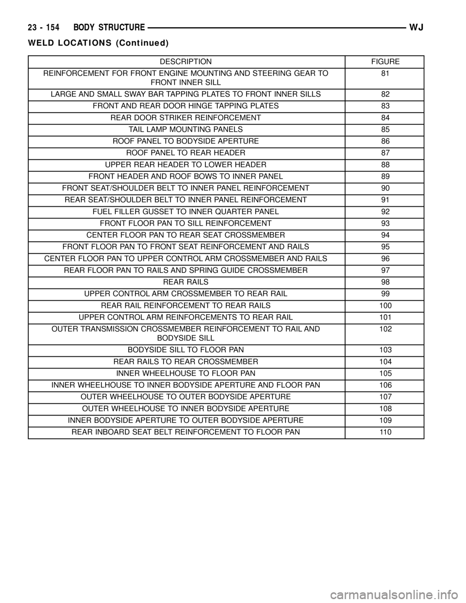
DESCRIPTION FIGURE
REINFORCEMENT FOR FRONT ENGINE MOUNTING AND STEERING GEAR TO
FRONT INNER SILL81
LARGE AND SMALL SWAY BAR TAPPING PLATES TO FRONT INNER SILLS 82
FRONT AND REAR DOOR HINGE TAPPING PLATES 83
REAR DOOR STRIKER REINFORCEMENT 84
TAIL LAMP MOUNTING PANELS 85
ROOF PANEL TO BODYSIDE APERTURE 86
ROOF PANEL TO REAR HEADER 87
UPPER REAR HEADER TO LOWER HEADER 88
FRONT HEADER AND ROOF BOWS TO INNER PANEL 89
FRONT SEAT/SHOULDER BELT TO INNER PANEL REINFORCEMENT 90
REAR SEAT/SHOULDER BELT TO INNER PANEL REINFORCEMENT 91
FUEL FILLER GUSSET TO INNER QUARTER PANEL 92
FRONT FLOOR PAN TO SILL REINFORCEMENT 93
CENTER FLOOR PAN TO REAR SEAT CROSSMEMBER 94
FRONT FLOOR PAN TO FRONT SEAT REINFORCEMENT AND RAILS 95
CENTER FLOOR PAN TO UPPER CONTROL ARM CROSSMEMBER AND RAILS 96
REAR FLOOR PAN TO RAILS AND SPRING GUIDE CROSSMEMBER 97
REAR RAILS 98
UPPER CONTROL ARM CROSSMEMBER TO REAR RAIL 99
REAR RAIL REINFORCEMENT TO REAR RAILS 100
UPPER CONTROL ARM REINFORCEMENTS TO REAR RAIL 101
OUTER TRANSMISSION CROSSMEMBER REINFORCEMENT TO RAIL AND
BODYSIDE SILL102
BODYSIDE SILL TO FLOOR PAN 103
REAR RAILS TO REAR CROSSMEMBER 104
INNER WHEELHOUSE TO FLOOR PAN 105
INNER WHEELHOUSE TO INNER BODYSIDE APERTURE AND FLOOR PAN 106
OUTER WHEELHOUSE TO OUTER BODYSIDE APERTURE 107
OUTER WHEELHOUSE TO INNER BODYSIDE APERTURE 108
INNER BODYSIDE APERTURE TO OUTER BODYSIDE APERTURE 109
REAR INBOARD SEAT BELT REINFORCEMENT TO FLOOR PAN 110
23 - 154 BODY STRUCTUREWJ
WELD LOCATIONS (Continued)
Page 2063 of 2199

Fig. 91 REAR SEAT/SHOULDER BELT TO INNER PANEL REINFORCEMENT
Fig. 92 FUEL FILLER GUSSET TO INNER QUARTER PANEL
23 - 190 BODY STRUCTUREWJ
WELD LOCATIONS (Continued)
Page 2156 of 2199

EMISSIONS CONTROL
TABLE OF CONTENTS
page page
EMISSIONS CONTROL
DESCRIPTION
DESCRIPTION - EMISSION CONTROL
SYSTEM.............................1
DESCRIPTION - STATE DISPLAY TEST
MODE...............................2
DESCRIPTION - CIRCUIT ACTUATION TEST
MODE...............................2
DESCRIPTION - DIAGNOSTIC TROUBLE
CODES..............................2DESCRIPTION - TASK MANAGER.........17
DESCRIPTION - MONITORED SYSTEMS . . . 17
DESCRIPTION - TRIP DEFINITION........19
DESCRIPTION - COMPONENT MONITORS . . 19
DESCRIPTION - NON-MONITORED
CIRCUITS...........................20
DESCRIPTION - HIGH AND LOW LIMITS . . . 20
DESCRIPTION - LOAD VALUE...........20
OPERATION - TASK MANAGER............21
EVAPORATIVE EMISSIONS................24
EMISSIONS CONTROL
DESCRIPTION
DESCRIPTION - EMISSION CONTROL SYSTEM
The Powertrain Control Module (PCM) monitors
many different circuits in the fuel injection, ignition,
emission and engine systems. If the PCM senses a prob-
lem with a monitored circuit often enough to indicate an
actual problem, it stores a Diagnostic Trouble Code
(DTC) in the PCM's memory. If the code applies to a
non-emissions related component or system, and the
problem is repaired or ceases to exist, the PCM cancels
the code after 40 warm-up cycles. Diagnostic trouble
codes that affect vehicle emissions illuminate the Mal-
function Indicator (check engine) Lamp. Refer to Mal-
function Indicator Lamp in this section.
Certain criteria must be met before the PCM
stores a DTC in memory. The criteria may be a spe-
cific range of engine RPM, engine temperature,
and/or input voltage to the PCM.
The PCM might not store a DTC for a monitored cir-
cuit even though a malfunction has occurred. This may
happen because one of the DTC criteria for the circuit
has not been met.For example
,assume the diagnostic
trouble code criteria requires the PCM to monitor the
circuit only when the engine operates between 750 and
2000 RPM. Suppose the sensor's output circuit shorts to
ground when engine operates above 2400 RPM (result-
ing in 0 volt input to the PCM). Because the condition
happens at an engine speed above the maximum thresh-
old (2000 rpm), the PCM will not store a DTC.
There are several operating conditions for which
the PCM monitors and sets DTC's. Refer to Moni-
tored Systems, Components, and Non-Monitored Cir-
cuits in this section.Technicians must retrieve stored DTC's by connect-
ing the DRB scan tool (or an equivalent scan tool) to
the 16±way data link connector (Fig. 1).
NOTE: Various diagnostic procedures may actually
cause a diagnostic monitor to set a DTC. For
instance, pulling a spark plug wire to perform a
spark test may set the misfire code. When a repair
is completed and verified, connect the DRB scan
tool to the 16±way data link connector to erase all
DTC's and extinguish the MIL (check engine lamp).Fig. 1 Data Link (Diagnostic) Connector Location
1 - INSTRUMENT PANEL LOWER/LEFT EDGE
2 - DATA LINK CONNECTOR
WJEMISSIONS CONTROL 25 - 1
Page 2157 of 2199

DESCRIPTION - STATE DISPLAY TEST MODE
The switch inputs to the Powertrain Control Mod-
ule (PCM) have two recognized states; HIGH and
LOW. For this reason, the PCM cannot recognize the
difference between a selected switch position versus
an open circuit, a short circuit, or a defective switch.
If the State Display screen shows the change from
HIGH to LOW or LOW to HIGH, assume the entire
switch circuit to the PCM functions properly. Connect
the DRB scan tool to the data link connector and
access the state display screen. Then access either
State Display Inputs and Outputs or State Display
Sensors.
DESCRIPTION - CIRCUIT ACTUATION TEST
MODE
The Circuit Actuation Test Mode checks for proper
operation of output circuits or devices the Powertrain
Control Module (PCM) may not internally recognize.
The PCM attempts to activate these outputs and
allow an observer to verify proper operation. Most of
the tests provide an audible or visual indication of
device operation (click of relay contacts, fuel spray,
etc.). Except for intermittent conditions, if a device
functions properly during testing, assume the device,
its associated wiring, and driver circuit work cor-
rectly. Connect the DRB scan tool to the data link
connector and access the Actuators screen.
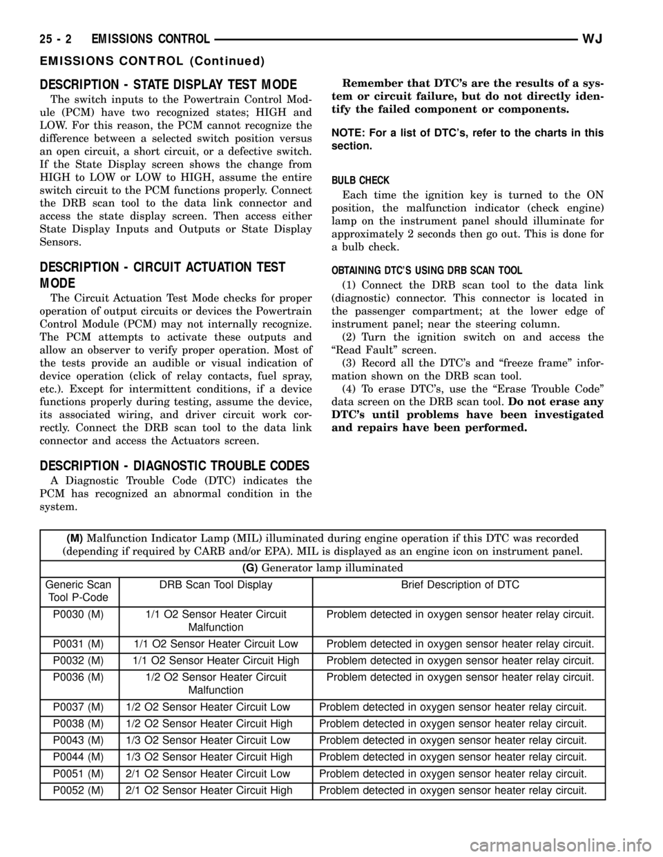
DESCRIPTION - DIAGNOSTIC TROUBLE CODES
A Diagnostic Trouble Code (DTC) indicates the
PCM has recognized an abnormal condition in the
system.Remember that DTC's are the results of a sys-
tem or circuit failure, but do not directly iden-
tify the failed component or components.
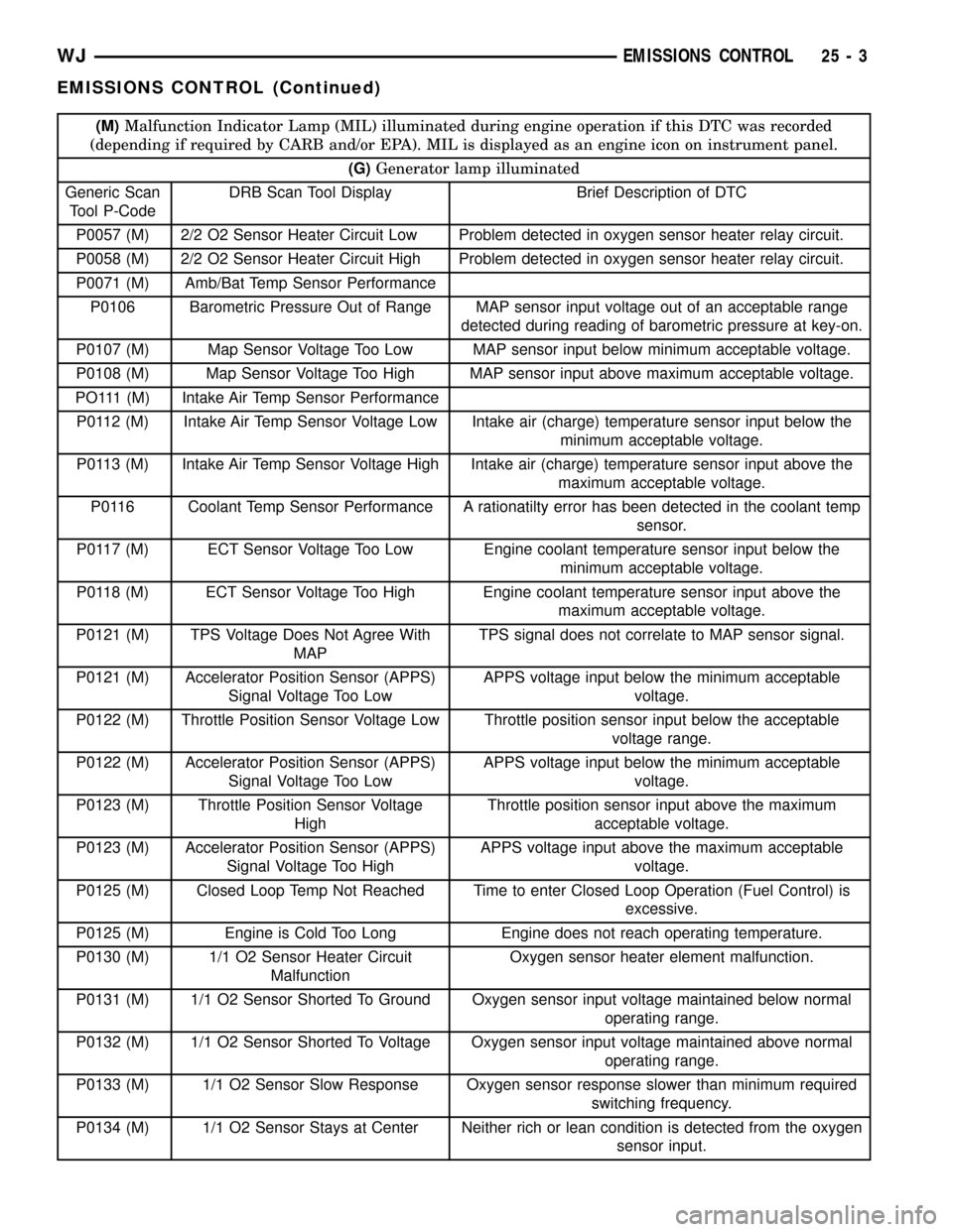
NOTE: For a list of DTC's, refer to the charts in this
section.
BULB CHECK
Each time the ignition key is turned to the ON
position, the malfunction indicator (check engine)
lamp on the instrument panel should illuminate for
approximately 2 seconds then go out. This is done for
a bulb check.
OBTAINING DTC'S USING DRB SCAN TOOL
(1) Connect the DRB scan tool to the data link
(diagnostic) connector. This connector is located in
the passenger compartment; at the lower edge of
instrument panel; near the steering column.
(2) Turn the ignition switch on and access the
ªRead Faultº screen.
(3) Record all the DTC's and ªfreeze frameº infor-
mation shown on the DRB scan tool.
(4) To erase DTC's, use the ªErase Trouble Codeº
data screen on the DRB scan tool.Do not erase any
DTC's until problems have been investigated
and repairs have been performed.
(M)Malfunction Indicator Lamp (MIL) illuminated during engine operation if this DTC was recorded
(depending if required by CARB and/or EPA). MIL is displayed as an engine icon on instrument panel.
(G)Generator lamp illuminated
Generic Scan
Tool P-CodeDRB Scan Tool Display Brief Description of DTC
P0030 (M) 1/1 O2 Sensor Heater Circuit
MalfunctionProblem detected in oxygen sensor heater relay circuit.
P0031 (M) 1/1 O2 Sensor Heater Circuit Low Problem detected in oxygen sensor heater relay circuit.
P0032 (M) 1/1 O2 Sensor Heater Circuit High Problem detected in oxygen sensor heater relay circuit.
P0036 (M) 1/2 O2 Sensor Heater Circuit
MalfunctionProblem detected in oxygen sensor heater relay circuit.
P0037 (M) 1/2 O2 Sensor Heater Circuit Low Problem detected in oxygen sensor heater relay circuit.
P0038 (M) 1/2 O2 Sensor Heater Circuit High Problem detected in oxygen sensor heater relay circuit.
P0043 (M) 1/3 O2 Sensor Heater Circuit Low Problem detected in oxygen sensor heater relay circuit.
P0044 (M) 1/3 O2 Sensor Heater Circuit High Problem detected in oxygen sensor heater relay circuit.
P0051 (M) 2/1 O2 Sensor Heater Circuit Low Problem detected in oxygen sensor heater relay circuit.
P0052 (M) 2/1 O2 Sensor Heater Circuit High Problem detected in oxygen sensor heater relay circuit.
25 - 2 EMISSIONS CONTROLWJ
EMISSIONS CONTROL (Continued)
Page 2158 of 2199

(M)Malfunction Indicator Lamp (MIL) illuminated during engine operation if this DTC was recorded
(depending if required by CARB and/or EPA). MIL is displayed as an engine icon on instrument panel.
(G)Generator lamp illuminated
Generic Scan
Tool P-CodeDRB Scan Tool Display Brief Description of DTC
P0057 (M) 2/2 O2 Sensor Heater Circuit Low Problem detected in oxygen sensor heater relay circuit.
P0058 (M) 2/2 O2 Sensor Heater Circuit High Problem detected in oxygen sensor heater relay circuit.
P0071 (M) Amb/Bat Temp Sensor Performance
P0106 Barometric Pressure Out of Range MAP sensor input voltage out of an acceptable range
detected during reading of barometric pressure at key-on.
P0107 (M) Map Sensor Voltage Too Low MAP sensor input below minimum acceptable voltage.
P0108 (M) Map Sensor Voltage Too High MAP sensor input above maximum acceptable voltage.
PO111 (M) Intake Air Temp Sensor Performance
P0112 (M) Intake Air Temp Sensor Voltage Low Intake air (charge) temperature sensor input below the
minimum acceptable voltage.
P0113 (M) Intake Air Temp Sensor Voltage High Intake air (charge) temperature sensor input above the
maximum acceptable voltage.
P0116 Coolant Temp Sensor Performance A rationatilty error has been detected in the coolant temp
sensor.
P0117 (M) ECT Sensor Voltage Too Low Engine coolant temperature sensor input below the
minimum acceptable voltage.
P0118 (M) ECT Sensor Voltage Too High Engine coolant temperature sensor input above the
maximum acceptable voltage.
P0121 (M) TPS Voltage Does Not Agree With
MAPTPS signal does not correlate to MAP sensor signal.
P0121 (M) Accelerator Position Sensor (APPS)
Signal Voltage Too LowAPPS voltage input below the minimum acceptable
voltage.
P0122 (M) Throttle Position Sensor Voltage Low Throttle position sensor input below the acceptable
voltage range.
P0122 (M) Accelerator Position Sensor (APPS)
Signal Voltage Too LowAPPS voltage input below the minimum acceptable
voltage.
P0123 (M) Throttle Position Sensor Voltage
HighThrottle position sensor input above the maximum
acceptable voltage.
P0123 (M) Accelerator Position Sensor (APPS)
Signal Voltage Too HighAPPS voltage input above the maximum acceptable
voltage.
P0125 (M) Closed Loop Temp Not Reached Time to enter Closed Loop Operation (Fuel Control) is
excessive.
P0125 (M) Engine is Cold Too Long Engine does not reach operating temperature.
P0130 (M) 1/1 O2 Sensor Heater Circuit
MalfunctionOxygen sensor heater element malfunction.
P0131 (M) 1/1 O2 Sensor Shorted To Ground Oxygen sensor input voltage maintained below normal
operating range.
P0132 (M) 1/1 O2 Sensor Shorted To Voltage Oxygen sensor input voltage maintained above normal
operating range.
P0133 (M) 1/1 O2 Sensor Slow Response Oxygen sensor response slower than minimum required
switching frequency.
P0134 (M) 1/1 O2 Sensor Stays at Center Neither rich or lean condition is detected from the oxygen
sensor input.
WJEMISSIONS CONTROL 25 - 3
EMISSIONS CONTROL (Continued)