2002 JEEP GRAND CHEROKEE Fuel
[x] Cancel search: FuelPage 1783 of 2199

A solenoid can also be described by the method by
which it is controlled. Some of the possibilities
include variable force, pulse-width modulated, con-
stant ON, or duty cycle. The variable force and pulse-
width modulated versions utilize similar methods to
control the current flow through the solenoid to posi-
tion the solenoid plunger at a desired position some-
where between full ON and full OFF. The constant
ON and duty cycled versions control the voltage
across the solenoid to allow either full flow or no flow
through the solenoid's valve.
OPERATION
When an electrical current is applied to the sole-
noid coil, a magnetic field is created which produces
an attraction to the plunger, causing the plunger to
move and work against the spring pressure and the
load applied by the fluid the valve is controlling. The
plunger is normally directly attached to the valve
which it is to operate. When the current is removed
from the coil, the attraction is removed and the
plunger will return to its original position due to
spring pressure.
The plunger is made of a conductive material and
accomplishes this movement by providing a path for
the magnetic field to flow. By keeping the air gap
between the plunger and the coil to the minimum
necessary to allow free movement of the plunger, the
magnetic field is maximized.
TORQUE CONVERTER
DESCRIPTION
The torque converter (Fig. 109) is a hydraulic
device that couples the engine crankshaft to the
transmission. The torque converter consists of an
outer shell with an internal turbine, a stator, an
overrunning clutch, an impeller and an electronically
applied converter clutch. The converter clutch pro-vides reduced engine speed and greater fuel economy
when engaged. Clutch engagement also provides
reduced transmission fluid temperatures. The con-
verter clutch engages in third gear. The torque con-
verter hub drives the transmission oil (fluid) pump
and contains an o-ring seal to better control oil flow.
The torque converter is a sealed, welded unit that
is not repairable and is serviced as an assembly.
CAUTION: The torque converter must be replaced if
a transmission failure resulted in large amounts of
metal or fiber contamination in the fluid. If the fluid
is contaminated, flush the fluid cooler and lines.
Fig. 109 Torque Converter Assembly
1 - TURBINE ASSEMBLY
2-STATOR
3 - CONVERTER HUB
4 - O-RING
5 - IMPELLER ASSEMBLY
6 - CONVERTER CLUTCH PISTON
7 - TURBINE HUB
21 - 264 AUTOMATIC TRANSMISSION - 545RFEWJ
SOLENOIDS (Continued)
Page 1865 of 2199

TIRES
DESCRIPTION
DESCRIPTION - TIRES
Tires are designed and engineered for each specific
vehicle. They provide the best overall performance
for normal operation. The ride and handling charac-
teristics match the vehicle's requirements. With
proper care they will give excellent reliability, trac-
tion, skid resistance, and tread life.
Driving habits have more effect on tire life than
any other factor. Careful drivers will obtain in most
cases, much greater mileage than severe use or care-
less drivers. A few of the driving habits which will
shorten the life of any tire are:
²Rapid acceleration
²Severe brake applications
²High speed driving
²Excessive speeds on turns
²Striking curbs and other obstacles
Radial-ply tires are more prone to irregular tread
wear. It is important to follow the tire rotation inter-
val shown in the section on Tire Rotation.(Refer to 22
- TIRES/WHEELS - STANDARD PROCEDURE),
This will help to achieve a greater tread life.
TIRE IDENTIFICATION
Tire type, size, aspect ratio and speed rating are
encoded in the letters and numbers imprinted on the
side wall of the tire. Refer to the chart to decipher
the tire identification code (Fig. 12).
Performance tires have a speed rating letter after
the aspect ratio number. The speed rating is not
always printed on the tire sidewall. These ratings
are:
²Qup to 100 mph
²Sup to 112 mph
²Tup to 118 mph
²Uup to 124 mph
²Hup to 130 mph
²Vup to 149 mph
²Zmore than 149 mph (consult the tire manu-
facturer for the specific speed rating)
An All Season type tire will have eitherM+S,M
&SorM±S(indicating mud and snow traction)
imprinted on the side wall.
TIRE CHAINS
Tire snow chains may be used oncertainmodels.
Refer to the Owner's Manual for more information.
DESCRIPTION - RADIAL±PLY TIRES
Radial-ply tires improve handling, tread life and
ride quality, and decrease rolling resistance.Radial-ply tires must always be used in sets of
four. Under no circumstances should they be used on
the front only. They may be mixed with temporary
spare tires when necessary. A maximum speed of 50
MPH is recommended while a temporary spare is in
use.
Radial-ply tires have the same load-carrying capac-
ity as other types of tires of the same size. They also
use the same recommended inflation pressures.
The use of oversized tires, either in the front or
rear of the vehicle, can cause vehicle drive train fail-
ure. This could also cause inaccurate wheel speed
signals when the vehicle is equipped with Anti-Lock
Brakes.
The use of tires from different manufactures on the
same vehicle is NOT recommended. The proper tire
pressure should be maintained on all four tires.
DESCRIPTION - TIRE INFLATION PRESSURES
Under inflation will cause rapid shoulder wear, tire
flexing, and possible tire failure (Fig. 13).
Over inflation will cause rapid center wear and
loss of the tire's ability to cushion shocks (Fig. 14).
Improper inflation can cause:
²Uneven wear patterns
²Reduced tread life
²Reduced fuel economy
Fig. 12 Tire Identification
22 - 6 TIRES/WHEELSWJ
Page 1898 of 2199

EXTERIOR
TABLE OF CONTENTS
page page
BODY SIDE MOLDINGS
REMOVAL
REMOVAL±FRONT DOOR...............25
REMOVAL±REAR DOOR................26
REMOVAL±FENDER/QUARTER PANEL.....26
INSTALLATION
INSTALLATION±FRONT DOOR...........26
INSTALLATION±REAR DOOR............26
INSTALLATION±FENDER/QUARTER PANEL . 26
COWL GRILLE
REMOVAL.............................27
INSTALLATION.........................27
D-PILLAR APPLIQUE
REMOVAL.............................27
INSTALLATION.........................27
D-PILLAR AIR EXHAUSTER
REMOVAL.............................27
INSTALLATION.........................27
AIR EXHAUSTER
REMOVAL.............................27
INSTALLATION.........................27
EXTERIOR NAME PLATES
REMOVAL.............................28
INSTALLATION.........................28FRONT FENDER
REMOVAL.............................28
INSTALLATION.........................29
FUEL FILL DOOR
REMOVAL.............................29
INSTALLATION.........................29
GRILLE
REMOVAL.............................29
INSTALLATION.........................29
HEADLAMP MOUNTING MODULE
REMOVAL.............................30
INSTALLATION.........................30
LUGGAGE RACK
REMOVAL.............................30
INSTALLATION.........................31
SIDE VIEW MIRROR GLASS
REMOVAL.............................31
INSTALLATION.........................31
SIDE VIEW MIRROR
REMOVAL.............................31
INSTALLATION.........................31
ROCK RAIL
REMOVAL.............................32
INSTALLATION.........................32
BODY SIDE MOLDINGS
REMOVAL
REMOVAL±FRONT DOOR
(1) Open the front door.
(2) Using a trim stick, pry the upper rear edge off
the door. Continue to the front edge of the front door
(Fig. 1).
(3) Using a heat gun, warm the adhesive tape on
the lower edge of the cladding and pull the cladding
from the door.
Fig. 1 Front Door Cladding
1 - CLADDING
WJEXTERIOR 23 - 25
Page 1902 of 2199

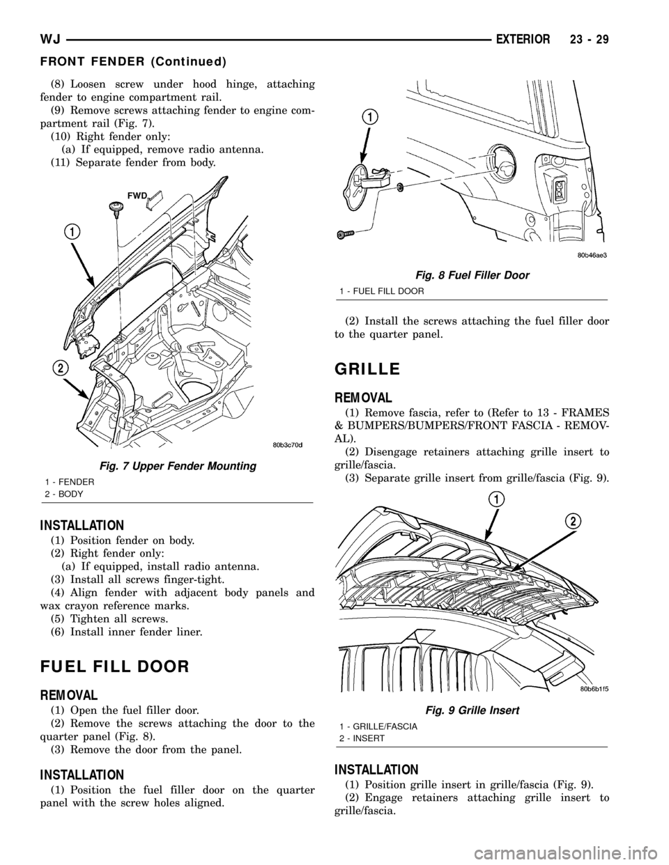
(8) Loosen screw under hood hinge, attaching
fender to engine compartment rail.
(9) Remove screws attaching fender to engine com-
partment rail (Fig. 7).
(10) Right fender only:
(a) If equipped, remove radio antenna.
(11) Separate fender from body.
INSTALLATION
(1) Position fender on body.
(2) Right fender only:
(a) If equipped, install radio antenna.
(3) Install all screws finger-tight.
(4) Align fender with adjacent body panels and
wax crayon reference marks.
(5) Tighten all screws.
(6) Install inner fender liner.
FUEL FILL DOOR
REMOVAL
(1) Open the fuel filler door.
(2) Remove the screws attaching the door to the
quarter panel (Fig. 8).
(3) Remove the door from the panel.
INSTALLATION
(1) Position the fuel filler door on the quarter
panel with the screw holes aligned.(2) Install the screws attaching the fuel filler door
to the quarter panel.
GRILLE
REMOVAL
(1) Remove fascia, refer to (Refer to 13 - FRAMES
& BUMPERS/BUMPERS/FRONT FASCIA - REMOV-
AL).
(2) Disengage retainers attaching grille insert to
grille/fascia.
(3) Separate grille insert from grille/fascia (Fig. 9).
INSTALLATION
(1) Position grille insert in grille/fascia (Fig. 9).
(2) Engage retainers attaching grille insert to
grille/fascia.
Fig. 7 Upper Fender Mounting
1 - FENDER
2 - BODY
Fig. 8 Fuel Filler Door
1 - FUEL FILL DOOR
Fig. 9 Grille Insert
1 - GRILLE/FASCIA
2 - INSERT
WJEXTERIOR 23 - 29
FRONT FENDER (Continued)
Page 1933 of 2199

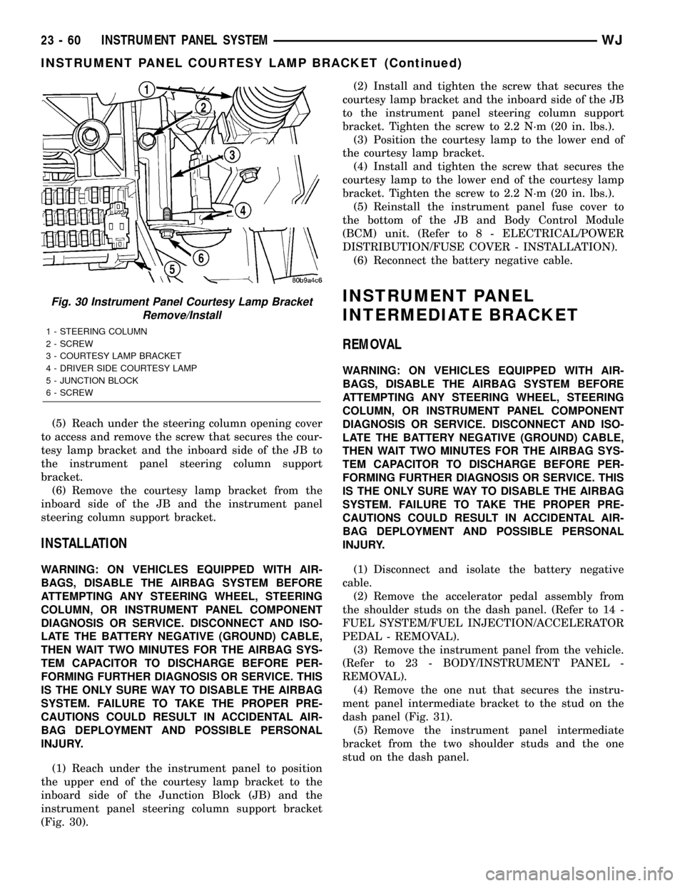
(5) Reach under the steering column opening cover
to access and remove the screw that secures the cour-
tesy lamp bracket and the inboard side of the JB to
the instrument panel steering column support
bracket.
(6) Remove the courtesy lamp bracket from the
inboard side of the JB and the instrument panel
steering column support bracket.
INSTALLATION
WARNING: ON VEHICLES EQUIPPED WITH AIR-
BAGS, DISABLE THE AIRBAG SYSTEM BEFORE
ATTEMPTING ANY STEERING WHEEL, STEERING
COLUMN, OR INSTRUMENT PANEL COMPONENT
DIAGNOSIS OR SERVICE. DISCONNECT AND ISO-
LATE THE BATTERY NEGATIVE (GROUND) CABLE,
THEN WAIT TWO MINUTES FOR THE AIRBAG SYS-
TEM CAPACITOR TO DISCHARGE BEFORE PER-
FORMING FURTHER DIAGNOSIS OR SERVICE. THIS
IS THE ONLY SURE WAY TO DISABLE THE AIRBAG
SYSTEM. FAILURE TO TAKE THE PROPER PRE-
CAUTIONS COULD RESULT IN ACCIDENTAL AIR-
BAG DEPLOYMENT AND POSSIBLE PERSONAL
INJURY.
(1) Reach under the instrument panel to position
the upper end of the courtesy lamp bracket to the
inboard side of the Junction Block (JB) and the
instrument panel steering column support bracket
(Fig. 30).(2) Install and tighten the screw that secures the
courtesy lamp bracket and the inboard side of the JB
to the instrument panel steering column support
bracket. Tighten the screw to 2.2 N´m (20 in. lbs.).
(3) Position the courtesy lamp to the lower end of
the courtesy lamp bracket.
(4) Install and tighten the screw that secures the
courtesy lamp to the lower end of the courtesy lamp
bracket. Tighten the screw to 2.2 N´m (20 in. lbs.).
(5) Reinstall the instrument panel fuse cover to
the bottom of the JB and Body Control Module
(BCM) unit. (Refer to 8 - ELECTRICAL/POWER
DISTRIBUTION/FUSE COVER - INSTALLATION).
(6) Reconnect the battery negative cable.
INSTRUMENT PANEL
INTERMEDIATE BRACKET
REMOVAL
WARNING: ON VEHICLES EQUIPPED WITH AIR-
BAGS, DISABLE THE AIRBAG SYSTEM BEFORE
ATTEMPTING ANY STEERING WHEEL, STEERING
COLUMN, OR INSTRUMENT PANEL COMPONENT
DIAGNOSIS OR SERVICE. DISCONNECT AND ISO-
LATE THE BATTERY NEGATIVE (GROUND) CABLE,
THEN WAIT TWO MINUTES FOR THE AIRBAG SYS-
TEM CAPACITOR TO DISCHARGE BEFORE PER-
FORMING FURTHER DIAGNOSIS OR SERVICE. THIS
IS THE ONLY SURE WAY TO DISABLE THE AIRBAG
SYSTEM. FAILURE TO TAKE THE PROPER PRE-
CAUTIONS COULD RESULT IN ACCIDENTAL AIR-
BAG DEPLOYMENT AND POSSIBLE PERSONAL
INJURY.
(1) Disconnect and isolate the battery negative
cable.
(2) Remove the accelerator pedal assembly from
the shoulder studs on the dash panel. (Refer to 14 -
FUEL SYSTEM/FUEL INJECTION/ACCELERATOR
PEDAL - REMOVAL).
(3) Remove the instrument panel from the vehicle.
(Refer to 23 - BODY/INSTRUMENT PANEL -
REMOVAL).
(4) Remove the one nut that secures the instru-
ment panel intermediate bracket to the stud on the
dash panel (Fig. 31).
(5) Remove the instrument panel intermediate
bracket from the two shoulder studs and the one
stud on the dash panel.
Fig. 30 Instrument Panel Courtesy Lamp Bracket
Remove/Install
1 - STEERING COLUMN
2 - SCREW
3 - COURTESY LAMP BRACKET
4 - DRIVER SIDE COURTESY LAMP
5 - JUNCTION BLOCK
6 - SCREW
23 - 60 INSTRUMENT PANEL SYSTEMWJ
INSTRUMENT PANEL COURTESY LAMP BRACKET (Continued)
Page 1934 of 2199

INSTALLATION
WARNING: ON VEHICLES EQUIPPED WITH AIR-
BAGS, DISABLE THE AIRBAG SYSTEM BEFORE
ATTEMPTING ANY STEERING WHEEL, STEERING
COLUMN, OR INSTRUMENT PANEL COMPONENT
DIAGNOSIS OR SERVICE. DISCONNECT AND ISO-
LATE THE BATTERY NEGATIVE (GROUND) CABLE,
THEN WAIT TWO MINUTES FOR THE AIRBAG SYS-
TEM CAPACITOR TO DISCHARGE BEFORE PER-
FORMING FURTHER DIAGNOSIS OR SERVICE. THIS
IS THE ONLY SURE WAY TO DISABLE THE AIRBAG
SYSTEM. FAILURE TO TAKE THE PROPER PRE-
CAUTIONS COULD RESULT IN ACCIDENTAL AIR-
BAG DEPLOYMENT AND POSSIBLE PERSONAL
INJURY.
(1) Position the instrument panel intermediate
bracket to the two shoulder studs and the one stud
on the dash panel (Fig. 31).
(2) Loosely install the one nut that secures the
intermediate bracket to the one stud on the dash
panel.
(3) Reinstall the instrument panel into the vehicle.
(Refer to 23 - BODY/INSTRUMENT PANEL -
INSTALLATION).
(4) Reinstall the accelerator pedal assembly onto
the shoulder studs on the dash panel. (Refer to 14 -FUEL SYSTEM/FUEL INJECTION/ACCELERATOR
PEDAL - INSTALLATION).
(5) Reconnect the battery negative cable.
INSTRUMENT PANEL LOWER
RIGHT CENTER BEZEL
REMOVAL
WARNING: ON VEHICLES EQUIPPED WITH AIR-
BAGS, DISABLE THE AIRBAG SYSTEM BEFORE
ATTEMPTING ANY STEERING WHEEL, STEERING
COLUMN, OR INSTRUMENT PANEL COMPONENT
DIAGNOSIS OR SERVICE. DISCONNECT AND ISO-
LATE THE BATTERY NEGATIVE (GROUND) CABLE,
THEN WAIT TWO MINUTES FOR THE AIRBAG SYS-
TEM CAPACITOR TO DISCHARGE BEFORE PER-
FORMING FURTHER DIAGNOSIS OR SERVICE. THIS
IS THE ONLY SURE WAY TO DISABLE THE AIRBAG
SYSTEM. FAILURE TO TAKE THE PROPER PRE-
CAUTIONS COULD RESULT IN ACCIDENTAL AIR-
BAG DEPLOYMENT AND POSSIBLE PERSONAL
INJURY.
(1) Disconnect and isolate the battery negative
cable.
(2) Unlatch and open the glove box.
(3) Remove the three screws that secure the lower
right center bezel to the instrument panel glove box
opening (Fig. 32).
(4) Pull the lower right center bezel straight back
from the instrument panel to disengage the two snap
clips that secure it to the receptacles in the instru-
ment panel top pad.
(5) Remove the lower right center bezel from the
instrument panel.
INSTALLATION
WARNING: ON VEHICLES EQUIPPED WITH AIR-
BAGS, DISABLE THE AIRBAG SYSTEM BEFORE
ATTEMPTING ANY STEERING WHEEL, STEERING
COLUMN, OR INSTRUMENT PANEL COMPONENT
DIAGNOSIS OR SERVICE. DISCONNECT AND ISO-
LATE THE BATTERY NEGATIVE (GROUND) CABLE,
THEN WAIT TWO MINUTES FOR THE AIRBAG SYS-
TEM CAPACITOR TO DISCHARGE BEFORE PER-
FORMING FURTHER DIAGNOSIS OR SERVICE. THIS
IS THE ONLY SURE WAY TO DISABLE THE AIRBAG
SYSTEM. FAILURE TO TAKE THE PROPER PRE-
CAUTIONS COULD RESULT IN ACCIDENTAL AIR-
BAG DEPLOYMENT AND POSSIBLE PERSONAL
INJURY.
(1) Be certain that the glove box catch bumper is
installed in the mounting hole nearest the inboard
Fig. 31 Instrument Panel Intermediate Bracket
Remove/Install
1 - STUD
2 - DASH PANEL
3 - NUT (2)
4 - INTERMEDIATE BRACKET
5 - NUT (2)
6 - ACCELERATOR PEDAL
7 - SHOULDER STUDS
WJINSTRUMENT PANEL SYSTEM 23 - 61
INSTRUMENT PANEL INTERMEDIATE BRACKET (Continued)
Page 1985 of 2199

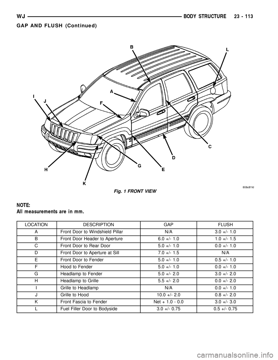
NOTE:
All measurements are in mm.
LOCATION DESCRIPTION GAP FLUSH
A Front Door to Windshield Pillar N/A 3.0 +/- 1.0
B Front Door Header to Aperture 6.0 +/- 1.0 1.0 +/- 1.5
C Front Door to Rear Door 5.0 +/- 1.0 0.0 +/- 1.0
D Front Door to Aperture at Sill 7.0 +/- 1.5 N/A
E Front Door to Fender 5.0 +/- 1.0 0.5 +/- 1.0
F Hood to Fender 5.0 +/- 1.0 0.0 +/- 1.0
G Headlamp to Fender 5.0 +/- 2.0 3.0 +/- 2.0
H Headlamp to Grille 5.5 +/- 2.0 0.0 +/- 2.0
I Grille to Headlamp N/A 0.0 +/- 1.0
J Grille to Hood 10.0 +/- 2.0 0.8 +/- 2.0
K Front Fascia to Fender Net + 1.0 - 0.0 3.0 +/- 3.0
L Fuel Filler Door to Bodyside 3.0 +/- 0.75 0.5 +/- 0.75
Fig. 1 FRONT VIEW
WJBODY STRUCTURE 23 - 113
GAP AND FLUSH (Continued)
Page 1991 of 2199

SEALER LOCATIONS
SPECIFICATIONS
SEALER LOCATIONS
INDEX
DESCRIPTION FIGURE
APPLICATION METHODS 6
COWL PLENUM AND DASH PANEL 7
DASH, COWL AND PLENUM 8
INNER FENDER AND COWL 9
LOWER PLENUM AND BAFFLE 10
A-PILLAR 11
COWL SIDE ATTACHMENT 12
BODYSIDE ATTACHMENT 13
BODYSIDE INNER AND OUTER TO COWL 14
FENDER ATTACHMENT 15
DOOR HINGE BOLT HOLES 16
A-PILLAR AND B-PILLAR HINGE AREA 17
B-PILLAR AND SILL 18
SILL AND B-PILLAR 19
BODYSIDE APERTURE AND REAR WHEELHOUSE 20
FUEL FILLER GUSSET 21
OUTER WHEELHOUSE FLANGE 22
LIFTGATE OPENING 23
INNER WHEELHOUSE FLANGE TO BODYSIDE APERTURE 24
WHEELHOUSE LOWER 25
REAR INNER CROSSMEMBER 26
ROOF TO BODY SIDE APERTURE 27
23 - 118 BODY STRUCTUREWJ