2002 JEEP GRAND CHEROKEE o2 location
[x] Cancel search: o2 locationPage 32 of 2199

LOWER BALL JOINT
REMOVAL
Ball stud service procedures below require removal
of the hub bearing and axle shaft. Removal and
installation of upper and lower ball studs require the
use of Tool Kit 6289.
(1) Position tools as shown to remove and install
ball stud (Fig. 6).
LOWER CONTROL ARM
DESCRIPTION
The lower suspension arms are hydroformed steel
and use voided oval bushings at one end of the arm.
OPERATION
The bushings provide isolation from the axle. The
arms mount to the unibody frame rail bracket and
the axle brackets. The arm and bushings provide
location and react to loads from the axle.
REMOVAL
(1) Raise the vehicle and support the front axle.
(2) Remove the lower suspension arm nut and bolt
from the axle bracket (Fig. 7).
(3) Remove the nut and bolt from the frame rail
bracket and remove the lower suspension arm (Fig.
7).
INSTALLATION
(1) Position the lower suspension arm in the axle
bracket and frame rail bracket.
NOTE: The end of the arm with the oval bushing
attaches to the axle bracket.
(2) Install the axle bracket bolt and nut finger
tight.
(3) Install the frame rail bracket bolt and nut fin-
ger tight.
(4) Remove support and lower the vehicle.
(5) With the vehicle on the ground tighten the
frame bracket bolt to 156 N´m (115 ft. lbs.). Tighten
the axle bracket nut to 163 N´m (120 ft. lbs.).
(6) Check the alignment if new parts were
installed.
Fig. 6 Lower
1 - SPECIAL TOOL 6289±12
2 - SPECIAL TOOL 6289±4
3 - SPECIAL TOOL 4212F
4 - SPECIAL TOOL 4212F5 - SPECIAL TOOL 6289±1
6 - SPECIAL TOOL 6289±3
WJFRONT 2 - 11
Page 35 of 2199

(6) Install the track bar to the axle bracket and
install the mounting bolt.
NOTE: It may be necessary to pry the axle assem-
bly over to install the track bar bolt.
(7) Remove the hydraulic jack from under the
vehicle.
(8) Tighten all suspension components to proper
torque.
(9) Install the wheel and tire assemblies.
(10) Remove support and lower vehicle.
STABILIZER BAR
DESCRIPTION
The bar extends across the front underside of the
chassis and is mounted to the frame rails. Links are
connected from the bar to the axle brackets. The sta-
bilizer bar and links are isolated by rubber bushings.
OPERATION
The stabilizer bar is used to control vehicle body
roll during turns. The spring steel bar helps to con-
trol the vehicle body in relationship to the suspen-
sion.
REMOVAL
(1) Raise and support the vehicle.
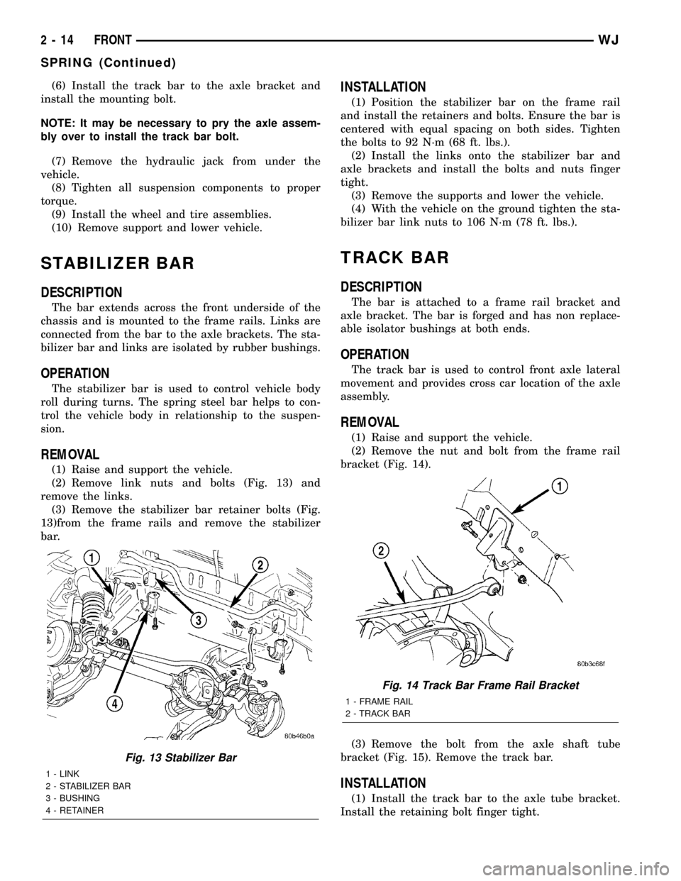
(2) Remove link nuts and bolts (Fig. 13) and
remove the links.
(3) Remove the stabilizer bar retainer bolts (Fig.
13)from the frame rails and remove the stabilizer
bar.
INSTALLATION
(1) Position the stabilizer bar on the frame rail
and install the retainers and bolts. Ensure the bar is
centered with equal spacing on both sides. Tighten
the bolts to 92 N´m (68 ft. lbs.).
(2) Install the links onto the stabilizer bar and
axle brackets and install the bolts and nuts finger
tight.
(3) Remove the supports and lower the vehicle.
(4) With the vehicle on the ground tighten the sta-
bilizer bar link nuts to 106 N´m (78 ft. lbs.).
TRACK BAR
DESCRIPTION
The bar is attached to a frame rail bracket and
axle bracket. The bar is forged and has non replace-
able isolator bushings at both ends.
OPERATION
The track bar is used to control front axle lateral
movement and provides cross car location of the axle
assembly.
REMOVAL
(1) Raise and support the vehicle.
(2) Remove the nut and bolt from the frame rail
bracket (Fig. 14).
(3) Remove the bolt from the axle shaft tube
bracket (Fig. 15). Remove the track bar.
INSTALLATION
(1) Install the track bar to the axle tube bracket.
Install the retaining bolt finger tight.
Fig. 13 Stabilizer Bar
1 - LINK
2 - STABILIZER BAR
3 - BUSHING
4 - RETAINER
Fig. 14 Track Bar Frame Rail Bracket
1 - FRAME RAIL
2 - TRACK BAR
2 - 14 FRONTWJ
SPRING (Continued)
Page 37 of 2199

UPPER CONTROL ARM
DESCRIPTION
The upper suspension arms are hydroformed steel
and use rubber bushings at each end of the arm.
OPERATION
The arms mount to the unibody frame rail bracket
and the axle brackets. The arm and bushings provide
location and react to loads from the axle. The bush-
ings provide isolation from the axle.
REMOVAL
(1) Raise vehicle and support the axle.
(2) Remove the upper suspension arm mounting
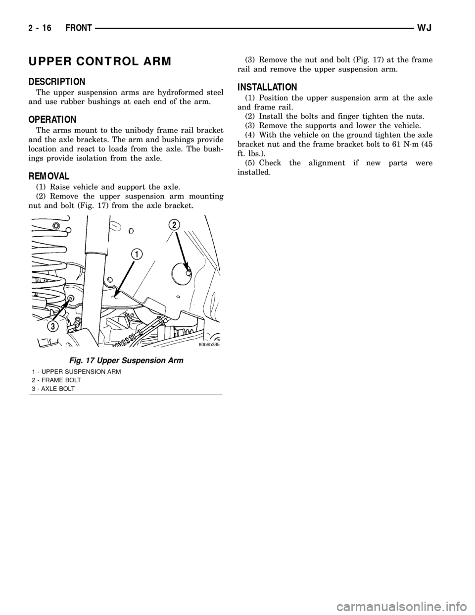
nut and bolt (Fig. 17) from the axle bracket.(3) Remove the nut and bolt (Fig. 17) at the frame
rail and remove the upper suspension arm.
INSTALLATION
(1) Position the upper suspension arm at the axle
and frame rail.
(2) Install the bolts and finger tighten the nuts.
(3) Remove the supports and lower the vehicle.
(4) With the vehicle on the ground tighten the axle
bracket nut and the frame bracket bolt to 61 N´m (45
ft. lbs.).
(5) Check the alignment if new parts were
installed.
Fig. 17 Upper Suspension Arm
1 - UPPER SUSPENSION ARM
2 - FRAME BOLT
3 - AXLE BOLT
2 - 16 FRONTWJ
Page 40 of 2199

SPECIAL TOOLS
REAR SUSPENSION
LOWER CONTROL ARM
DESCRIPTION
The lower suspension arms are hydroformed steel
and use voided oval bushings at each end of the arm.
OPERATION
The bushings provide isolation from the axle. The
arms mount to the unibody frame rail bracket and
the axle brackets. The arm and bushings provide
location and react to loads.
REMOVAL
(1) Raise the vehicle and support the rear axle.
(2) Remove the lower suspension arm nut and bolt
from the axle bracket (Fig. 2).
(3) Remove the nut and bolt (Fig. 2) from the
frame rail and remove the lower suspension arm.
INSTALLATION
(1) Position the lower suspension arm in the axle
bracket and frame rail bracket.
NOTE: The end of the arm with the oval bushing
attaches to the axle bracket.
(2) Install the axle bracket bolt and nut finger
tight.
(3) Install the frame rail bracket bolt and nut fin-
ger tight.
(4) Remove the supports and lower the vehicle.
(5) With the vehicle on the ground tighten the nut
at the frame to 156 N´m (115 ft. lbs.). Tighten the
nut at the axle bracket to 163 N´m (120 ft. lbs.).
SHOCK
DESCRIPTION
The top of the shock absorbers are bolted to the
body. The bottom of the shocks are bolted to the axle
brackets. The standard shocks have conventional
twin tube construction and are low pressure gas
charged. Gas charging prevents cavitation during
rough road operation. Up-Country shocks are mono
tube design and are high pressure gas charged.
OPERATION
The shock absorbers dampen jounce and rebound
motion of the vehicle over various road conditions
and limit suspension rebound travel.
REMOVAL
(1) Raise and support the vehicle. Position a
hydraulic jack under the axle to support the axle.
CAUTION: Do not allow the axle to hang from the
upper suspension arm ball joint.
(2) Remove the upper nut and bolt from the frame
bracket (Fig. 3).
(3) Remove the lower nut and bolt from the axle
bracket. Remove the shock absorber.
INSTALLATION
(1) Install the shock absorber in the frame bracket
and install the bolt and nut.
(2) Install the shock absorber in the axle bracket
and install the bolt and nut.
(3) Tighten the upper mounting nuts to 108 N´m
(80 ft. lbs.). Tighten the lower mounting nuts to 115
N´m (85 ft. lbs.).
(4) Remove the supports and lower the vehicle.
Remover 8278
Fig. 2 Lower Suspension Arm
1 - LOWER SUSPENSION ARM
2 - AXLE BRACKET
3 - FRAME BRACKET
WJREAR 2 - 19
REAR (Continued)
Page 42 of 2199

STABILIZER BAR
DESCRIPTION
The stabilizer bar extends across the back side of
the rear axle. Links are connected between the bar
and frame rail brackets. The stabilizer bar and links
are isolated by rubber bushings.
OPERATION
The stabilizer bar is used to control vehicle body
roll, during turns. The bar helps control the vehicle
body in relationship to the suspension.
REMOVAL
(1) Raise and support the vehicle.
(2) Remove the stabilizer bar links from stabilizer
bar and frame mount. (Fig. 7).
(3) Remove the stabilizer bar retainer bolts.
(4) Remove the stabilizer bar.
INSTALLATION
(1) Position the stabilizer bar on the axle and
install the retainers and bolts. Ensure the bar is cen-
tered with equal spacing on both sides. Tighten the
bolts to 54 N´m (40 ft. lbs.).
(2) Install the links to the stabilizer bar and frame
brackets.
(3) Tighten the nuts at the stabilizer bar to 54
N´m (40 ft. lbs.).
(4) Tighten the nuts at the frame brackets to 92
N´m (68 ft. lbs.).
(5) Remove support and lower the vehicle.
UPPER BALL JOINT
DESCRIPTION - UPPER SUSPENSION ARM,
BUSHINGS, AND BALL JOINT
The suspension arm uses vertical spool bushings to
isolate road noise. The suspension arm is bolted
through bushings to cage nuts in the body and a ball
joint plate to the top of the differential housing.
OPERATION - UPPER SUSPENSION ARM,
BUSHINGS, AND BALL JOINT
The upper suspension arm provides fore/aft and
lateral location of the rear axle. The suspension arm
travel is limited through the use of jounce bumpers
in compression and shock absorbers in rebound.
REMOVAL
(1) Raise and support the vehicle.
(2) Support the rear axle with a hydraulic jack.
(3) Remove the ball joint nut from the top of the
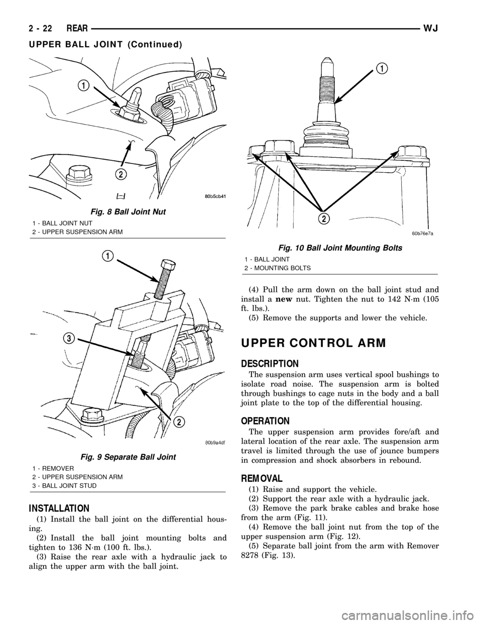
upper suspension arm (Fig. 8).
(4) Separate ball joint from the arm with Remover
8278 (Fig. 9).
NOTE: It may be necessary to strike the upper con-
trol arm with a hammer to separate the ball joint
from the arm.
(5) Remove the ball joint mounting bolts (Fig.
10)from the differential housing.
(6) Remove the ball joint from the differential
housing.
Fig. 6 Isolator Spring Locator - Typical
1 - LOWER ISOLATOR
2 - SPRING LOCATOR
3 - COIL SPRING
Fig. 7 Rear Stabilizer Bar
1 - LINK
2 - RETAINER
3 - BUSHING
4 - STABILIZER BAR
WJREAR 2 - 21
SPRING (Continued)
Page 43 of 2199

INSTALLATION
(1) Install the ball joint on the differential hous-
ing.
(2) Install the ball joint mounting bolts and
tighten to 136 N´m (100 ft. lbs.).
(3) Raise the rear axle with a hydraulic jack to
align the upper arm with the ball joint.(4) Pull the arm down on the ball joint stud and
install anewnut. Tighten the nut to 142 N´m (105
ft. lbs.).
(5) Remove the supports and lower the vehicle.
UPPER CONTROL ARM
DESCRIPTION
The suspension arm uses vertical spool bushings to
isolate road noise. The suspension arm is bolted
through bushings to cage nuts in the body and a ball
joint plate to the top of the differential housing.
OPERATION
The upper suspension arm provides fore/aft and
lateral location of the rear axle. The suspension arm
travel is limited through the use of jounce bumpers
in compression and shock absorbers in rebound.
REMOVAL
(1) Raise and support the vehicle.
(2) Support the rear axle with a hydraulic jack.
(3) Remove the park brake cables and brake hose
from the arm (Fig. 11).
(4) Remove the ball joint nut from the top of the
upper suspension arm (Fig. 12).
(5) Separate ball joint from the arm with Remover
8278 (Fig. 13).
Fig. 8 Ball Joint Nut
1 - BALL JOINT NUT
2 - UPPER SUSPENSION ARM
Fig. 9 Separate Ball Joint
1 - REMOVER
2 - UPPER SUSPENSION ARM
3 - BALL JOINT STUD
Fig. 10 Ball Joint Mounting Bolts
1 - BALL JOINT
2 - MOUNTING BOLTS
2 - 22 REARWJ
UPPER BALL JOINT (Continued)
Page 66 of 2199

INSTALLATION
CAUTION: The weight of the vehicle must be sup-
ported by the springs before suspension arms and
track bar fasteners can be tightened. If springs are
not at their normal ride position, ride height and
handling could be affected.
(1) Install the springs and retainer clips. Tighten
the retainer bolts to 21 N´m (16 ft. lbs.).
(2) Support the axle on a lifting device and posi-
tion axle under the vehicle.
(3) Raise the axle and align it with the spring
pads.
(4) Position the upper and lower suspension arms
in the axle brackets. Loosely install bolts and nuts to
hold suspension arms to the axle brackets.
(5) Install vent hose to the axle shaft tube.
(6) Install track bar in the axle bracket and install
the bolt loosely.
(7) Install shock absorbers and tighten the bolts to
23 N´m (17 ft. lbs.).
(8) Install stabilizer bar links to the axle brackets
and tighten the nuts to 95 N´m (70 ft. lbs.).
(9) Install drag link and tie rod to the steering
knuckles.
(10) Install steering damper to the axle bracket
and tighten the nut to 75 N´m (55 ft. lbs.).
(11) Install the brake rotors (Refer to 5 - BRAKES/
HYDRAULIC/MECHANICAL/ROTORS - INSTALLA-
TION) and calipers.
(12) Connect the wheel speed sensor wiring har-
ness to the vehicle wiring harness.
(13) Align the previously made marks on the pro-
peller shaft and the yoke/pinion flange.
(14) Install propeller shaft to pinion flange bolts ,
if equipped.
(15) Install propeller shaft to yoke straps and
bolts, if equipped.
(16) Check and fill axle lubricant.
(17) Install the wheel and tire assemblies.
(18) Remove the lifting device from the axle and
lower the vehicle.
(19) Tighten the upper suspension arm nuts to 75
N´m (55 ft. lbs.). Tighten the lower suspension arm
nuts to 115 N´m (85 ft. lbs.).
(20) Tighten the track bar bolt at the axle bracket
to 100 N´m (74 ft. lbs.).
(21) Check the front wheel alignment.
ADJUSTMENTS
Ring and pinion gears are supplied as matched
sets only. The identifying numbers for the ring and
pinion gear are etched onto each gear (Fig. 3). A plus
(+) number, minus (±) number or zero (0) is etched
into the face of the pinion gear. This number is theamount (in thousandths of an inch) the depth varies
from the standard depth setting of a pinion etched
with a (0). The standard setting from the center line
of the ring gear to the back face of the pinion is 92.1
mm (3.625 in.). The standard depth provides the best
gear tooth contact pattern. Refer to Backlash and
Contact Pattern Analysis paragraph in this section
for additional information.
Compensation for pinion depth variance is
achieved with a select shim/oil slinger. The shims are
placed between the rear pinion bearing and the pin-
ion gear head (Fig. 4).
Fig. 3 PINION GEAR ID NUMBERS
1 - PRODUCTION NUMBERS
2 - DRIVE PINION GEAR DEPTH VARIANCE
3 - GEAR MATCHING NUMBER
Fig. 4 ADJUSTMENT SHIM LOCATIONS
1 - PINION DEPTH SHIM/OIL SLINGER
2 - DIFFERENTIAL BEARING SHIM
3 - RING GEAR
4 - DIFFERENTIAL BEARING SHIM
5 - COLLAPSIBLE SPACER
WJFRONT AXLE - 186FBI 3 - 21
FRONT AXLE - 186FBI (Continued)
Page 69 of 2199

DIFFERENTIAL
Differential side bearing preload and gear backlash
is achieved by selective shims positioned behind the
differential side bearing cones. The proper shim
thickness can be determined using slip-fit Dummy
Bearings D-348 in place of the differential side bear-
ings and a Dial Indicator C-3339. Before proceeding
with the differential bearing preload and gear back-
lash measurements, measure the pinion gear depth
and prepare the pinion for installation. Establishing
proper pinion gear depth is essential to establishing
gear backlash and tooth contact patterns. After the
overall shim thickness to take up differential side
play is measured, the pinion is installed, and the
gear backlash shim thickness is measured. The over-
all shim thickness is the total of the dial indicator
reading and the preload specification added together.
The gear backlash measurement determines the
thickness of the shim used on the ring gear side of
the differential case. Subtract the gear backlash shim
thickness from the total overall shim thickness and
select that amount for the pinion gear side of the dif-
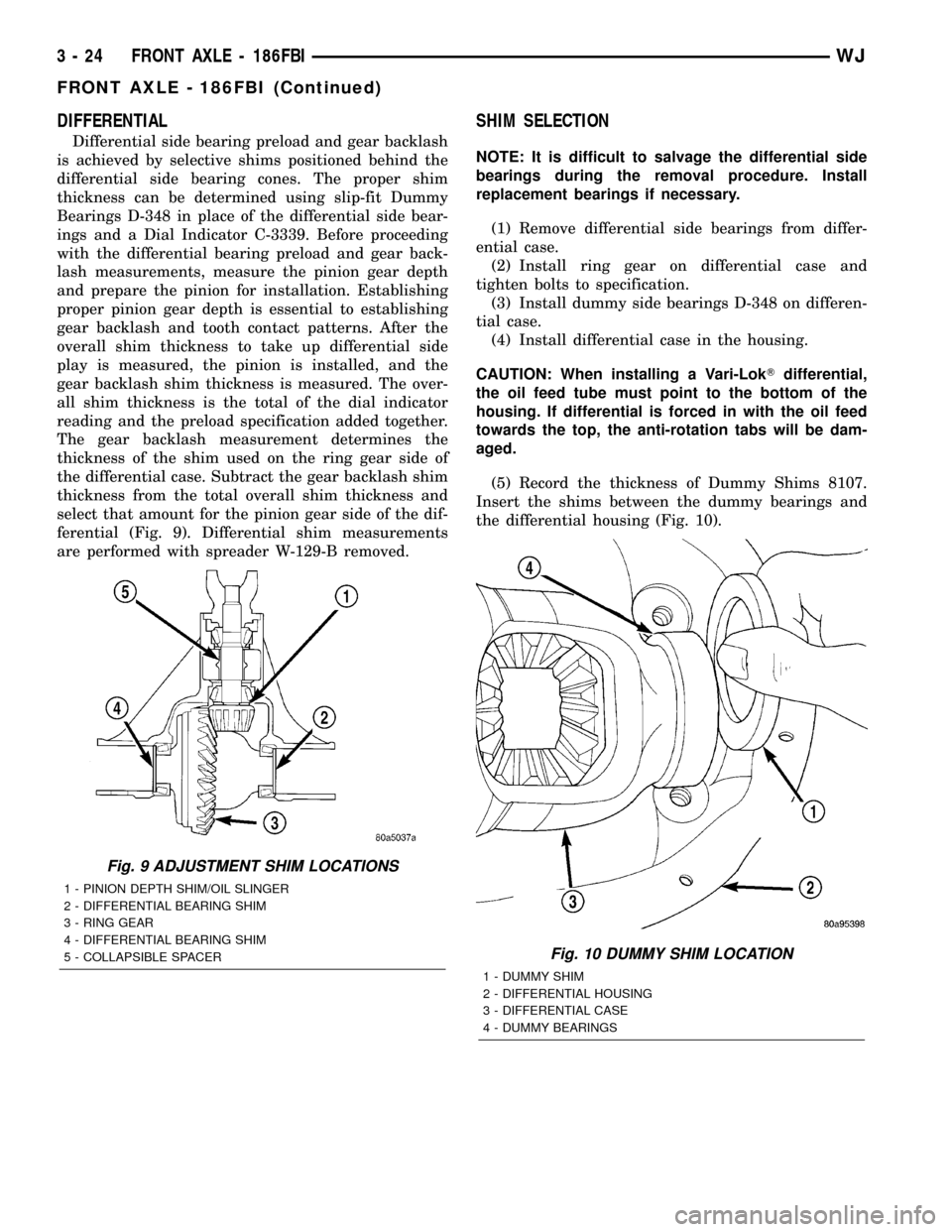
ferential (Fig. 9). Differential shim measurements
are performed with spreader W-129-B removed.
SHIM SELECTION
NOTE: It is difficult to salvage the differential side
bearings during the removal procedure. Install
replacement bearings if necessary.
(1) Remove differential side bearings from differ-
ential case.
(2) Install ring gear on differential case and
tighten bolts to specification.
(3) Install dummy side bearings D-348 on differen-
tial case.
(4) Install differential case in the housing.
CAUTION: When installing a Vari-LokTdifferential,
the oil feed tube must point to the bottom of the
housing. If differential is forced in with the oil feed
towards the top, the anti-rotation tabs will be dam-
aged.
(5) Record the thickness of Dummy Shims 8107.
Insert the shims between the dummy bearings and
the differential housing (Fig. 10).
Fig. 9 ADJUSTMENT SHIM LOCATIONS
1 - PINION DEPTH SHIM/OIL SLINGER
2 - DIFFERENTIAL BEARING SHIM
3 - RING GEAR
4 - DIFFERENTIAL BEARING SHIM
5 - COLLAPSIBLE SPACER
Fig. 10 DUMMY SHIM LOCATION
1 - DUMMY SHIM
2 - DIFFERENTIAL HOUSING
3 - DIFFERENTIAL CASE
4 - DUMMY BEARINGS
3 - 24 FRONT AXLE - 186FBIWJ
FRONT AXLE - 186FBI (Continued)