2002 JEEP GRAND CHEROKEE left turn
[x] Cancel search: left turnPage 1874 of 2199

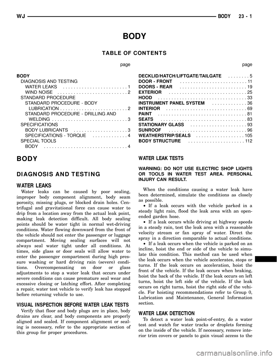
BODY
TABLE OF CONTENTS
page page
BODY
DIAGNOSIS AND TESTING
WATER LEAKS........................1
WIND NOISE..........................2
STANDARD PROCEDURE
STANDARD PROCEDURE - BODY
LUBRICATION.........................2
STANDARD PROCEDURE - DRILLING AND
WELDING............................3
SPECIFICATIONS
BODY LUBRICANTS....................3
SPECIFICATIONS - TORQUE.............4
SPECIAL TOOLS
BODY...............................4DECKLID/HATCH/LIFTGATE/TAILGATE........5
DOOR - FRONT.........................11
DOORS - REAR.........................19
EXTERIOR.............................25
HOOD.................................33
INSTRUMENT PANEL SYSTEM.............36
INTERIOR..............................69
PAINT.................................81
SEATS................................83
STATIONARY GLASS.....................93
SUNROOF.............................96
WEATHERSTRIP/SEALS..................105
BODY STRUCTURE.....................112
BODY
DIAGNOSIS AND TESTING
WATER LEAKS
Water leaks can be caused by poor sealing,
improper body component alignment, body seam
porosity, missing plugs, or blocked drain holes. Cen-
trifugal and gravitational force can cause water to
drip from a location away from the actual leak point,
making leak detection difficult. All body sealing
points should be water tight in normal wet-driving
conditions. Water flowing downward from the front of
the vehicle should not enter the passenger or luggage
compartment. Moving sealing surfaces will not
always seal water tight under all conditions. At
times, side glass or door seals will allow water to
enter the passenger compartment during high pres-
sure washing or hard driving rain (severe) condi-
tions. Overcompensating on door or glass
adjustments to stop a water leak that occurs under
severe conditions can cause premature seal wear and
excessive closing or latching effort. After completing
a repair, water test vehicle to verify leak has stopped
before returning vehicle to use.
VISUAL INSPECTION BEFORE WATER LEAK TESTS
Verify that floor and body plugs are in place, body
drains are clear, and body components are properly
aligned and sealed. If component alignment or seal-
ing is necessary, refer to the appropriate section of
this group for proper procedures.
WATER LEAK TESTS
WARNING: DO NOT USE ELECTRIC SHOP LIGHTS
OR TOOLS IN WATER TEST AREA. PERSONAL
INJURY CAN RESULT.
When the conditions causing a water leak have
been determined, simulate the conditions as closely
as possible.
²If a leak occurs with the vehicle parked in a
steady light rain, flood the leak area with an open-
ended garden hose.
²If a leak occurs while driving at highway speeds
in a steady rain, test the leak area with a reasonable
velocity stream or fan spray of water. Direct the
spray in a direction comparable to actual conditions.
²If a leak occurs when the vehicle is parked on an
incline, hoist the end or side of the vehicle to simu-
late this condition. This method can be used when
the leak occurs when the vehicle accelerates, stops or
turns. If the leak occurs on acceleration, hoist the
front of the vehicle. If the leak occurs when braking,
hoist the back of the vehicle. If the leak occurs on left
turns, hoist the left side of the vehicle. If the leak
occurs on right turns, hoist the right side of the vehi-
cle. For hoisting recommendations refer to Group 0,
Lubrication and Maintenance, General Information
section.
WATER LEAK DETECTION
To detect a water leak point-of-entry, do a water
test and watch for water tracks or droplets forming
on the inside of the vehicle. If necessary, remove inte-
rior trim covers or panels to gain visual access to the
WJBODY 23 - 1
Page 1910 of 2199

INSTRUMENT PANEL SYSTEM
REMOVAL
WARNING: ON VEHICLES EQUIPPED WITH AIR-
BAGS, DISABLE THE AIRBAG SYSTEM BEFORE
ATTEMPTING ANY STEERING WHEEL, STEERING
COLUMN, OR INSTRUMENT PANEL COMPONENT
DIAGNOSIS OR SERVICE. DISCONNECT AND ISO-
LATE THE BATTERY NEGATIVE (GROUND) CABLE,
THEN WAIT TWO MINUTES FOR THE AIRBAG SYS-
TEM CAPACITOR TO DISCHARGE BEFORE PER-
FORMING FURTHER DIAGNOSIS OR SERVICE. THIS
IS THE ONLY SURE WAY TO DISABLE THE AIRBAG
SYSTEM. FAILURE TO TAKE THE PROPER PRE-
CAUTIONS COULD RESULT IN ACCIDENTAL AIR-
BAG DEPLOYMENT AND POSSIBLE PERSONAL
INJURY.
NOTE: Before starting this procedure, be certain to
turn the steering wheel until the front wheels are in
the straight-ahead position.
(1) Disconnect and isolate the battery negative
cable.
(2) Remove the trim from the right and left A-pil-
lars. (Refer to 23 - BODY/INTERIOR/A-PILLAR
TRIM - REMOVAL).(3) Remove the top cover from the instrument
panel. (Refer to 23 - BODY/INSTRUMENT PANEL/
INSTRUMENT PANEL TOP COVER - REMOVAL).
(4) Remove the four nuts that secure the instru-
ment panel to the studs on the dash panel near the
windshield fence line (Fig. 1).
(5) Remove the scuff plates from the right and left
front door sills. (Refer to 23 - BODY/INTERIOR/
DOOR SILL SCUFF PLATE - REMOVAL).
(6) Remove the trim panels from the right and left
inner cowl sides. (Refer to 23 - BODY/INTERIOR/
COWL TRIM - REMOVAL).
(7) Remove the console from the floor panel trans-
mission tunnel. (Refer to 23 - BODY/INTERIOR/
FLOOR CONSOLE - REMOVAL).
(8) Remove the fuse cover from the Junction Block
(JB). (Refer to 8 - ELECTRICAL/POWER DISTRIBU-
TION/FUSE COVER - REMOVAL).
(9) Remove the cluster bezel from the instrument
panel. (Refer to 23 - BODY/INSTRUMENT PANEL/
CLUSTER BEZEL - REMOVAL).
(10) Remove the steering column opening cover
from the instrument panel. (Refer to 23 - BODY/IN-
STRUMENT PANEL/STEERING COLUMN OPEN-
ING COVER - REMOVAL).
(11) Remove the steering column bracket from the
instrument panel steering column support bracket.
(Refer to 23 - BODY/INSTRUMENT PANEL/IP
STEERING COLUMN BRACKET - REMOVAL).
Fig. 1 Instrument Panel to Dash Panel Mounting
1 - STUD (4)
2 - NUT (4)3 - INSTRUMENT PANEL
4 - DASH PANEL
WJINSTRUMENT PANEL SYSTEM 23 - 37
Page 1911 of 2199

(12) Remove the screw that secures the lower tilt-
ing steering column shroud to the steering column
multi-function switch mounting housing (Fig. 2).
(13) Unsnap the two halves of the tilting steering
column shroud from each other and remove both
halves from the steering column.
(14) Disconnect the instrument panel wire harness
connectors from the following steering column compo-
nents (Fig. 3):
²the two lower clockspring connector receptacles
²the left multi-function switch connector recepta-
cle
²the right multi-function switch connector recep-
tacle
²the two ignition switch connector receptacles
²the shifter interlock solenoid connector recepta-
cle
²if the vehicle is so equipped, the Sentry Key
Immobilizer Module (SKIM) connector receptacle.
(15) Turn the ignition switch to the On position,
then release and remove the shifter interlock cable
connector from the ignition lock housing receptacle.
(16) Turn the ignition switch back to the Lock
position to prevent steering wheel rotation and theloss of clockspring centering following steering col-
umn removal.
(17) Remove the bolt that secures the coupler to
the lower steering column shaft (Fig. 4).
Fig. 2 Steering Column Shrouds Remove/Install
1 - UPPER TILTING COLUMN SHROUD
2 - FIXED COLUMN SHROUD
3 - LOWER TILTING COLUMN SHROUD
4 - SCREW
Fig. 3 Steering Column Connections
1 - LEFT MULTIFUNCTION SWITCH CONNECTOR
2 - LOWER CLOCKSPRING CONNECTORS
3 - RIGHT MULTIFUNCTION SWITCH CONNECTOR
4 - SHIFTER INTERLOCK CABLE CONNECTOR
5 - SHIFTER INTERLOCK SOLENOID CONNECTOR
6 - IGNITION SWITCH CONNECTOR RECEPTACLES
7 - SKIM CONNECTOR
Fig. 4 Steering Column Mounting
1 - COLUMN MOUNTING NUTS
2 - COUPLER BOLT
23 - 38 INSTRUMENT PANEL SYSTEMWJ
INSTRUMENT PANEL SYSTEM (Continued)
Page 1917 of 2199

(23) Reconnect the instrument panel wire harness
connectors to the following floor panel transmission
tunnel components:
²the Airbag Control Module (ACM) connector
receptacle
²the park brake switch terminal
²the transmission shifter connector receptacle.
(24) Reconnect the left and right body wire har-
ness connectors, the Ignition Off Draw (IOD) wire
harness connector and the fused B(+) wire harness
connector to the connector receptacles of the Junction
Block (JB) and tighten the connector screws (Fig. 5).
Tighten the screws to 4 N´m (36 in. lbs.).
(25) Engage the lower steering column shaft with
the steering shaft coupler and position the steering
column to the mounting studs on the instrument
panel steering column support bracket (Fig. 4).
(26) Install and tighten the four nuts that secure
the steering column to the studs on the instrument
panel steering column support bracket. Tighten the
nuts to 11.8 N´m (105 in. lbs.).
(27) Install and tighten the bolt that secures the
coupler to the lower steering column shaft. Tighten
the bolt to 49 N´m (36 ft. lbs.).
(28) Turn the ignition switch to the On position,
then install the shifter interlock cable connector into
the ignition lock housing receptacle.
(29) Reconnect the instrument panel wire harness
connectors to the following steering column compo-
nents (Fig. 3):
²the two lower clockspring connector receptacles
²the left multi-function switch connector recepta-
cle
²the right multi-function switch connector recep-
tacle
²the two ignition switch connector receptacles
²the shifter interlock solenoid connector recepta-
cle
²if the vehicle is so equipped, the Sentry Key
Immobilizer Module (SKIM) connector receptacle.
(30) Position the lower tilting steering column
shroud to the steering column multi-function switchmounting housing, then install and tighten the screw
that secures the shroud to the housing (Fig. 2).
Tighten the screw to 1.9 N´m (17 in. lbs.).
(31) Position the upper tilting steering column
shroud over the steering column. Align the upper and
lower shrouds with each other and snap the two
halves together.
(32) Reinstall the steering column bracket onto the
instrument panel steering column support bracket.
(Refer to 23 - BODY/INSTRUMENT PANEL/IP
STEERING COLUMN BRACKET - INSTALLA-
TION).
(33) Reinstall the steering column opening cover
onto the instrument panel. (Refer to 23 - BODY/IN-
STRUMENT PANEL/STEERING COLUMN OPEN-
ING COVER - INSTALLATION).
(34) Reinstall the cluster bezel onto the instru-
ment panel. (Refer to 23 - BODY/INSTRUMENT
PANEL/CLUSTER BEZEL - INSTALLATION).
(35) Reinstall the fuse cover onto the Junction
Block (JB). (Refer to 8 - ELECTRICAL/POWER DIS-
TRIBUTION/FUSE COVER - INSTALLATION).
(36) Reinstall the console onto the floor panel
transmission tunnel. (Refer to 23 - BODY/INTERI-
OR/FLOOR CONSOLE - INSTALLATION).
(37) Reinstall the trim panels onto the right and
left inner cowl sides. (Refer to 23 - BODY/INTERI-
OR/COWL TRIM - INSTALLATION).
(38) Reinstall the scuff plates onto the right and
left front door sills. (Refer to 23 - BODY/INTERIOR/
DOOR SILL SCUFF PLATE - INSTALLATION).
(39) Reinstall the top cover onto the instrument
panel. (Refer to 23 - BODY/INSTRUMENT PANEL/
INSTRUMENT PANEL TOP COVER - INSTALLA-
TION).
(40) Reinstall the trim onto the right and left
A-pillars. (Refer to 23 - BODY/INTERIOR/A-PILLAR
TRIM - INSTALLATION).
(41) Reconnect the battery negative cable.
23 - 44 INSTRUMENT PANEL SYSTEMWJ
INSTRUMENT PANEL SYSTEM (Continued)
Page 1962 of 2199

REAR HEADREST SLEEVE
REMOVAL
(1) Remove seat back (Refer to 23 - BODY/SEATS/
REAR SEAT BACK - REMOVAL).
(2) Remove head rest (Refer to 23 - BODY/SEATS/
REAR HEADREST - REMOVAL).
(3) Remove head rest caps.
(4) Remove seat back cover (Refer to 23 - BODY/
SEATS/REAR SEAT BACK COVER - REMOVAL).
(5) Rotate head rest sleeve 1/4 turn counter-clock-
wise to release retaining tab.
(6) Pull sleeve from seat back frame.
INSTALLATION
(1) Position sleeve in seat back frame.
(2) Rotate head rest sleeve 1/4 turn clockwise to
engage retaining tab.
(3) Install seat back cover (Refer to 23 - BODY/
SEATS/REAR SEAT BACK COVER - INSTALLA-
TION).
(4) Install head rest caps.
NOTE: The head rest cap with the taller button is
always on the inboard side of the seat back.
(5) Install the head rest (Refer to 23 - BODY/
SEATS/REAR HEADREST - INSTALLATION).
NOTE: The folding head rest release knob is always
on the outboard side.
(6) Install the seat back (Refer to 23 - BODY/
SEATS/REAR SEAT BACK - INSTALLATION).
REAR SEAT BACK
REMOVAL
(1) Move rear seat cushions to forward cargo posi-
tion.
(2) Remove bolts attaching seatback side support
bracket to floor pan (right side) (Fig. 11).
(3) Tilt seatback forward, and slide it outboard to
detach it from pin on center pivot bracket.
(4) Remove right side (60%) seatback from vehicle.
(5) Remove bolts attaching seatback side support
bracket and center pivot bracket to floor pan (left
side).
(6) Remove left side (40%) seatback from vehicle.
INSTALLATION
(1) Position left side (40%) seatback in vehicle.
(2) Position left side support bracket and center
pivot bracket with bolt holes aligned and install
bolts. Tighten bolts to 28 N´m (20 ft. lbs.) torque.
(3) Position right side (60%) seatback in vehicle.
(4) Install seatback onto center pivot bracket pin.
Ensure seat back is properly engaged on the center
pivot pin.
(5) Position right side support bracket with bolt
holes aligned and install bolts. Tighten bolts to 28
N´m (20 ft. lbs.) torque.
(6) Return seat cushions to seating position.
Fig. 11 Rear Seat Back
1 - SEAT BACK
2 - FLOOR PAN
3 - CENTER PIVOT BRACKET
4 - SIDE SUPPORT BRACKET
WJSEATS 23 - 89
Page 2095 of 2199

Both the manual A/C Heater control panel and the
AZC control panel are serviced only as complete
units and cannot be repaired. If faulty or damaged,
the entire control panel unit must be replaced.
DIAGNOSIS AND TESTING - AUTOMATIC ZONE
CONTROL SYSTEM
The Automatic Zone Control (AZC) control module
has a system self-diagnostic mode which continuously
monitors various parameters during normal system
operation. If a system fault is detected, a current and
historical fault is recorded. When the current fault is
cleared, the historical fault remains until reset (man-
ually or automatically). Both the current and histor-
ical fault codes can be accessed through either the
front panel, or over the Programmable Communica-
tions Interface (PCI) bus using a DRBIIItscan tool,
and the appropriate diagnostic information.
The AZC control module is capable of three differ-
ent types of self-diagnostic tests, as follows:
²Fault Code Tests
²Input Circuit Tests
²Output Circuit/Actuator Tests
The information that follows describes:
²How to read the self-diagnostic display
²How to enter the AZC control module self-diag-
nostic test mode
²How to select the self-diagnostic test types
²How to perform the different tests
ENTERING THE AZC SELF-DIAGNOSTIC MODE
To enter the AZC self-diagnostic mode, perform the
following:
(1) Depress the a/c and recirc buttons at the same
time and hold. Rotate the left temperature control
knob clockwise (CW) one detent.
(2) If you continue to keep the a/c and recirc but-
tons depressed, the AZC control module will perform
a Segment Test of the Vacuum Fluorescent (VF) dis-
play. In the Segment Test you should see all of the
display segments illuminate as long as both buttons
are held. If a display segment fails to illuminate, the
vacuum fluorescent display is faulty and the a/c
heater control must be replaced.
(3) After viewing the Segment Test, release the
A/C and Recirc buttons and the display will clear
momentarily.Ifa0isdisplayed, then no faults
are set in the system.Should there be any faults,
either9current9or9historical9, all fault codes will be
displayed in ascending numerical sequence (note no
effort is made to display fault codes in chronological
order). Each fault code is displayed for one second
before the next code is displayed. Once all fault codes
have been displayed, the system will then repeat the
fault code numbers. This will continue until the left
side set temperature control is moved at least onedetent position in the CW direction or the ignition is
turned9OFF9.
FAULT CODE TESTS
Fault codes are two-digit numbers that identify a
circuit that is malfunctioning. There are two differ-
ent kinds of fault codes.
1.Current Fault Codes- Current means the
fault is present right now. There are two types of cur-
rent faults: input faults, and system faults.
2.Historical Fault Codes- Historical or stored
means that the fault occurred previously, but is not
present right now. A majority of historical fault codes
are caused by intermittent wire harness or wire har-
ness connector problems.
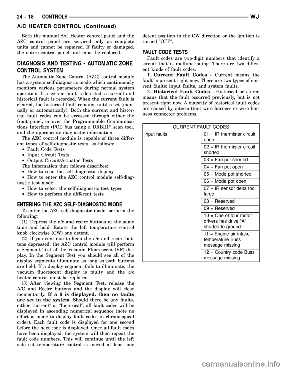
CURRENT FAULT CODES
Input faults 01 = IR thermister circuit
open
02 = IR thermister circuit
shorted
03 = Fan pot shorted
04 = Fan pot open
05 = Mode pot shorted
06 = Mode pot open
07 = IR sensor delta too
large
08 = Reserved
09 = Reserved
10 = One of four motor
drivers has drive9A9
shorted to ground
11 = Engine air intake
temperature Buss
message missing
12 = Country code Buss
message missing
24 - 18 CONTROLSWJ
A/C HEATER CONTROL (Continued)
Page 2098 of 2199

(2)If there are no fault codes, the ª00º dis-
play value will remain in the VF window.Should
there be any codes, each will be displayed for one
second in ascending numerical sequence (note: no
effort is made to display faults in the order they
occurred). The left side set temperature display will
be blanked and the right side set temperature dis-
play will indicate current and historical codes (8 his-
torical max) presently active. Once all codes have
been displayed, the system will repeat the fault code
numbers. This will continue until the left side set
temperature control is moved at least one detent
position in either direction, by pressing both the A/C
and Recirc buttons at the same time, or the ignition
is turned off. Record all of the fault codes, then see
the Current and Historical Fault Code charts for the
descriptions.
CLEARING FAULT CODES
Current faults cannot be electronically cleared.
Repair must be made to the system to eliminate the
fault causing code. Historical fault codes can be
cleared manually, or automatically. To clear a histor-
ical fault manually, depress and hold either the A/C
or Recirc button for at least three seconds while the
display is in the fault code mode of operation. Histor-
ical fault codes are cleared automatically when the
corresponding current fault code has been cleared,
and has remained cleared for a number of ignition
cycles. The faults have been cleared when two hori-
zontal bars appear in the Test Selector display.
EXITING SELF-DIAGNOSTIC MODE
The self-diagnostic mode can be exited by pressing
both the A/C and Recirc buttons at the same time, or
turning off the ignition.
MONITOR CURRENT PARAMETERS
While in the display fault code mode of operation,
current system parameters can also be monitored
and/or forced. Rotating the left side set temperature
control clockwise will increase the pointer number
while rotating the control counter clockwise will
decrease the pointer number. Rotating the right set
temperature control will have no impact on pointer
value or the value of the parameter being monitored.
Once the desired pointer number has been selected,
pressing either the AC or Recirc buttons will display
the current value of the selected parameter.The
right side set temperature display is only capa-
ble of displaying only values ranging from 0 to
99, the left side set temperature display is used
for values greater than 99. If the value is less
than 99, the left side set temperature display
remains blanked.While a parameter is being over-
ridden, the system will continue to function normallyexcept for the parameter which is being manually
controlled.
For values < 0, the9G9segment in the left side set
temperature Most Significant Digit (MSD)(or left-
most number in the pair) will be used to indicate a
negative number. For values between -01 to -99 the
Least Significant Digit (LSD)(or right-most number
of the pair) in the left side set temperature will
remain blank. System control of parameter being dis-
played can be overridden by rotating the right set
temperature control in either direction. Rotating the
right temperature control in the CW direction, the
selected parameter value is overridden and incre-
mented beginning at the value which was being dis-
played. Rotating the right temperature control in the
CCW direction, the selected parameter value is over-
ridden and decremented beginning at the value
which was being displayed. The rate at which incre-
menting and decrement occurs is one unit value per
set temperature detent position.
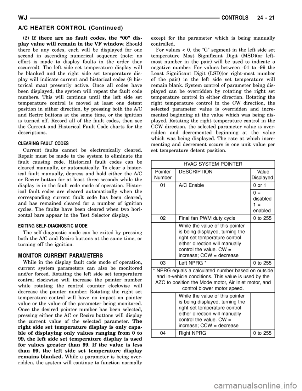
HVAC SYSTEM POINTER
Pointer
NumberDESCRIPTION Value
Displayed
01 A/C Enable 0 or 1
0=
disabled
1=
enabled
02 Final fan PWM duty cycle 0 to 255
While the value of this pointer
is being displayed, turning the
right set temperature control
either direction will manually
control the value. CW =
increase; CCW = decrease
03 Left NPRG * 0 to 255
* NPRG equals a calculated number based on outside
and in-vehicle conditions. This value is used by the
AZC to position the Mode motor, Air Inlet motor, and
control blower motor speed.
While the value of this pointer
is being displayed, turning the
right set temperature control
either direction will manually
control the value. CW =
increase; CCW = decrease
04 Right NPRG 0 to 255
WJCONTROLS 24 - 21
A/C HEATER CONTROL (Continued)
Page 2099 of 2199

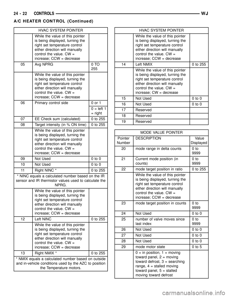
HVAC SYSTEM POINTER
While the value of this pointer
is being displayed, turning the
right set temperature control
either direction will manually
control the value. CW =
increase; CCW = decrease
05 Avg NPRG 0 TO
255
While the value of this pointer
is being displayed, turning the
right set temperature control
either direction will manually
control the value. CW =
increase; CCW = decrease
06 Primary control side 0 or 1
0 = left 1
= right
07 EE Check sum (calculated) 0 to 255
08 Target intensity (in % ON time) 0 to 255
While the value of this pointer
is being displayed, turning the
right set temperature control
either direction will manually
control the value. CW =
increase; CCW = decrease
09 Not Used 0 to 0
10 Not Used 0 to 0
11 Right NINC * 0 to 255
* NINC equals a calculated number based on the IR
sensor and IR thermistor values used to calculate the
NPRG.
While the value of this pointer
is being displayed, turning the
right set temperature control
either direction will manually
control the value. CW =
increase; CCW = decrease
12 Left NINC 0 to 255
While the value of this pointer
is being displayed, turning the
right set temperature control
either direction will manually
control the value. CW =
increase; CCW = decrease
13 Right NMIX * 0 to 255
* NMIX equals a calculated number based on outside
and in-vehicle conditions used by the AZC to position
the Temperature motors.HVAC SYSTEM POINTER
While the value of this pointer
is being displayed, turning the
right set temperature control
either direction will manually
control the value. CW =
increase; CCW = decrease
14 Left NMIX 0 to 255
While the value of this pointer
is being displayed, turning the
right set temperature control
either direction will manually
control the value. CW =
increase; CW = decrease
15 Not Used 0 to 0
16 Not Used 0 to 0
17 Reserved
18 Reserved
19 Reserved
MODE VALUE POINTER
Pointer
NumberDESCRIPTION Value
Displayed
20 mode range in delta counts 0 to
9999
21 Current mode position (in
counts)0to
9999
22 mode target position in ratio 0 to 255
While the value of this pointer
is being displayed, turning the
right set temperature control
either direction will manually
control the value. CW =
increase; CCW = decrease
23 mode target position in counts 0 to
9999
24 Not Used 0 to 0
25 number of valve moves since
last index0to
9999
26 Not Used 0 to 0
27 Not Used 0 to 0
28 Not Used 0 to 0
29 mode motor state 0 to 5
0 = in position, 1 = moving
toward panel, 2 = moving
toward defrost, 3 = searching
range, 4 = stalled moving
toward panel, 5 = stalled
moving toward defrost
24 - 22 CONTROLSWJ
A/C HEATER CONTROL (Continued)