2002 JEEP GRAND CHEROKEE left turn
[x] Cancel search: left turnPage 1329 of 2199
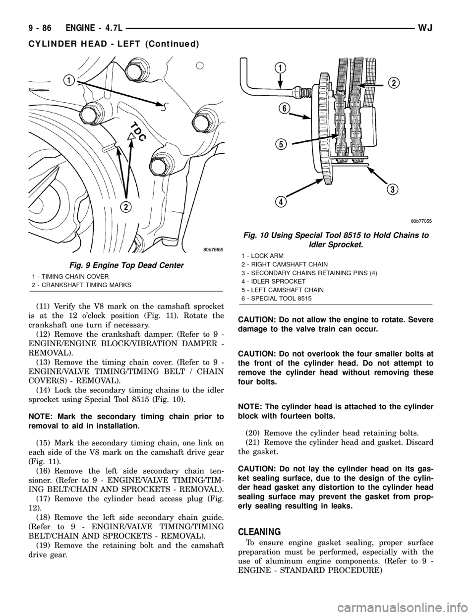
(11) Verify the V8 mark on the camshaft sprocket
is at the 12 o'clock position (Fig. 11). Rotate the
crankshaft one turn if necessary.
(12) Remove the crankshaft damper. (Refer to 9 -
ENGINE/ENGINE BLOCK/VIBRATION DAMPER -
REMOVAL).
(13) Remove the timing chain cover. (Refer to 9 -
ENGINE/VALVE TIMING/TIMING BELT / CHAIN
COVER(S) - REMOVAL).
(14) Lock the secondary timing chains to the idler
sprocket using Special Tool 8515 (Fig. 10).
NOTE: Mark the secondary timing chain prior to
removal to aid in installation.
(15) Mark the secondary timing chain, one link on
each side of the V8 mark on the camshaft drive gear
(Fig. 11).
(16) Remove the left side secondary chain ten-
sioner. (Refer to 9 - ENGINE/VALVE TIMING/TIM-
ING BELT/CHAIN AND SPROCKETS - REMOVAL).
(17) Remove the cylinder head access plug (Fig.
12).
(18) Remove the left side secondary chain guide.
(Refer to 9 - ENGINE/VALVE TIMING/TIMING
BELT/CHAIN AND SPROCKETS - REMOVAL).
(19) Remove the retaining bolt and the camshaft
drive gear.CAUTION: Do not allow the engine to rotate. Severe
damage to the valve train can occur.
CAUTION: Do not overlook the four smaller bolts at
the front of the cylinder head. Do not attempt to
remove the cylinder head without removing these
four bolts.
NOTE: The cylinder head is attached to the cylinder
block with fourteen bolts.
(20) Remove the cylinder head retaining bolts.
(21) Remove the cylinder head and gasket. Discard
the gasket.
CAUTION: Do not lay the cylinder head on its gas-
ket sealing surface, due to the design of the cylin-
der head gasket any distortion to the cylinder head
sealing surface may prevent the gasket from prop-
erly sealing resulting in leaks.
CLEANING
To ensure engine gasket sealing, proper surface
preparation must be performed, especially with the
use of aluminum engine components. (Refer to 9 -
ENGINE - STANDARD PROCEDURE)
Fig. 9 Engine Top Dead Center
1 - TIMING CHAIN COVER
2 - CRANKSHAFT TIMING MARKS
Fig. 10 Using Special Tool 8515 to Hold Chains to
Idler Sprocket.
1 - LOCK ARM
2 - RIGHT CAMSHAFT CHAIN
3 - SECONDARY CHAINS RETAINING PINS (4)
4 - IDLER SPROCKET
5 - LEFT CAMSHAFT CHAIN
6 - SPECIAL TOOL 8515
9 - 86 ENGINE - 4.7LWJ
CYLINDER HEAD - LEFT (Continued)
Page 1333 of 2199
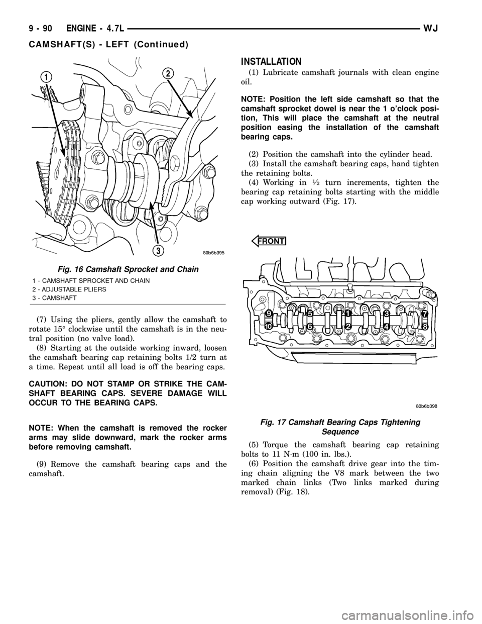
(7) Using the pliers, gently allow the camshaft to
rotate 15É clockwise until the camshaft is in the neu-
tral position (no valve load).
(8) Starting at the outside working inward, loosen
the camshaft bearing cap retaining bolts 1/2 turn at
a time. Repeat until all load is off the bearing caps.
CAUTION: DO NOT STAMP OR STRIKE THE CAM-
SHAFT BEARING CAPS. SEVERE DAMAGE WILL
OCCUR TO THE BEARING CAPS.
NOTE: When the camshaft is removed the rocker
arms may slide downward, mark the rocker arms
before removing camshaft.
(9) Remove the camshaft bearing caps and the
camshaft.
INSTALLATION
(1) Lubricate camshaft journals with clean engine
oil.
NOTE: Position the left side camshaft so that the
camshaft sprocket dowel is near the 1 o'clock posi-
tion, This will place the camshaft at the neutral
position easing the installation of the camshaft
bearing caps.
(2) Position the camshaft into the cylinder head.
(3) Install the camshaft bearing caps, hand tighten
the retaining bolts.
(4) Working in
1¤2turn increments, tighten the
bearing cap retaining bolts starting with the middle
cap working outward (Fig. 17).
(5) Torque the camshaft bearing cap retaining
bolts to 11 N´m (100 in. lbs.).
(6) Position the camshaft drive gear into the tim-
ing chain aligning the V8 mark between the two
marked chain links (Two links marked during
removal) (Fig. 18).
Fig. 16 Camshaft Sprocket and Chain
1 - CAMSHAFT SPROCKET AND CHAIN
2 - ADJUSTABLE PLIERS
3 - CAMSHAFT
Fig. 17 Camshaft Bearing Caps Tightening
Sequence
9 - 90 ENGINE - 4.7LWJ
CAMSHAFT(S) - LEFT (Continued)
Page 1338 of 2199
NOTE: All eight valve springs and valves are
removed in the same manner; this procedure only
covers one valve and valve spring.
(3) Using Special Tool C-3422±B or C-3422±C
Valve Spring Compressor and Special tool 8519
Adapter, compress the valve spring.
NOTE: It may be necessary to tap the top of the
valve spring to loosen the spring retainers locks
enough to be removed.
(4) Remove the two spring retainer lock halves.
NOTE: the valve spring is under tension use care
when releasing the valve spring compressor.
(5) Remove the valve spring compressor.
(6) Remove the spring retainer, and the spring.
NOTE: Check for sharp edges on the keeper
grooves. Remove any burrs from the valve stem
before removing the valve from the cylinder head.
(7) Remove the valve from the cylinder head.
NOTE: The valve stem seals are common between
intake and exhaust.
(8) Remove the valve stem seal. Mark the valve for
proper installation.
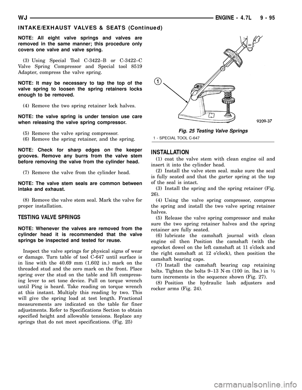
TESTING VALVE SPRINGS
NOTE: Whenever the valves are removed from the
cylinder head it is recommended that the valve
springs be inspected and tested for reuse.
Inspect the valve springs for physical signs of wear
or damage. Turn table of tool C-647 until surface is
in line with the 40.69 mm (1.602 in.) mark on the
threaded stud and the zero mark on the front. Place
spring over the stud on the table and lift compress-
ing lever to set tone device. Pull on torque wrench
until Ping is heard. Take reading on torque wrench
at this instant. Multiply this reading by two. This
will give the spring load at test length. Fractional
measurements are indicated on the table for finer
adjustments. Refer to Specifications Section to obtain
specified height and allowable tensions. Replace any
springs that do not meet specifications. (Fig. 25)
INSTALLATION
(1) coat the valve stem with clean engine oil and
insert it into the cylinder head.
(2) Install the valve stem seal. make sure the seal
is fully seated and that the garter spring at the top
of the seal is intact.
(3) Install the spring and the spring retainer (Fig.
26).
(4) Using the valve spring compressor, compress
the spring and install the two valve spring retainer
halves.
(5) Release the valve spring compressor and make
sure the two spring retainer halves and the spring
retainer are fully seated.
(6) lubricate the camshaft journal with clean
engine oil then Position the camshaft (with the
sprocket dowel on the left camshaft at 11 o'clock and
the right camshaft at 12 o'clock), then position the
camshaft bearing caps.
(7) Install the camshaft bearing cap retaining
bolts. Tighten the bolts 9±13 N´m (100 in. lbs.) in
1¤2
turn increments in the sequence shown (Fig. 27).
(8) Position the hydraulic lash adjusters and
rocker arms (Fig. 24).
Fig. 25 Testing Valve Springs
1 - SPECIAL TOOL C-647
WJENGINE - 4.7L 9 - 95
INTAKE/EXHAUST VALVES & SEATS (Continued)
Page 1344 of 2199
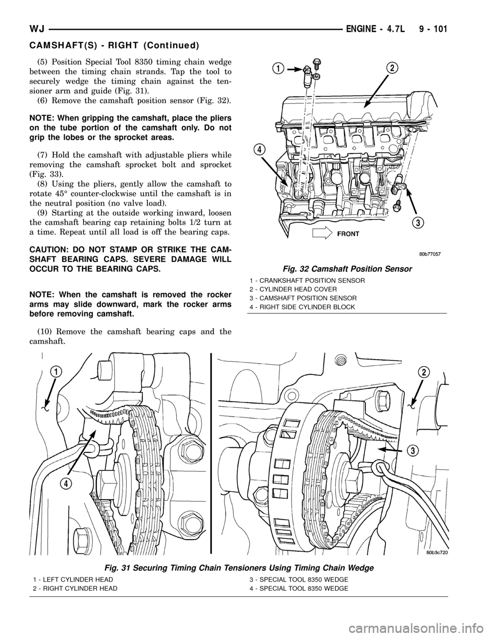
(5) Position Special Tool 8350 timing chain wedge
between the timing chain strands. Tap the tool to
securely wedge the timing chain against the ten-
sioner arm and guide (Fig. 31).
(6) Remove the camshaft position sensor (Fig. 32).
NOTE: When gripping the camshaft, place the pliers
on the tube portion of the camshaft only. Do not
grip the lobes or the sprocket areas.
(7) Hold the camshaft with adjustable pliers while
removing the camshaft sprocket bolt and sprocket
(Fig. 33).
(8) Using the pliers, gently allow the camshaft to
rotate 45É counter-clockwise until the camshaft is in
the neutral position (no valve load).
(9) Starting at the outside working inward, loosen
the camshaft bearing cap retaining bolts 1/2 turn at
a time. Repeat until all load is off the bearing caps.
CAUTION: DO NOT STAMP OR STRIKE THE CAM-
SHAFT BEARING CAPS. SEVERE DAMAGE WILL
OCCUR TO THE BEARING CAPS.
NOTE: When the camshaft is removed the rocker
arms may slide downward, mark the rocker arms
before removing camshaft.
(10) Remove the camshaft bearing caps and the
camshaft.
Fig. 31 Securing Timing Chain Tensioners Using Timing Chain Wedge
1 - LEFT CYLINDER HEAD
2 - RIGHT CYLINDER HEAD3 - SPECIAL TOOL 8350 WEDGE
4 - SPECIAL TOOL 8350 WEDGE
Fig. 32 Camshaft Position Sensor
1 - CRANKSHAFT POSITION SENSOR
2 - CYLINDER HEAD COVER
3 - CAMSHAFT POSITION SENSOR
4 - RIGHT SIDE CYLINDER BLOCK
WJENGINE - 4.7L 9 - 101
CAMSHAFT(S) - RIGHT (Continued)
Page 1349 of 2199
(4) Remove the two spring retainer lock halves.
NOTE: the valve spring is under tension use care
when releasing the valve spring compressor.
(5) Remove the valve spring compressor.
(6) Remove the spring retainer, and the spring.
NOTE: Check for sharp edges on the keeper
grooves. Remove any burrs from the valve stem
before removing the valve from the cylinder head.
(7) Remove the valve from the cylinder head.
NOTE: The valve stem seals are common between
intake and exhaust.
(8) Remove the valve stem seal. Mark the valve for
proper installation.
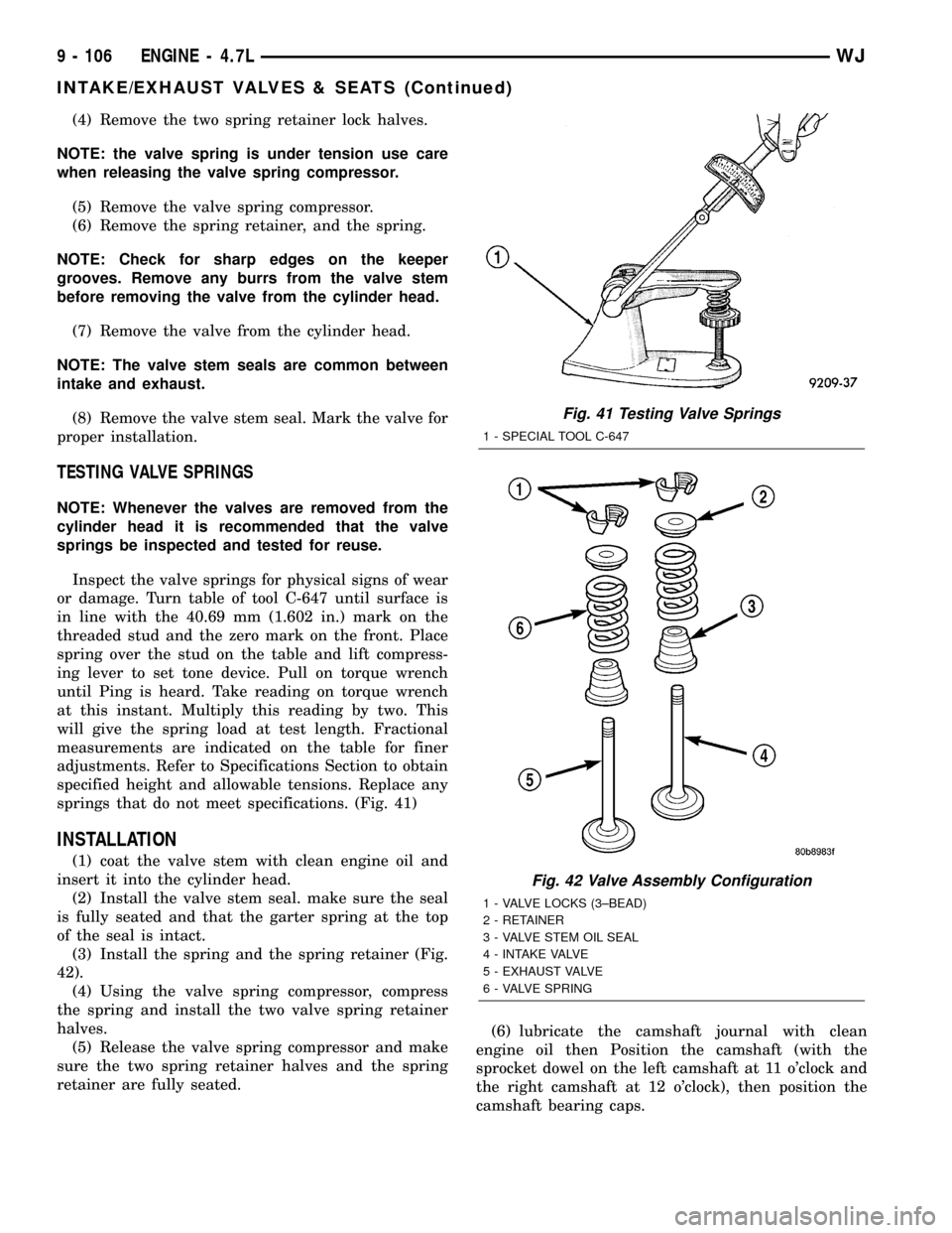
TESTING VALVE SPRINGS
NOTE: Whenever the valves are removed from the
cylinder head it is recommended that the valve
springs be inspected and tested for reuse.
Inspect the valve springs for physical signs of wear
or damage. Turn table of tool C-647 until surface is
in line with the 40.69 mm (1.602 in.) mark on the
threaded stud and the zero mark on the front. Place
spring over the stud on the table and lift compress-
ing lever to set tone device. Pull on torque wrench
until Ping is heard. Take reading on torque wrench
at this instant. Multiply this reading by two. This
will give the spring load at test length. Fractional
measurements are indicated on the table for finer
adjustments. Refer to Specifications Section to obtain
specified height and allowable tensions. Replace any
springs that do not meet specifications. (Fig. 41)
INSTALLATION
(1) coat the valve stem with clean engine oil and
insert it into the cylinder head.
(2) Install the valve stem seal. make sure the seal
is fully seated and that the garter spring at the top
of the seal is intact.
(3) Install the spring and the spring retainer (Fig.
42).
(4) Using the valve spring compressor, compress
the spring and install the two valve spring retainer
halves.
(5) Release the valve spring compressor and make
sure the two spring retainer halves and the spring
retainer are fully seated.(6) lubricate the camshaft journal with clean
engine oil then Position the camshaft (with the
sprocket dowel on the left camshaft at 11 o'clock and
the right camshaft at 12 o'clock), then position the
camshaft bearing caps.
Fig. 41 Testing Valve Springs
1 - SPECIAL TOOL C-647
Fig. 42 Valve Assembly Configuration
1 - VALVE LOCKS (3±BEAD)
2 - RETAINER
3 - VALVE STEM OIL SEAL
4 - INTAKE VALVE
5 - EXHAUST VALVE
6 - VALVE SPRING
9 - 106 ENGINE - 4.7LWJ
INTAKE/EXHAUST VALVES & SEATS (Continued)
Page 1421 of 2199
FUEL DELIVERY
DESCRIPTION
The fuel delivery system consists of:
²the fuel pump module containing the electric
fuel pump, fuel gauge sending unit (fuel level sensor)
and a separate fuel filter located at bottom of pump
module
²a separate combination fuel filter/fuel pressure
regulator
²fuel tubes/lines/hoses
²quick-connect fittings
²fuel injector rail
²fuel injectors
²fuel tank
²fuel tank filler/vent tube assembly
²fuel tank filler tube cap
²accelerator pedal
²throttle cable
OPERATION
The fuel tank assembly consists of: the fuel tank,
fuel tank shield, fuel tank straps, fuel pump module
assembly, fuel pump module locknut/gasket, and fuel
tank check valve (refer to Emission Control System
for fuel tank check valve information).
A fuel filler/vent tube assembly using a pressure/
vacuum, 1/4 turn fuel filler cap is used. The fuel
filler tube contains a flap door located below the fuel
fill cap.
Also to be considered part of the fuel system is the
evaporation control system. This is designed to
reduce the emission of fuel vapors into the atmo-
sphere. The description and function of the Evapora-
tive Control System is found in Emission Control
Systems.
Both fuel filters (at bottom of fuel pump module
and within fuel pressure regulator) are designed for
extended service. They do not require normal sched-
uled maintenance. Filters should only be replaced if
a diagnostic procedure indicates to do so.
DIAGNOSIS AND TESTING
FUEL PRESSURE LEAK DOWN TEST
Use this test in conjunction with the Fuel Pump
Pressure Test and Fuel Pump Capacity Test.
Check Valve Operation:The electric fuel pump
outlet contains a one-way check valve to prevent fuel
flow back into the tank and to maintain fuel supply
line pressure (engine warm) when pump is not oper-
ational. It is also used to keep the fuel supply line
full of gasoline when pump is not operational. After
the vehicle has cooled down, fuel pressure may drop
to 0 psi (cold fluid contracts), but liquid gasoline willremain in fuel supply line between the check valve
and fuel injectors.Fuel pressure that has
dropped to 0 psi on a cooled down vehicle
(engine off) is a normal condition.When the elec-
tric fuel pump is activated, fuel pressure should
immediately(1±2 seconds) rise to specification.
Abnormally long periods of cranking to restart a
hotengine that has been shut down for a short
period of time may be caused by:
²Fuel pressure bleeding past a fuel injector(s).
²Fuel pressure bleeding past the check valve in
the fuel pump module.
²A defective fuel filter/pressure regulator.
Two #6539, 5/16º, Fuel Line Pressure Test Adapter
Hose Tools are required for the following tests.
(1) Release fuel system pressure. Refer to Fuel
Pressure Release Procedure.
(2) Raise vehicle.
Fuel Line Identification:The fuel filter/pressure
regulator is located in front of the fuel tank and
above the rear axle. It is transversely mounted to a
chassis crossmember (left-to-right). The filter/regula-
tor is equipped with 3 fuel line fittings (2 at one end
and 1 at the other end). The single fitting facing the
left side of the vehicle is the supply line to the fuel
rail (Fig. 1) . The 2 fittings facing the right side of
the vehicle are connected to the fuel tank. Of these 2
fittings, the fitting towards thefrontis used for fuel
return to the fuel tank. The fitting towards therear
is a pressure line. Thisrearfitting must be discon-
nected for the following step.
(3) See previous step. Disconnect fuel pressure line
atrearof filter/regulator. This is a 5/169quick-con-
nect fitting (Fig. 1) . Refer to Quick-Connect Fittings
for procedures.
(4) Obtain correct Fuel Line Pressure Test Adapter
Hose Tool # 6539 for 5/16º fuel lines. Connect one
end of this Special Tool into the disconnected fuel
pressure line. Connect the other end of the Tool into
fitting on filter/regulator.
(5) Lower vehicle.
(6) Disconnect the fuel inlet line at fuel rail. Refer
to Quick-Connect Fittings for procedures. On some
engines, air cleaner housing removal may be neces-
sary before fuel line disconnection.
(7) Obtain a second Fuel Line Pressure Test
Adapter Hose Tool # 6539 for 5/16º fuel lines. Con-
nect this tool between disconnected fuel line and fuel
rail (Fig. 2) .
(8) Connect the 0-414 kPa (0-60 psi) fuel pressure
test gauge (from Gauge Set 5069) to the test port on
the appropriate Adaptor Tool.NOTE: The DRB III
Scan Tool along with the PEP module, the 500
psi pressure transducer, and the transducer-to-
test port adapter may also be used in place of
the fuel pressure gauge.
14 - 2 FUEL DELIVERYWJ
Page 1424 of 2199
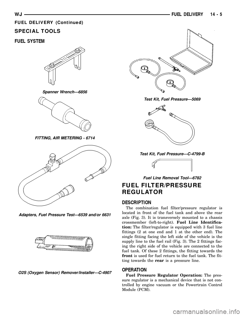
SPECIAL TOOLS
FUEL SYSTEM
FUEL FILTER/PRESSURE
REGULATOR
DESCRIPTION
The combination fuel filter/pressure regulator is
located in front of the fuel tank and above the rear
axle (Fig. 3). It is transversely mounted to a chassis
crossmember (left-to-right).Fuel Line Identifica-
tion:The filter/regulator is equipped with 3 fuel line
fittings (2 at one end and 1 at the other end). The
single fitting facing the left side of the vehicle is the
supply line to the fuel rail (Fig. 3). The 2 fittings fac-
ing the right side of the vehicle are connected to the
fuel tank. Of these 2 fittings, the fitting towards the
frontis used for fuel return to the fuel tank. The fit-
ting towards therearis a pressure line.
OPERATION
Fuel Pressure Regulator Operation:The pres-
sure regulator is a mechanical device that is not con-
trolled by engine vacuum or the Powertrain Control
Module (PCM).
Spanner WrenchÐ6856
FITTING, AIR METERING - 6714
Adapters, Fuel Pressure TestÐ6539 and/or 6631
O2S (Oxygen Sensor) Remover/InstallerÐC-4907
Test Kit, Fuel PressureÐ5069
Test Kit, Fuel PressureÐC-4799-B
Fuel Line Removal ToolÐ6782
WJFUEL DELIVERY 14 - 5
FUEL DELIVERY (Continued)
Page 1439 of 2199
(19) Disconnect fuel return line at fuel filter/fuel
pressure regulator (Fig. 36). Refer to Quick-Connect
Fittings for procedures.
(20) Disconnect fuel pressure line at fuel filter/fuel
pressure regulator (Fig. 36). Refer to Quick-Connect
Fittings for procedures.
(21) Disconnect EVAP canister vent line near front
of tank (Fig. 36).
(22) Disconnect fuel pump module electrical con-
nector (pigtail harness) near front of tank (Fig. 36).
Harness connector is clipped to body.
(23) Remove left / front tank support bracket bolt
at frame (Fig. 37).
(24)WITHOUT TRAILER HITCH:Remove tank-
to-frame mounting bolts (Fig. 39). Remove rear tank
support bracket bolts at frame (Fig. 38). Carefully
lower tank until clear of vehicle. Place tank on floor.
(25)WITH TRAILER HITCH:Remove tank /
hitch mounting bolts (Fig. 40). Carefully lower tank
until clear of vehicle. Place tank on floor.
(26) If necessary, separate skid plate from fuel
tank by removing 2 fuel tank strap nuts (Fig. 39) and
remove 2 tank straps.
(27) If fuel pump module removal is necessary,
refer to Fuel Pump Module Removal/Installation.
(28) If hoses are to be removed at fuel tank end,
note painted alignment (indexing) markings on
hoses, and molded indexing tangs on tank before
removal. Remove hoses.
(29) If necessary, remove 3 fuel filler tube assem-
bly mounting bolts (Fig. 41) and remove fuel filler
tube.
INSTALLATION
CAUTION: HANDLE EVAP, LDP AND ORVR VAPOR /
VACUUM LINES VERY CAREFULLY. THESE LINES
AND HOSES MUST BE FIRMLY CONNECTED.
CHECK THE VAPOR/VACUUM LINES AT THE LDP,
LDP FILTER, EVAP CANISTER, EVAP CANISTER
PURGE SOLENOID AND ORVR COMPONENTS FOR
DAMAGE OR LEAKS. IF A LEAK IS PRESENT, A
DIAGNOSTIC TROUBLE CODE (DTC) MAY BE SET.
(1) If necessary, position fuel filler tube assembly
to body. Install 3 bolts and tighten to 2 N´m (15 in.
lbs.) torque.
(2) If necessary, connect quick-connect fittings to
fuel pump module.
(3) If fuel pump module is being installed, refer to
Fuel Pump Module Removal/Installation.
(4) Install fuel fill/vent hoses to tank fittings. To
prevent hoses from kinking, rotate each hose until
painted indexing mark on hose is aligned to molded
indexing tang on tank.
(5) Install hose clamps to hoses. Refer to Torque
Specifications.(6) If necessary, position fuel tank into skid plate.
Install 2 tank straps and 2 strap nuts (Fig. 39). Refer
to Torque Specifications.
(7) Position fuel tank / skid plate assembly to
hydraulic jack.
(8) Raise tank into position to frame.
(9)WITH TRAILER HITCH:Position trailer
hitch and tow hooks (Fig. 40) to bottom of fuel tank.
Install bolts and nuts loosely.
(10)WITHOUT TRAILER HITCH:Install 2 rear
tank support brackets and bolts (Fig. 38). Install
tank-to-frame bolts. Do not tighten bolts / nuts at
this time.
(11) Install 1 left / front tank support bracket and
bolts / nuts (Fig. 37). Do not tighten bolts / nuts at
this time.
(12) Be sure fuel tank is properly aligned to frame
and body. Tighten all tank, tow hook and trailer
hitch bolts / nuts except for 3 support brackets.
Tighten all 3 (2 rear and 1 left / front) support
bracket bolts / nuts last. Refer to Torque Specifica-
tions.
(13)
(14) Connect fuel pump module pigtail harness
electrical connector near front of tank.
(15) Connect both fuel lines to fuel filter/fuel pres-
sure regulator. Refer to Quick-Connect Fittings for
procedures.
(16) Connect EVAP hose near front of tank.
(17) Position rear axle vent hose and install new
tie strap (Fig. 32).
(18) Install heat shield nuts / bolts (Fig. 35). Refer
to Torque Specifications.
(19) Connect ORVR hose elbow (Fig. 33) to top of
EVAP canister.
(20) Connect fuel vent hose to fuel vent tube (Fig.
32).
(21) Install fuel fill hose and clamp to fuel fill tube
(Fig. 32).
(22) Install 3 LDP mounting bolts (Fig. 29).
(23) While raising support bracket, connect LDP
wiring clip (Fig. 31). Install front section of two-piece
support bracket to rear section with 3 attaching bolts
located on bottom of support bracket (Fig. 30).
(24) Install support bracket brace bolt (Fig. 30).
(25) Tighten 2 support bracket nuts at frame rail
(Fig. 29).
(26) Install fuel tank-to-rear bumper fascia clips
(Fig. 34).
(27) Using new plastic rivets, install stone shield
behind left/rear wheel (Fig. 28).
(28) Install left rear wheel/tire.
(29) Lower vehicle and connect negative battery
cable to battery.
(30) Fill tank with fuel and check for leaks.
14 - 20 FUEL DELIVERYWJ
FUEL TANK (Continued)