2002 JEEP GRAND CHEROKEE left turn
[x] Cancel search: left turnPage 1461 of 2199
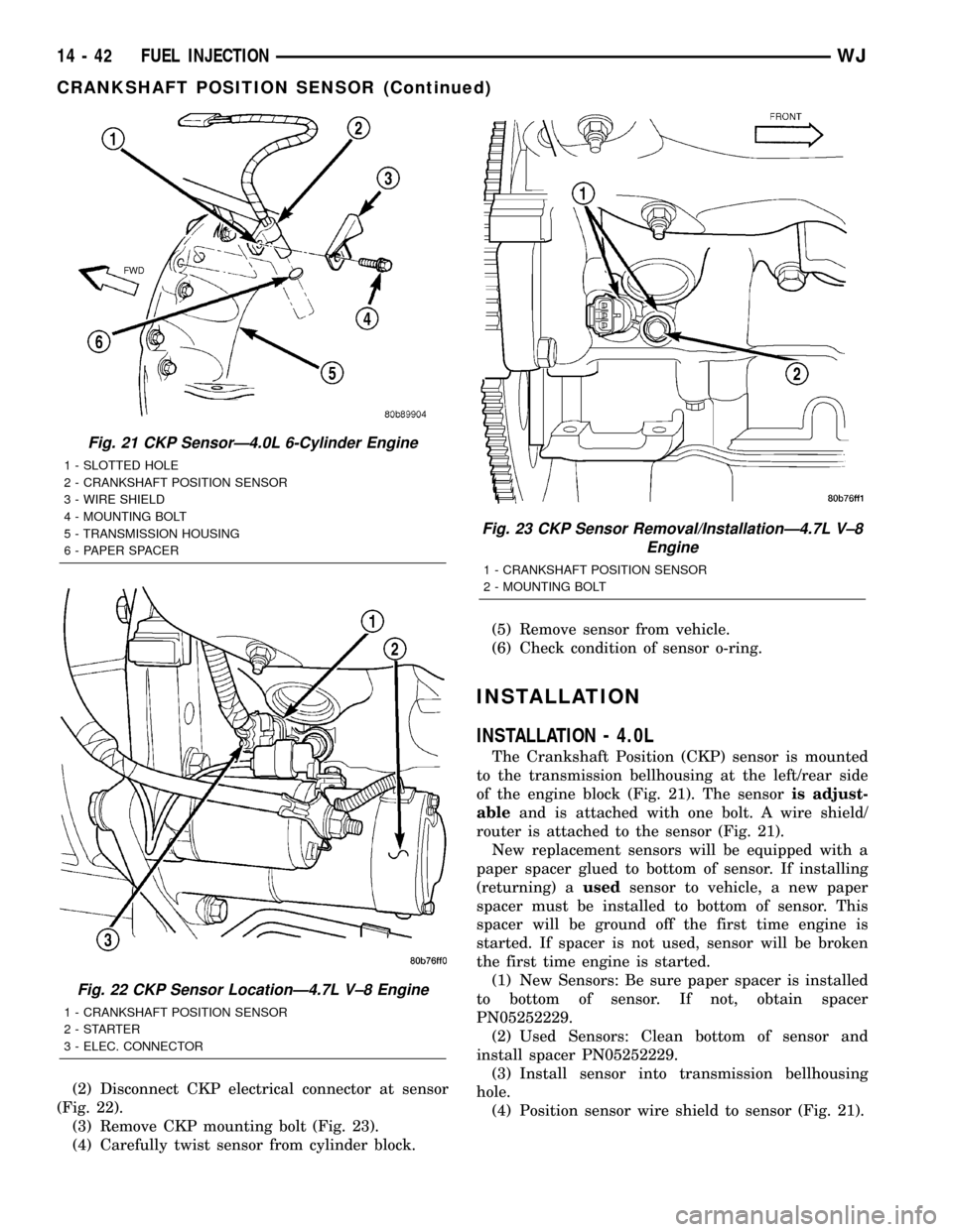
(2) Disconnect CKP electrical connector at sensor
(Fig. 22).
(3) Remove CKP mounting bolt (Fig. 23).
(4) Carefully twist sensor from cylinder block.(5) Remove sensor from vehicle.
(6) Check condition of sensor o-ring.
INSTALLATION
INSTALLATION - 4.0L
The Crankshaft Position (CKP) sensor is mounted
to the transmission bellhousing at the left/rear side
of the engine block (Fig. 21). The sensoris adjust-
ableand is attached with one bolt. A wire shield/
router is attached to the sensor (Fig. 21).
New replacement sensors will be equipped with a
paper spacer glued to bottom of sensor. If installing
(returning) ausedsensor to vehicle, a new paper
spacer must be installed to bottom of sensor. This
spacer will be ground off the first time engine is
started. If spacer is not used, sensor will be broken
the first time engine is started.
(1) New Sensors: Be sure paper spacer is installed
to bottom of sensor. If not, obtain spacer
PN05252229.
(2) Used Sensors: Clean bottom of sensor and
install spacer PN05252229.
(3) Install sensor into transmission bellhousing
hole.
(4) Position sensor wire shield to sensor (Fig. 21).
Fig. 21 CKP SensorÐ4.0L 6-Cylinder Engine
1 - SLOTTED HOLE
2 - CRANKSHAFT POSITION SENSOR
3 - WIRE SHIELD
4 - MOUNTING BOLT
5 - TRANSMISSION HOUSING
6 - PAPER SPACER
Fig. 22 CKP Sensor LocationÐ4.7L V±8 Engine
1 - CRANKSHAFT POSITION SENSOR
2-STARTER
3 - ELEC. CONNECTOR
Fig. 23 CKP Sensor Removal/InstallationÐ4.7L V±8
Engine
1 - CRANKSHAFT POSITION SENSOR
2 - MOUNTING BOLT
14 - 42 FUEL INJECTIONWJ
CRANKSHAFT POSITION SENSOR (Continued)
Page 1465 of 2199
INSTALLATION
INSTALLATION - 4.0L
The IAC motor is located on the throttle body.
(1) Install IAC motor to throttle body.
(2) Install and tighten two mounting bolts (screws)
to 7 N´m (60 in. lbs.) torque.
(3) Install electrical connector.
(4) Install air cleaner duct/air box to throttle body.
INSTALLATION - 4.7L
(1) Install IAC motor to throttle body.
(2) Install and tighten two mounting bolts (screws)
to 7 N´m (60 in. lbs.) torque.
(3) Install electrical connector.
(4) Install air duct/air box to throttle body.
INTAKE AIR TEMPERATURE
SENSOR
DESCRIPTION
The 2±wire Intake Manifold Air Temperature (IAT)
sensor is installed in the intake manifold with the
sensor element extending into the air stream.
The IAT sensor is a two-wire Negative Thermal
Coefficient (NTC) sensor. Meaning, as intake mani-
fold temperature increases, resistance (voltage) in the
sensor decreases. As temperature decreases, resis-
tance (voltage) in the sensor increases.
OPERATION
The IAT sensor provides an input voltage to the
Powertrain Control Module (PCM) indicating the
density of the air entering the intake manifold based
upon intake manifold temperature. At key-on, a
5±volt power circuit is supplied to the sensor from
the PCM. The sensor is grounded at the PCM
through a low-noise, sensor-return circuit.
The PCM uses this input to calculate the following:
²Injector pulse-width
²Adjustment of spark timing (to help prevent
spark knock with high intake manifold air-charge
temperatures)
The resistance values of the IAT sensor is the same
as for the Engine Coolant Temperature (ECT) sensor.
REMOVAL
REMOVAL - 4.0L
The Intake Manifold Air Temperature (IAT) sensor
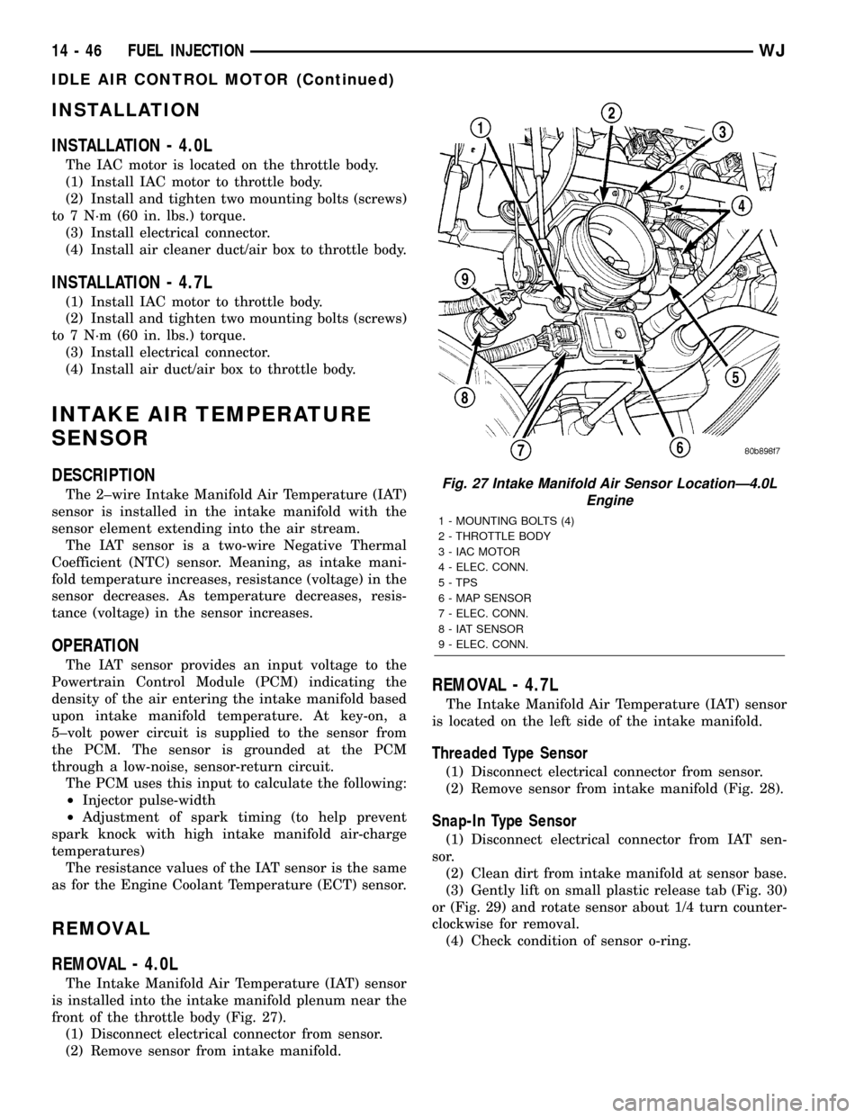
is installed into the intake manifold plenum near the
front of the throttle body (Fig. 27).
(1) Disconnect electrical connector from sensor.
(2) Remove sensor from intake manifold.
REMOVAL - 4.7L
The Intake Manifold Air Temperature (IAT) sensor
is located on the left side of the intake manifold.
Threaded Type Sensor
(1) Disconnect electrical connector from sensor.
(2) Remove sensor from intake manifold (Fig. 28).
Snap-In Type Sensor
(1) Disconnect electrical connector from IAT sen-
sor.
(2) Clean dirt from intake manifold at sensor base.
(3) Gently lift on small plastic release tab (Fig. 30)
or (Fig. 29) and rotate sensor about 1/4 turn counter-
clockwise for removal.
(4) Check condition of sensor o-ring.
Fig. 27 Intake Manifold Air Sensor LocationÐ4.0L
Engine
1 - MOUNTING BOLTS (4)
2 - THROTTLE BODY
3 - IAC MOTOR
4 - ELEC. CONN.
5 - TPS
6 - MAP SENSOR
7 - ELEC. CONN.
8 - IAT SENSOR
9 - ELEC. CONN.
14 - 46 FUEL INJECTIONWJ
IDLE AIR CONTROL MOTOR (Continued)
Page 1469 of 2199

The other two heater elements (downstream sen-
sors 1/2 and 2/2) are controlled by the downstream
heater relay through output signals from the PCM.
To avoid a large simultaneous current surge, power
is delayed to the 2 downstream heater elements by
the PCM for approximately 2 seconds.
REMOVAL
(1) Remove PDC cover.
(2) Remove relay from PDC.
(3) Check condition of relay terminals and PDC
connector terminals for damage or corrosion. Repair
if necessary before installing relay.
(4) Check for pin height (pin height should be the
same for all terminals within the PDC connector).
Repair if necessary before installing relay.
INSTALLATION
(1) Install relay to PDC.
(2) Install cover to PDC.
O2S SENSOR
DESCRIPTION
The Oxygen Sensors (O2S) are attached to, and
protrude into the vehicle exhaust system. Depending
on the emission package, the vehicle may use a total
of either 2 or 4 sensors.
Federal Emissions Package:Two sensors are
used: upstream (referred to as 1/1) and downstream
(referred to as 1/2). With this emission package, the
upstream sensor (1/1) is located just before the main
catalytic convertor. The downstream sensor (1/2) is
located just after the main catalytic convertor.
4.7L V-8 With California Emissions Package:
On this emissions package, 4 sensors are used: 2
upstream (referred to as 1/1 and 2/1) and 2 down-
stream (referred to as 1/2 and 2/2). With this emis-
sion package, the right upstream sensor (2/1) is
located in the right exhaust downpipe just before the
mini-catalytic convertor. The left upstream sensor
(1/1) is located in the left exhaust downpipe just
before the mini-catalytic convertor. The right down-
stream sensor (2/2) is located in the right exhaust
downpipe just after the mini-catalytic convertor, and
before the main catalytic convertor. The left down-
stream sensor (1/2) is located in the left exhaust
downpipe just after the mini-catalytic convertor, and
before the main catalytic convertor.
4.0L 6±Cylinder With California Emissions
Package:On this emissions package, 4 sensors are
used: 2 upstream (referred to as 1/1 and 2/1) and 2
downstream (referred to as 1/2 and 2/2). With this
emission package, the rear/upper upstream sensor
(2/1) is located in the exhaust downpipe just beforethe rear mini-catalytic convertor. The front/upper
upstream sensor (1/1) is located in the exhaust down-
pipe just before the front mini-catalytic convertor.
The rear/lower downstream sensor (2/2) is located in
the exhaust downpipe just after the rear mini-cata-
lytic convertor, and before the main catalytic conver-
tor. The front/lower downstream sensor (1/2) is
located in the exhaust downpipe just after the front
mini-catalytic convertor, and before the main cata-
lytic convertor.
OPERATION
An O2 sensor is a galvanic battery that provides
the PCM with a voltage signal (0-1 volt) inversely
proportional to the amount of oxygen in the exhaust.
In other words, if the oxygen content is low, the volt-
age output is high; if the oxygen content is high the
output voltage is low. The PCM uses this information
to adjust injector pulse-width to achieve the
14.7±to±1 air/fuel ratio necessary for proper engine
operation and to control emissions.
The O2 sensor must have a source of oxygen from
outside of the exhaust stream for comparison. Cur-
rent O2 sensors receive their fresh oxygen (outside
air) supply through the O2 sensor case housing.
Four wires (circuits) are used on each O2 sensor: a
12±volt feed circuit for the sensor heating element; a
ground circuit for the heater element; a low-noise
sensor return circuit to the PCM, and an input cir-
cuit from the sensor back to the PCM to detect sen-
sor operation.
Oxygen Sensor Heaters/Heater Relays:
Depending on the emissions package, the heating ele-
ments within the sensors will be supplied voltage
from either the ASD relay, or 2 separate oxygen sen-
sor relays. Refer to Wiring Diagrams to determine
which relays are used.
The O2 sensor uses a Positive Thermal Co-efficient
(PTC) heater element. As temperature increases,
resistance increases. At ambient temperatures
around 70ÉF, the resistance of the heating element is
approximately 4.5 ohms on 4.0L engines. It is
approximately 13.5 ohms on the 4.7L engine. As the
sensor's temperature increases, resistance in the
heater element increases. This allows the heater to
maintain the optimum operating temperature of
approximately 930É-1100ÉF (500É-600É C). Although
the sensors operate the same, there are physical dif-
ferences, due to the environment that they operate
in, that keep them from being interchangeable.
Maintaining correct sensor temperature at all
times allows the system to enter into closed loop
operation sooner. Also, it allows the system to remain
in closed loop operation during periods of extended
idle.
14 - 50 FUEL INJECTIONWJ
O2S HEATER RELAY (Continued)
Page 1482 of 2199
(8) Start engine and let idle long enough to circu-
late power steering fluid through flow/pressure test
gauge.
(9) Shut off the engine and check the fluid level,
add fluid as necessary. Start engine again and let
idle.
(10) The initial pressure reading should be
345-552 kPa (50-80 psi). If pressure is higher inspect
the hoses for restrictions and repair as necessary.
(11) Increase the engine speed to 1500 RPM and
read the flow meter. The reading should be 2.4 - 2.8
GPM, if the reading is below this specification the
pump should be replaced.
CAUTION: This next step involves testing maximum
pump pressure output and flow control valve oper-
ation. Do not leave valve closed for more than three
seconds as the pump could be damaged.
(12) Close valve fully three times for three seconds
and record highest pressure indicated each time.All
three readings must be at pump relief pressure
specifications and within 345 kPa (50 psi) of
each other.
²Pressures above specifications but not within
345 kPa (50 psi) of each other, replace pump.
²Pressures within 345 kPa (50 psi) of each other
but below specifications, replace pump.
CAUTION: Do not force the pump to operate against
the stops for more than 2 to 4 seconds at a time
because, pump damage will result.
(13) Open the test valve and turn the steering
wheel to the extreme left and right positions against
the stops. Record the highest pressure reading at
each position. Compare readings to the pump specifi-
cations chart. If pressures readings are not within 50
psi. of each other, the gear is leaking internally and
must be repaired.
GEAR INLET SPECIFICATIONS 4.0L & 4.7L
ENGINERELIEF
PRESSURE 50FLOW RATE
(GPM)
4.0L 9653 kPa (1400 psi)
1500 RPM 2.4 - 2.8
GPM
4.7L 9653 kPa (1450 psi)
PUMP MOTOR SPECIFICATIONS 4.7L
ENGINERELIEF
PRESSURE 50FLOW RATE
(GPM)
4.7L 9653 kPa (1900 psi)1100 RPM 2.4-2.8
GPM Minium
@ 200 psi
DIAGNOSIS AND TESTING - 4.7L -
HYDRAULIC
The following procedures are used to test the oper-
ation of the power steering and hydraulic fan sys-
tems on the vehicle. This test will provide the gallons
per minute (GPM) or flow rate of the power steering
pump along with any maximum relief pressure. Per-
form test anytime a power steering system problem
is present. This test will determine if the power
steering pump, hydraulic fan, and power steering
gear are not functioning properly. It will also deter-
mine if the flow coming out of the hydraulic fan
motor is sufficient for the power steering gear. The
following pressure and flow test is performed using
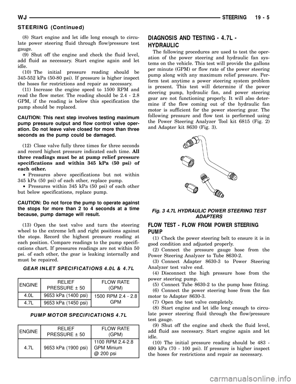
the Power Steering Analyzer Tool kit 6815 (Fig. 2)
and Adapter kit 8630 (Fig. 3).
FLOW TEST - FLOW FROM POWER STEERING
PUMP
(1) Check the power steering belt to ensure it is in
good condition and adjusted properly.
(2) Connect the pressure gauge hose from the
Power Steering Analyzer to Tube 8630-2.
(3) Connect Adapter 8630-3 to Power Steering
Analyzer test valve end.
(4) Disconnect the high pressure hose from the
power steering pump.
(5) Connect Tube 8630-2 to the pump hose fitting.
(6) Connect the power steering hose from the fan
motor to Adapter 8630-3.
(7) Open the test valve completely.
(8) Start engine and let idle long enough to circu-
late power steering fluid through the flow/pressure
test gauge.
(9) Shut off the engine and check the fluid level,
add fluid ass necessary. Start engine again and let
idle.
(10) The initial pressure reading should be 483 -
690 kPa (70 - 100 psi). If pressure is higher inspect
the hoses for restrictions and repair as necessary.
Fig. 3 4.7L HYDRAULIC POWER STEERING TEST
ADAPTERS
WJSTEERING 19 - 5
STEERING (Continued)
Page 1483 of 2199
(11) Increase the engine speed to 1100 rpm and
read the flow meter. The reading should be 2.6 GPM
minimum, if the reading is below this specification,
the pump should be replaced.
FLOW AND PRESSURE TEST - FLOW FROM
HYDRAULIC FAN MOTOR TO STEERING GEAR
(should be done if necessary after the Pump flow
test)
(1) Connect the pressure gauge hose from the
Power Steering Analyzer to Fitting 8630-1.
(2) Connect Adapter 8630-4 to Power Steering
Analyzer test valve end.
(3) Disconnect the high pressure hose from the
power steering gear.
(4) Connect Fitting 8630-1 to the high pressure
hose.
(5) Connect Adapter 8630-4 to the power steering
gear.
(6) Open the test valve completely.
(7) Start engine and let idle long enough to circu-
late power steering fluid through the flow/pressure
test gauge.
(8) Shut off the engine and check the fluid level,
add fluid ass necessary. Start engine again and let
idle.
(9) The initial pressure reading should be 345-552
kPa (50-80 psi). If pressure is higher inspect the
hoses for restrictions and repair as necessary.(10) Increase the engine speed to 1500 RPM and
read the flow meter. The reading should be 2.4 - 2.8
GPM if the reading is below this specification the fan
should be replaced.
CAUTION: This next step involves testing maximum
fan motor steering relief pressure. Do not leave the
valve closed for more than three seconds.
(11) Close the valve fully three times for three sec-
onds and record highest pressures indicated each
time. All three readings must be at fan motor steer-
ing relief pressures.
(12) Open the test valve and turn the steering
wheel to the extreme left and right positions against
the stops. Record the highest pressure readings at
each position. If pressure readings are not within 50
psi from each other, the gear is leaking internally
and must be repaired.
PUMP MOTOR SPECIFICATIONS 4.7L
ENGINERELIEF
PRESSURE 50FLOW RATE
(GPM)
4.7L 9653 kPa (1900 psi)1100 RPM 2.4-2.8
GPM Minium
@ 200 psi
19 - 6 STEERINGWJ
STEERING (Continued)
Page 1493 of 2199
GEAR
TABLE OF CONTENTS
page page
GEAR
DESCRIPTION.........................16
OPERATION...........................16
REMOVAL.............................16
INSTALLATION.........................16
ADJUSTMENTS
STEERING GEAR.....................18
SPECIFICATIONS
POWER STEERING GEAR..............18
SPECIAL TOOLS
POWER STEERING GEAR..............19
PITMAN SHAFT
REMOVAL.............................20INSTALLATION.........................20
PITMAN SHAFT BEARING
REMOVAL.............................22
INSTALLATION.........................22
PITMAN SHAFT SEAL
REMOVAL.............................22
INSTALLATION.........................23
RACK PISTON/VALVE ASSEMBLY
REMOVAL.............................23
INSTALLATION.........................25
STUB SHAFT HOUSING
REMOVAL.............................25
INSTALLATION.........................25
GEAR
DESCRIPTION
The power steering gear is a recirculating ball type
gear (Fig. 1) .
The following gear components can be serviced:
²Pitman Shaft and Cover
²Pitman Shaft Bearings
²Pitman Shaft Oil Seal/Dust Seal
²Stud Shaft Housing with Seal
²O-Rings and Teflon Rings
NOTE: If rack piston assembly is damaged the gear
must be replaced.
OPERATION
The gear acts as a rolling thread between the
worm shaft and rack piston. The worm shaft is sup-
ported by a thrust bearing at the lower end and a
bearing assembly at the upper end. When the worm
shaft is turned the rack piston moves. The rack pis-
ton teeth mesh with the pitman shaft. Turning the
worm shaft turns the pitman shaft, which turns the
steering linkage.
REMOVAL
(1) Place the front wheels in the straight ahead
position with the steering wheel centered and locked.
(2) Remove the air cleaner housing,(Refer to 9 -
ENGINE/AIR INTAKE SYSTEM/AIR CLEANER
HOUSING - REMOVAL).
(3) Drain or siphon the power steering system.(4) Remove the pressure and return lines (Fig.
2)from the steering gear. Refer to hose removal in
this section.
(5) Remove the column coupler shaft bolt (Fig.
2)and remove the shaft from the gear.
(6) Raise and support the vehicle.
(7) Remove the left front wheel and tire assembly.
(8) Remove the pitman arm from gear with Puller
C-4150A.
(9) Remove the windshield washer reservoir,(Refer
to 8 - ELECTRICAL/WIPERS/WASHERS/WASHER
RESERVOIR - REMOVAL).
(10) Remove the steering gear mounting bolts.
Remove the steering gear out of the engine compart-
ment (Fig. 3).
INSTALLATION
(1) Position the steering gear on the frame rail and
install the bolts. Tighten the bolts to 108 N´m (80 ft.
lbs.) torque.
(2) Install the pitman arm and tighten nut to 251
N´m (185 ft. lbs.).
(3) Install windshield washer reservoir,(Refer to 8 -
ELECTRICAL/WIPERS/WASHERS/WASHER RES-
ERVOIR - INSTALLATION).
(4) Install the wheel and tire assembly.
(5) Remove the support and lower the vehicle.
(6) Install the pressure and return hoses to the
steering gear and tighten to 20-38 N´m (14-28 ft.
lbs.).
(7) Install the column coupler shaft.
(8) Install the air cleaner housing,(Refer to 9 -
ENGINE/AIR INTAKE SYSTEM/AIR CLEANER
HOUSING - INSTALLATION).
19 - 16 GEARWJ
Page 1495 of 2199
ADJUSTMENTS
STEERING GEAR
NOTE: Adjusting the steering gear in the vehicle is
not recommended. Remove gear from the vehicle
and drain the fluid. Then mount gear in a vise to
perform adjustments.
OVER-CENTER
(1) Rotate the stub shaft with Socket 8343 from
stop to stop and count the number of turns.
(2) Center the stub shaft by rotating it from the
stop 1/2 of the total amount of turns.
(3) Place torque wrench and Socket 8343 in a ver-
tical position on the stub shaft. Rotate the wrench 45
degrees each side of the center and record the high-
est rotational torque in this range (Fig. 4) . This is
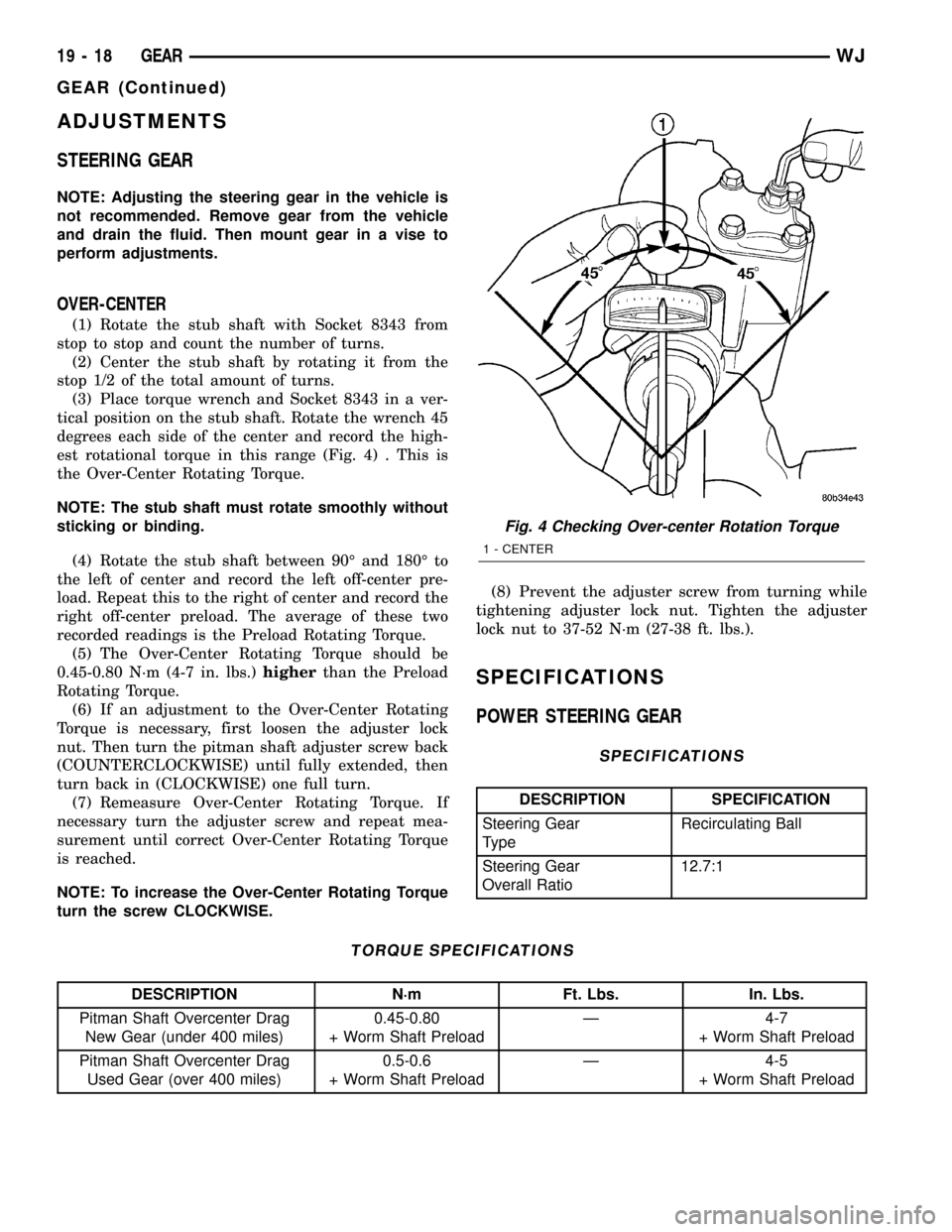
the Over-Center Rotating Torque.
NOTE: The stub shaft must rotate smoothly without
sticking or binding.
(4) Rotate the stub shaft between 90É and 180É to
the left of center and record the left off-center pre-
load. Repeat this to the right of center and record the
right off-center preload. The average of these two
recorded readings is the Preload Rotating Torque.
(5) The Over-Center Rotating Torque should be
0.45-0.80 N´m (4-7 in. lbs.)higherthan the Preload
Rotating Torque.
(6) If an adjustment to the Over-Center Rotating
Torque is necessary, first loosen the adjuster lock
nut. Then turn the pitman shaft adjuster screw back
(COUNTERCLOCKWISE) until fully extended, then
turn back in (CLOCKWISE) one full turn.
(7) Remeasure Over-Center Rotating Torque. If
necessary turn the adjuster screw and repeat mea-
surement until correct Over-Center Rotating Torque
is reached.
NOTE: To increase the Over-Center Rotating Torque
turn the screw CLOCKWISE.(8) Prevent the adjuster screw from turning while
tightening adjuster lock nut. Tighten the adjuster
lock nut to 37-52 N´m (27-38 ft. lbs.).
SPECIFICATIONS
POWER STEERING GEAR
SPECIFICATIONS
DESCRIPTION SPECIFICATION
Steering Gear
TypeRecirculating Ball
Steering Gear
Overall Ratio12.7:1
TORQUE SPECIFICATIONS
DESCRIPTION N´m Ft. Lbs. In. Lbs.
Pitman Shaft Overcenter Drag
New Gear (under 400 miles)0.45-0.80
+ Worm Shaft PreloadÐ 4-7
+ Worm Shaft Preload
Pitman Shaft Overcenter Drag
Used Gear (over 400 miles)0.5-0.6
+ Worm Shaft PreloadÐ 4-5
+ Worm Shaft Preload
Fig. 4 Checking Over-center Rotation Torque
1 - CENTER
19 - 18 GEARWJ
GEAR (Continued)
Page 1510 of 2199
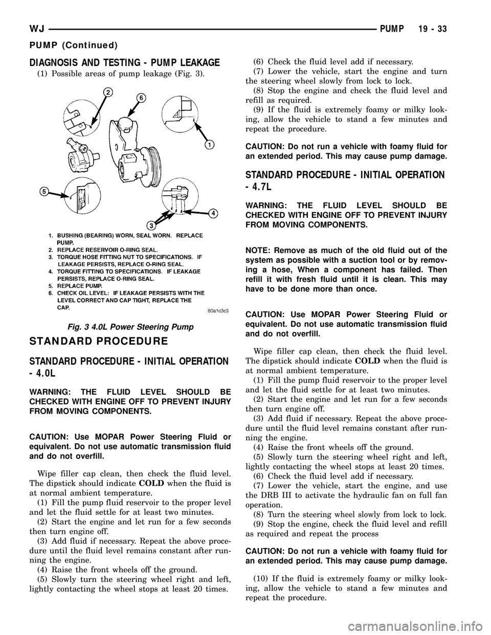
DIAGNOSIS AND TESTING - PUMP LEAKAGE
(1) Possible areas of pump leakage (Fig. 3).
STANDARD PROCEDURE
STANDARD PROCEDURE - INITIAL OPERATION
- 4.0L
WARNING: THE FLUID LEVEL SHOULD BE
CHECKED WITH ENGINE OFF TO PREVENT INJURY
FROM MOVING COMPONENTS.
CAUTION: Use MOPAR Power Steering Fluid or
equivalent. Do not use automatic transmission fluid
and do not overfill.
Wipe filler cap clean, then check the fluid level.
The dipstick should indicateCOLDwhen the fluid is
at normal ambient temperature.
(1) Fill the pump fluid reservoir to the proper level
and let the fluid settle for at least two minutes.
(2) Start the engine and let run for a few seconds
then turn engine off.
(3) Add fluid if necessary. Repeat the above proce-
dure until the fluid level remains constant after run-
ning the engine.
(4) Raise the front wheels off the ground.
(5) Slowly turn the steering wheel right and left,
lightly contacting the wheel stops at least 20 times.(6) Check the fluid level add if necessary.
(7) Lower the vehicle, start the engine and turn
the steering wheel slowly from lock to lock.
(8) Stop the engine and check the fluid level and
refill as required.
(9) If the fluid is extremely foamy or milky look-
ing, allow the vehicle to stand a few minutes and
repeat the procedure.
CAUTION: Do not run a vehicle with foamy fluid for
an extended period. This may cause pump damage.
STANDARD PROCEDURE - INITIAL OPERATION
- 4.7L
WARNING: THE FLUID LEVEL SHOULD BE
CHECKED WITH ENGINE OFF TO PREVENT INJURY
FROM MOVING COMPONENTS.
NOTE: Remove as much of the old fluid out of the
system as possible with a suction tool or by remov-
ing a hose, When a component has failed. Then
refill it with fresh fluid until it is clean. This may
have to be done more than once.
CAUTION: Use MOPAR Power Steering Fluid or
equivalent. Do not use automatic transmission fluid
and do not overfill.
Wipe filler cap clean, then check the fluid level.
The dipstick should indicateCOLDwhen the fluid is
at normal ambient temperature.
(1) Fill the pump fluid reservoir to the proper level
and let the fluid settle for at least two minutes.
(2) Start the engine and let run for a few seconds
then turn engine off.
(3) Add fluid if necessary. Repeat the above proce-
dure until the fluid level remains constant after run-
ning the engine.
(4) Raise the front wheels off the ground.
(5) Slowly turn the steering wheel right and left,
lightly contacting the wheel stops at least 20 times.
(6) Check the fluid level add if necessary.
(7) Lower the vehicle, start the engine, and use
the DRB III to activate the hydraulic fan on full fan
operation.
(8)
Turn the steering wheel slowly from lock to lock.
(9) Stop the engine, check the fluid level and refill
as required and repeat the process
CAUTION: Do not run a vehicle with foamy fluid for
an extended period. This may cause pump damage.
(10) If the fluid is extremely foamy or milky look-
ing, allow the vehicle to stand a few minutes and
repeat the procedure.
Fig. 3 4.0L Power Steering Pump
WJPUMP 19 - 33
PUMP (Continued)