2002 JEEP GRAND CHEROKEE Bearings
[x] Cancel search: BearingsPage 1280 of 2199
nal clearance an additional 0.0127 mm (0.0005 inch).
The clearance would then be 0.0381 mm (0.0015
inch).
CAUTION: Never use a pair of inserts that differ
more than one bearing size as a pair.
FOR EXAMPLE:DO NOT use a standard size
upper insert and a 0.051 mm (0.002 inch) undersize
lower insert.If the clearance exceeds specification using a pair
of 0.051 mm (0.002 inch) undersize bearing inserts,
measure crankshaft journal diameter with a
micrometer. If the journal diameter is correct, the
crankshaft bore in the cylinder block may be mis-
aligned, which requires cylinder block replacement or
machining to true bore.
Replace the crankshaft or grind to accept the
appropriate undersize bearing inserts if:
²Journal diameters 1 through 6 are less than
63.4517 mm (2.4981 inches)
²Journal 7 diameter is less than 63.4365 mm
(2.4975 inches).
Once the proper clearances have been obtained,
proceed to (Refer to 9 - ENGINE/ENGINE BLOCK/
CRANKSHAFT MAIN BEARINGS - INSTALLA-
TION).
JOURNAL DIAMETER (CRANKSHAFT REMOVED)
Remove the crankshaft from the cylinder block.
Clean the oil off the main bearing journal.
Determine the maximum diameter of the journal
with a micrometer. Measure at two locations 90É
apart at each end of the journal.
The maximum allowable taper and out of round is
0.013 mm (0.0005 inch). Compare the measured
diameter with the journal diameter specification
MAIN BEARING FITTING CHART . Select inserts
required to obtain the specified bearing-to-journal
clearance.
Install the crankshaft into the cylinder block.
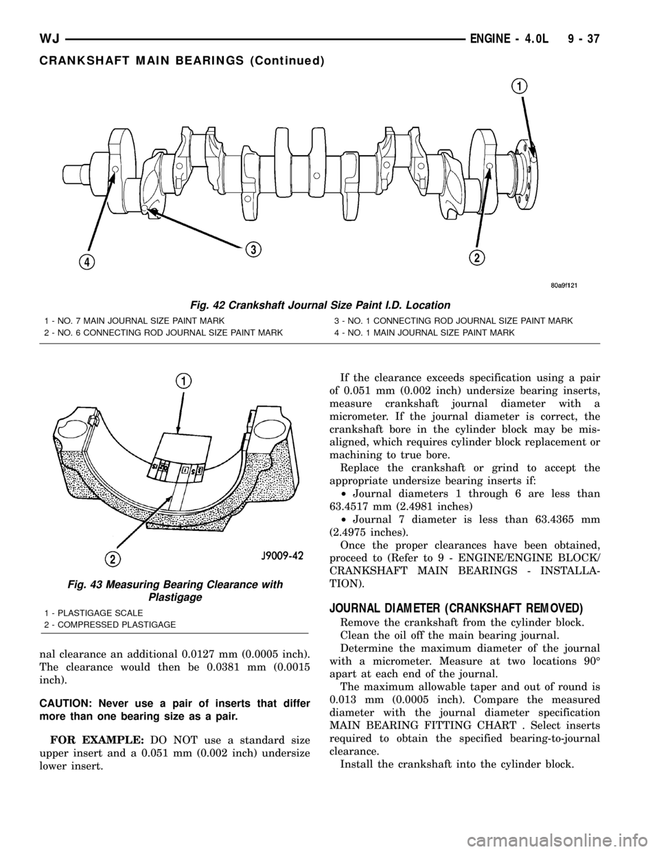
Fig. 42 Crankshaft Journal Size Paint I.D. Location
1 - NO. 7 MAIN JOURNAL SIZE PAINT MARK
2 - NO. 6 CONNECTING ROD JOURNAL SIZE PAINT MARK3 - NO. 1 CONNECTING ROD JOURNAL SIZE PAINT MARK
4 - NO. 1 MAIN JOURNAL SIZE PAINT MARK
Fig. 43 Measuring Bearing Clearance with
Plastigage
1 - PLASTIGAGE SCALE
2 - COMPRESSED PLASTIGAGE
WJENGINE - 4.0L 9 - 37
CRANKSHAFT MAIN BEARINGS (Continued)
Page 1281 of 2199
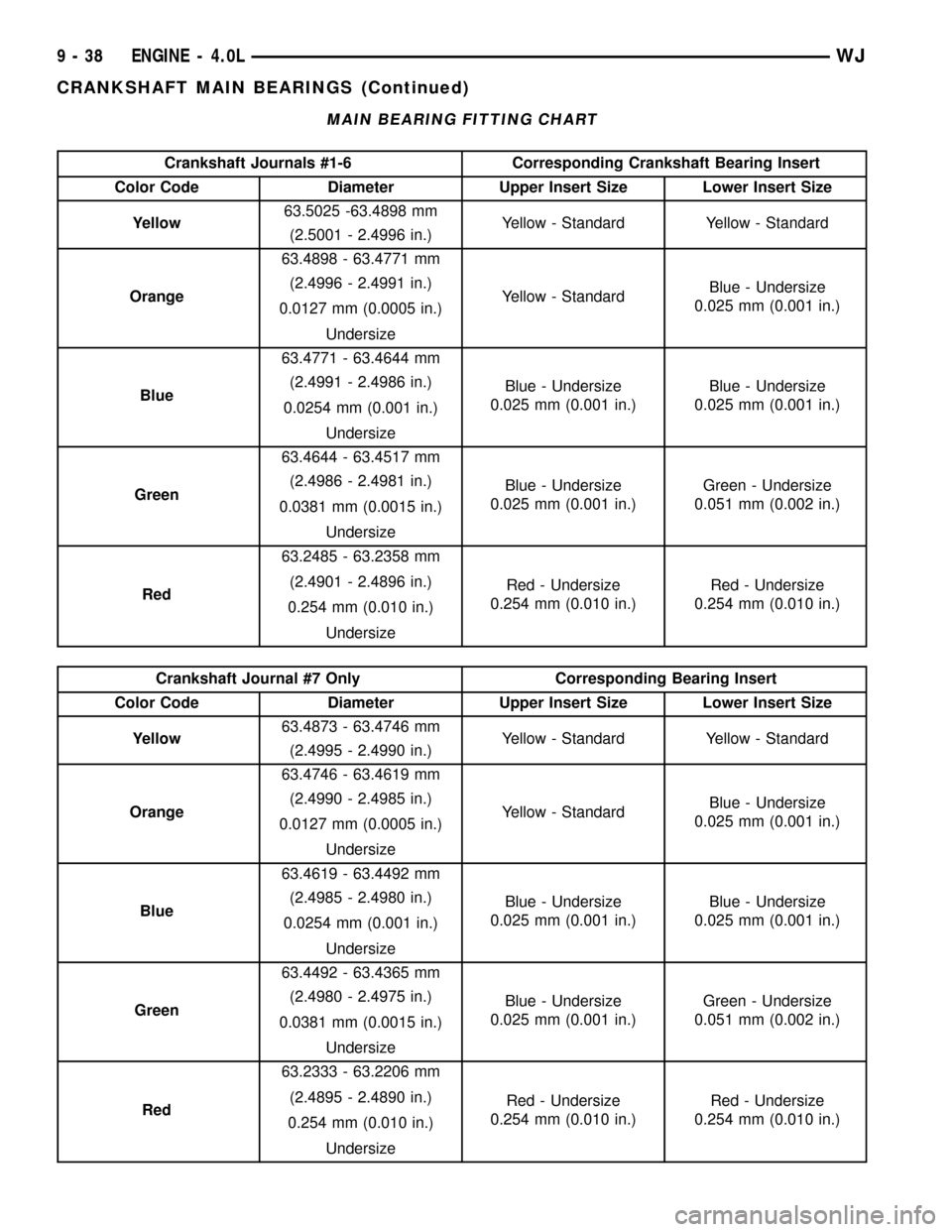
MAIN BEARING FITTING CHART
Crankshaft Journals #1-6 Corresponding Crankshaft Bearing Insert
Color Code Diameter Upper Insert Size Lower Insert Size
Yellow63.5025 -63.4898 mm
Yellow - Standard Yellow - Standard
(2.5001 - 2.4996 in.)
Orange63.4898 - 63.4771 mm
Yellow - StandardBlue - Undersize
0.025 mm (0.001 in.) (2.4996 - 2.4991 in.)
0.0127 mm (0.0005 in.)
Undersize
Blue63.4771 - 63.4644 mm
Blue - Undersize
0.025 mm (0.001 in.)Blue - Undersize
0.025 mm (0.001 in.) (2.4991 - 2.4986 in.)
0.0254 mm (0.001 in.)
Undersize
Green63.4644 - 63.4517 mm
Blue - Undersize
0.025 mm (0.001 in.)Green - Undersize
0.051 mm (0.002 in.) (2.4986 - 2.4981 in.)
0.0381 mm (0.0015 in.)
Undersize
Red63.2485 - 63.2358 mm
Red - Undersize
0.254 mm (0.010 in.)Red - Undersize
0.254 mm (0.010 in.) (2.4901 - 2.4896 in.)
0.254 mm (0.010 in.)
Undersize
Crankshaft Journal #7 Only Corresponding Bearing Insert
Color Code Diameter Upper Insert Size Lower Insert Size
Yellow63.4873 - 63.4746 mm
Yellow - Standard Yellow - Standard
(2.4995 - 2.4990 in.)
Orange63.4746 - 63.4619 mm
Yellow - StandardBlue - Undersize
0.025 mm (0.001 in.) (2.4990 - 2.4985 in.)
0.0127 mm (0.0005 in.)
Undersize
Blue63.4619 - 63.4492 mm
Blue - Undersize
0.025 mm (0.001 in.)Blue - Undersize
0.025 mm (0.001 in.) (2.4985 - 2.4980 in.)
0.0254 mm (0.001 in.)
Undersize
Green63.4492 - 63.4365 mm
Blue - Undersize
0.025 mm (0.001 in.)Green - Undersize
0.051 mm (0.002 in.) (2.4980 - 2.4975 in.)
0.0381 mm (0.0015 in.)
Undersize
Red63.2333 - 63.2206 mm
Red - Undersize
0.254 mm (0.010 in.)Red - Undersize
0.254 mm (0.010 in.) (2.4895 - 2.4890 in.)
0.254 mm (0.010 in.)
Undersize
9 - 38 ENGINE - 4.0LWJ
CRANKSHAFT MAIN BEARINGS (Continued)
Page 1282 of 2199
REMOVAL
(1) Disconnect negative cable from battery.
(2) Remove the spark plugs (Refer to 8 - ELEC-
TRICAL/IGNITION CONTROL/SPARK PLUG -
REMOVAL).
(3) Raise the vehicle.
(4) Remove the oil pan (Refer to 9 - ENGINE/LU-
BRICATION/OIL PAN - REMOVAL) and oil pump
(Refer to 9 - ENGINE/LUBRICATION/OIL PUMP -
REMOVAL).
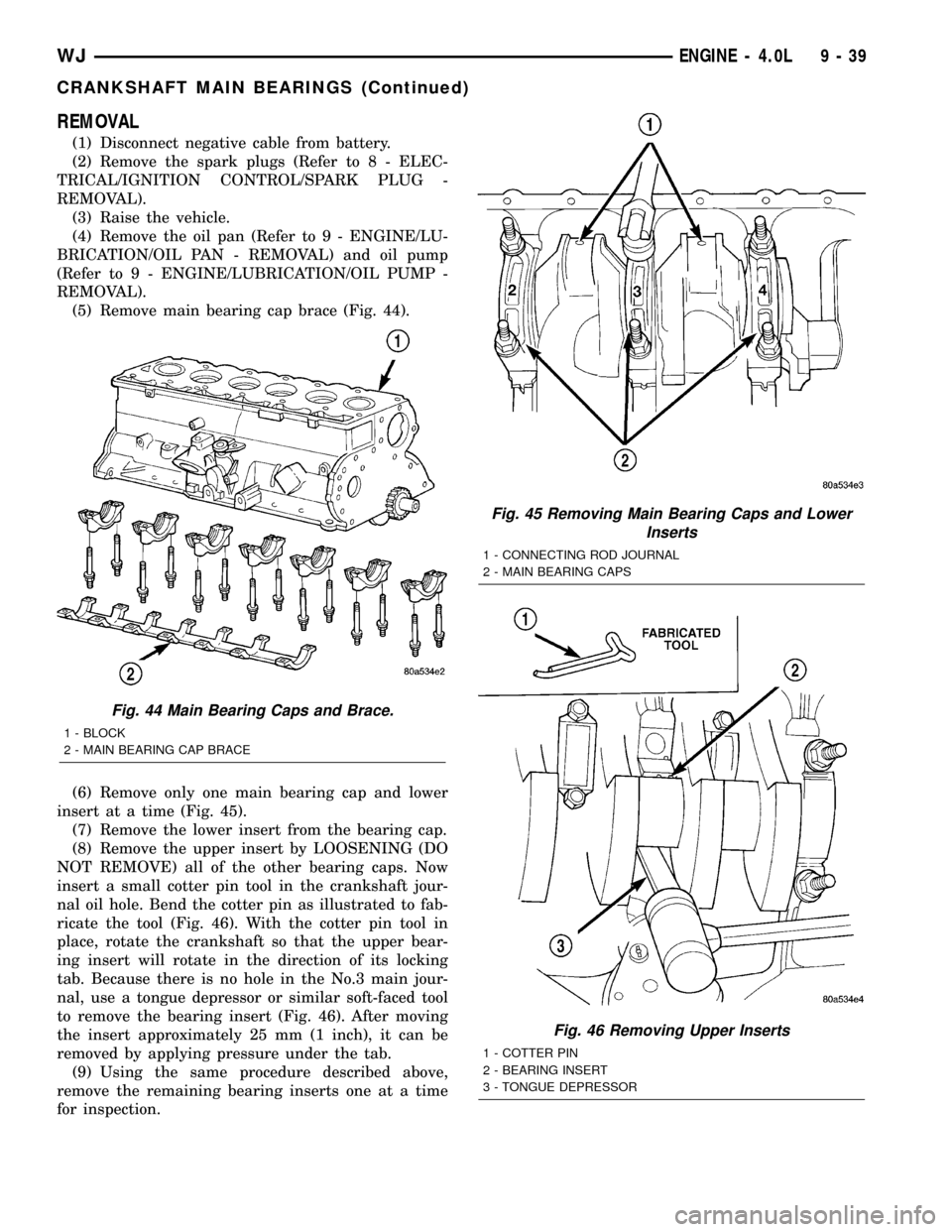
(5) Remove main bearing cap brace (Fig. 44).
(6) Remove only one main bearing cap and lower
insert at a time (Fig. 45).
(7) Remove the lower insert from the bearing cap.
(8) Remove the upper insert by LOOSENING (DO
NOT REMOVE) all of the other bearing caps. Now
insert a small cotter pin tool in the crankshaft jour-
nal oil hole. Bend the cotter pin as illustrated to fab-
ricate the tool (Fig. 46). With the cotter pin tool in
place, rotate the crankshaft so that the upper bear-
ing insert will rotate in the direction of its locking
tab. Because there is no hole in the No.3 main jour-
nal, use a tongue depressor or similar soft-faced tool
to remove the bearing insert (Fig. 46). After moving
the insert approximately 25 mm (1 inch), it can be
removed by applying pressure under the tab.
(9) Using the same procedure described above,
remove the remaining bearing inserts one at a time
for inspection.
Fig. 44 Main Bearing Caps and Brace.
1 - BLOCK
2 - MAIN BEARING CAP BRACE
Fig. 45 Removing Main Bearing Caps and Lower
Inserts
1 - CONNECTING ROD JOURNAL
2 - MAIN BEARING CAPS
Fig. 46 Removing Upper Inserts
1 - COTTER PIN
2 - BEARING INSERT
3 - TONGUE DEPRESSOR
WJENGINE - 4.0L 9 - 39
CRANKSHAFT MAIN BEARINGS (Continued)
Page 1283 of 2199
INSPECTION
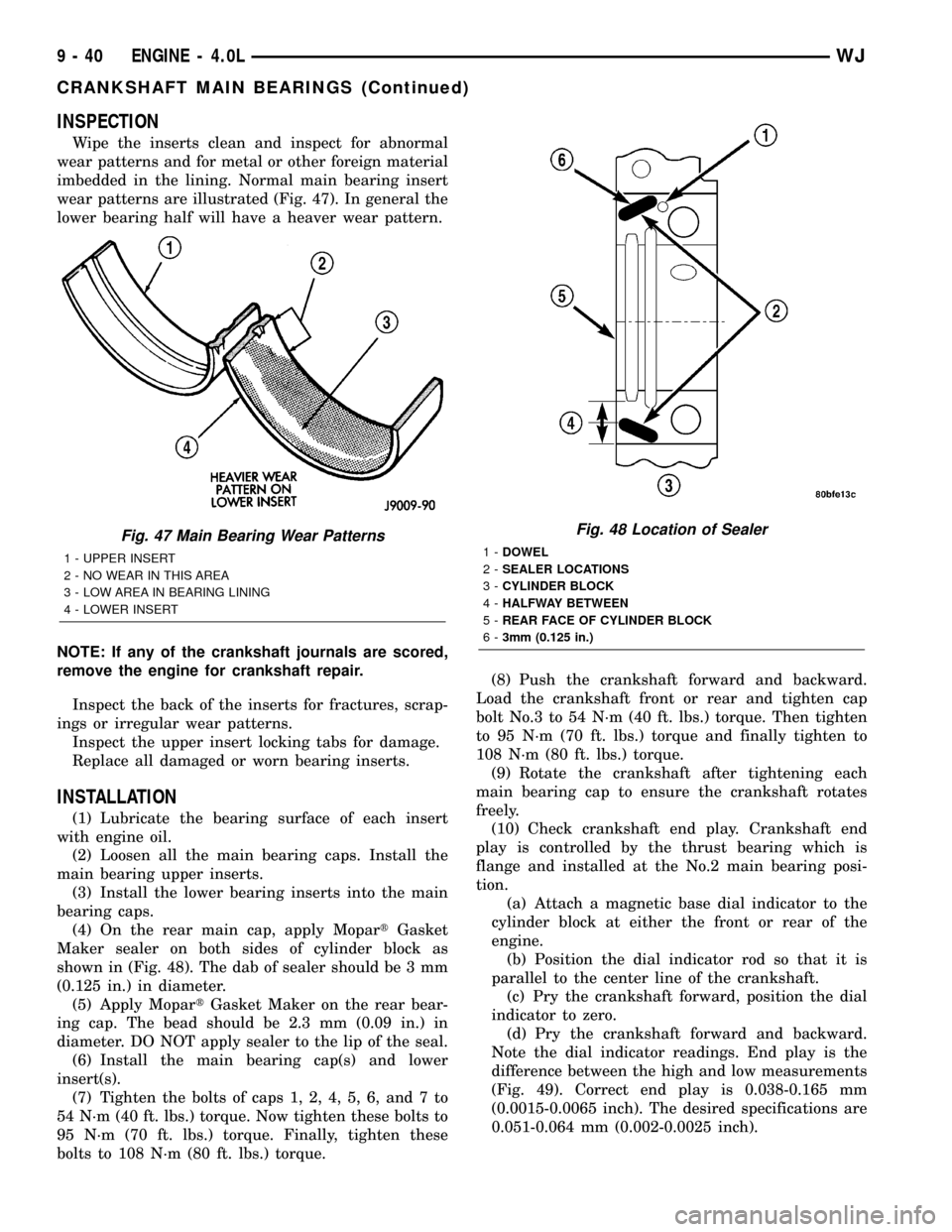
Wipe the inserts clean and inspect for abnormal
wear patterns and for metal or other foreign material
imbedded in the lining. Normal main bearing insert
wear patterns are illustrated (Fig. 47). In general the
lower bearing half will have a heaver wear pattern.
NOTE: If any of the crankshaft journals are scored,
remove the engine for crankshaft repair.
Inspect the back of the inserts for fractures, scrap-
ings or irregular wear patterns.
Inspect the upper insert locking tabs for damage.
Replace all damaged or worn bearing inserts.
INSTALLATION
(1) Lubricate the bearing surface of each insert
with engine oil.
(2) Loosen all the main bearing caps. Install the
main bearing upper inserts.
(3) Install the lower bearing inserts into the main
bearing caps.
(4) On the rear main cap, apply MopartGasket
Maker sealer on both sides of cylinder block as
shown in (Fig. 48). The dab of sealer should be 3 mm
(0.125 in.) in diameter.
(5) Apply MopartGasket Maker on the rear bear-
ing cap. The bead should be 2.3 mm (0.09 in.) in
diameter. DO NOT apply sealer to the lip of the seal.
(6) Install the main bearing cap(s) and lower
insert(s).
(7) Tighten the bolts of caps 1, 2, 4, 5, 6, and 7 to
54 N´m (40 ft. lbs.) torque. Now tighten these bolts to
95 N´m (70 ft. lbs.) torque. Finally, tighten these
bolts to 108 N´m (80 ft. lbs.) torque.(8) Push the crankshaft forward and backward.
Load the crankshaft front or rear and tighten cap
bolt No.3 to 54 N´m (40 ft. lbs.) torque. Then tighten
to 95 N´m (70 ft. lbs.) torque and finally tighten to
108 N´m (80 ft. lbs.) torque.
(9) Rotate the crankshaft after tightening each
main bearing cap to ensure the crankshaft rotates
freely.
(10) Check crankshaft end play. Crankshaft end
play is controlled by the thrust bearing which is
flange and installed at the No.2 main bearing posi-
tion.
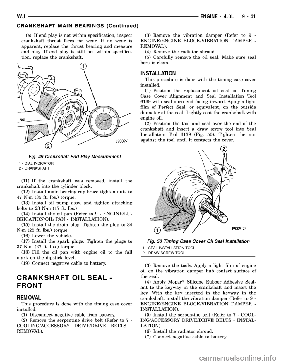
(a) Attach a magnetic base dial indicator to the
cylinder block at either the front or rear of the
engine.
(b) Position the dial indicator rod so that it is
parallel to the center line of the crankshaft.
(c) Pry the crankshaft forward, position the dial
indicator to zero.
(d) Pry the crankshaft forward and backward.
Note the dial indicator readings. End play is the
difference between the high and low measurements
(Fig. 49). Correct end play is 0.038-0.165 mm
(0.0015-0.0065 inch). The desired specifications are
0.051-0.064 mm (0.002-0.0025 inch).
Fig. 47 Main Bearing Wear Patterns
1 - UPPER INSERT
2 - NO WEAR IN THIS AREA
3 - LOW AREA IN BEARING LINING
4 - LOWER INSERT
Fig. 48 Location of Sealer
1-DOWEL
2-SEALER LOCATIONS
3-CYLINDER BLOCK
4-HALFWAY BETWEEN
5-REAR FACE OF CYLINDER BLOCK
6-3mm (0.125 in.)
9 - 40 ENGINE - 4.0LWJ
CRANKSHAFT MAIN BEARINGS (Continued)
Page 1284 of 2199
(e) If end play is not within specification, inspect
crankshaft thrust faces for wear. If no wear is
apparent, replace the thrust bearing and measure
end play. If end play is still not within specifica-
tion, replace the crankshaft.
(11) If the crankshaft was removed, install the
crankshaft into the cylinder block.
(12) Install main bearing cap brace tighten nuts to
47 N´m (35 ft. lbs.) torque.
(13) Install oil pump assy. and tighten attaching
bolts to 23 N´m (17 ft. lbs.)
(14) Install the oil pan (Refer to 9 - ENGINE/LU-
BRICATION/OIL PAN - INSTALLATION).
(15) Install the drain plug. Tighten the plug to 34
N´m (25 ft. lbs.) torque.
(16) Lower the vehicle.
(17) Install the spark plugs. Tighten the plugs to
37 N´m (27 ft. lbs.) torque.
(18) Fill the oil pan with engine oil to the full
mark on the dipstick level.
(19) Connect negative cable to battery.
CRANKSHAFT OIL SEAL -
FRONT
REMOVAL
This procedure is done with the timing case cover
installed.
(1) Disconnect negative cable from battery.
(2) Remove the serpentine drive belt (Refer to 7 -
COOLING/ACCESSORY DRIVE/DRIVE BELTS -
REMOVAL).(3) Remove the vibration damper (Refer to 9 -
ENGINE/ENGINE BLOCK/VIBRATION DAMPER -
REMOVAL).
(4) Remove the radiator shroud.
(5) Carefully remove the oil seal. Make sure seal
bore is clean.
INSTALLATION
This procedure is done with the timing case cover
installed.
(1) Position the replacement oil seal on Timing
Case Cover Alignment and Seal Installation Tool
6139 with seal open end facing inward. Apply a light
film of Perfect Seal, or equivalent, on the outside
diameter of the seal. Lightly coat the crankshaft with
engine oil.
(2) Position the tool and seal over the end of the
crankshaft and insert a draw screw tool into Seal
Installation Tool 6139 (Fig. 50). Tighten the nut
against the tool until it contacts the cover.
(3) Remove the tools. Apply a light film of engine
oil on the vibration damper hub contact surface of
the seal.
(4) Apply MopartSilicone Rubber Adhesive Seal-
ant to the keyway in the crankshaft and insert the
key. With the key inserted in the keyway in the
crankshaft, install the vibration damper (Refer to 9 -
ENGINE/ENGINE BLOCK/VIBRATION DAMPER -
INSTALLATION).
(5) Install the serpentine belt (Refer to 7 - COOL-
ING/ACCESSORY DRIVE/DRIVE BELTS - INSTAL-
LATION).
(6) Install the radiator shroud.
(7) Connect negative cable to battery.
Fig. 49 Crankshaft End Play Measurement
1 - DIAL INDICATOR
2 - CRANKSHAFT
Fig. 50 Timing Case Cover Oil Seal Installation
1 - SEAL INSTALLATION TOOL
2 - DRAW SCREW TOOL
WJENGINE - 4.0L 9 - 41
CRANKSHAFT MAIN BEARINGS (Continued)
Page 1288 of 2199
PISTON SIZE CHART
CYLINDER BORE SIZE PISTON LETTER SIZE
98.438 - 98.448 mm
(3.8755 - 3.8759 in.)A
98.448 - 98.458 mm
(3.8759 - 3.8763 in.)B
98.458 - 98.468 mm
(3.8763 - 3.8767 in.)C
98.468 - 98.478 mm
(3.8767 - 3.8771 in.)D
98.478 - 98.488 mm
(3.8771 - 3.8775 in.)E
98.488 - 98.498 mm
(3.8775 - 3.8779 in.)F
REMOVAL
(1) Remove the engine cylinder head cover. (Refer
to 9 - ENGINE/CYLINDER HEAD/CYLINDER
HEAD COVER(S) - REMOVAL).
(2) Remove the rocker arms, bridges and pivots.
(3) Remove the push rods.
(4) Remove the engine cylinder head. (Refer to 9 -
ENGINE/CYLINDER HEAD - REMOVAL).
(5) Position the pistons one at a time near the bot-
tom of the stroke. Use a ridge reamer to remove theridge from the top end of the cylinder walls. Use a
protective cloth to collect the cuttings.
(6) Raise the vehicle.
(7) Drain the engine oil.
(8) Remove the oil pan and gasket. (Refer to 9 -
ENGINE/LUBRICATION/OIL PAN - REMOVAL).
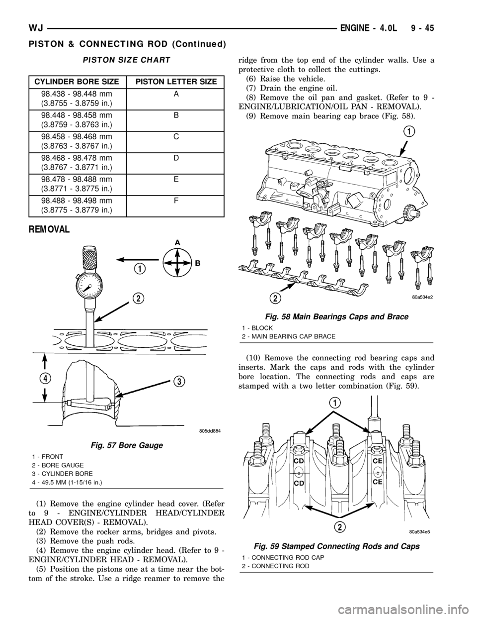
(9) Remove main bearing cap brace (Fig. 58).
(10) Remove the connecting rod bearing caps and
inserts. Mark the caps and rods with the cylinder
bore location. The connecting rods and caps are
stamped with a two letter combination (Fig. 59).
Fig. 57 Bore Gauge
1 - FRONT
2 - BORE GAUGE
3 - CYLINDER BORE
4 - 49.5 MM (1-15/16 in.)
Fig. 58 Main Bearings Caps and Brace
1 - BLOCK
2 - MAIN BEARING CAP BRACE
Fig. 59 Stamped Connecting Rods and Caps
1 - CONNECTING ROD CAP
2 - CONNECTING ROD
WJENGINE - 4.0L 9 - 45
PISTON & CONNECTING ROD (Continued)
Page 1305 of 2199
ROCKER ARM / ADJUSTER ASSEMBLY
DESCRIPTION........................107
REMOVAL............................107
INSTALLATION........................107
VALVE SPRINGS
DESCRIPTION........................108
VALVE STEM SEALS
DESCRIPTION........................108
ENGINE BLOCK
DESCRIPTION........................108
STANDARD PROCEDUREÐCYLINDER BORE
HONING...........................108
CLEANING...........................109
INSPECTION.........................109
CONNECTING ROD BEARINGS
STANDARD PROCEDURE - CONNECTING
ROD BEARING FITTING...............109
CRANKSHAFT
DESCRIPTION........................111
STANDARD PROCEDURE - MEASURING
CRANKSHAFT END PLAY..............111
REMOVAL............................112
INSPECTION..........................112
INSTALLATION........................112
CRANKSHAFT MAIN BEARINGS
STANDARD PROCEDUREÐCRANKSHAFT
MAIN BEARING - FITTING..............114
INSPECTION..........................115
CRANKSHAFT OIL SEAL - FRONT
REMOVAL............................115
INSTALLATION........................116
CRANKSHAFT OIL SEAL - REAR
REMOVAL............................117
INSTALLATION........................117
FLEX PLATE
REMOVAL............................118
INSTALLATION........................118
PISTON & CONNECTING ROD
DESCRIPTION........................118
STANDARD PROCEDUREÐPISTON FITTING . 118
REMOVAL............................118
CLEANING...........................119
INSPECTION..........................119
INSTALLATION........................120
PISTON RINGS
STANDARD PROCEDURE - PISTON RING
FITTING............................121
VIBRATION DAMPER
REMOVAL............................122
INSTALLATION........................123
STRUCTURAL COVER
DESCRIPTION........................124
OPERATION..........................124
REMOVAL............................124
INSTALLATION........................124
FRONT MOUNT
REMOVAL............................124INSTALLATION........................125
REAR MOUNT
REMOVAL............................125
INSTALLATION........................126
LUBRICATION
DESCRIPTION........................126
OPERATION..........................126
DIAGNOSIS AND TESTING
DIAGNOSIS AND TESTINGÐENGINE OIL
PRESSURE.........................128
DIAGNOSIS AND TESTINGÐREAR SEAL
AREA LEAKS........................128
DIAGNOSIS AND TESTINGÐENGINE OIL
LEAK..............................129
OIL
STANDARD PROCEDURE - ENGINE OIL....130
OIL FILTER
REMOVAL............................131
INSTALLATION........................132
OIL PAN
DESCRIPTION........................132
REMOVAL............................132
CLEANING...........................132
INSPECTION.........................132
INSTALLATION........................132
OIL PRESSURE SENSOR/SWITCH
DESCRIPTION........................133
OPERATION..........................133
REMOVAL............................133
INSTALLATION........................133
OIL PUMP
REMOVAL............................134
DISASSEMBLY........................134
CLEANING...........................134
INSPECTION.........................134
ASSEMBLY...........................135
INSTALLATION........................135
INTAKE MANIFOLD
DESCRIPTION........................136
DIAGNOSIS AND TESTINGÐINTAKE
MANIFOLD LEAKAGE.................136
REMOVAL............................136
CLEANING...........................137
INSPECTION.........................137
INSTALLATION........................137
EXHAUST MANIFOLD - LEFT
DESCRIPTION........................138
REMOVAL............................138
CLEANING...........................138
INSPECTION.........................138
INSTALLATION........................138
EXHAUST MANIFOLD - RIGHT
DESCRIPTION........................139
REMOVAL............................139
CLEANING...........................140
INSPECTION.........................141
INSTALLATION........................141
9 - 62 ENGINE - 4.7LWJ
Page 1306 of 2199
VALVE TIMING
DESCRIPTION - TIMING DRIVE SYSTEM....141
OPERATION - TIMING DRIVE SYSTEM.....141
STANDARD PROCEDURE
STANDARD PROCEDURE - ENGINE TIMING
- VERIFICATION.....................141
STANDARD PROCEDUREÐMEASURING
TIMING CHAIN WEAR.................145TIMING BELT / CHAIN COVER(S)
REMOVAL............................146
INSTALLATION........................146
TIMING BELT/CHAIN AND SPROCKETS
REMOVAL............................147
INSPECTION.........................149
INSTALLATION........................149
ENGINE - 4.7L
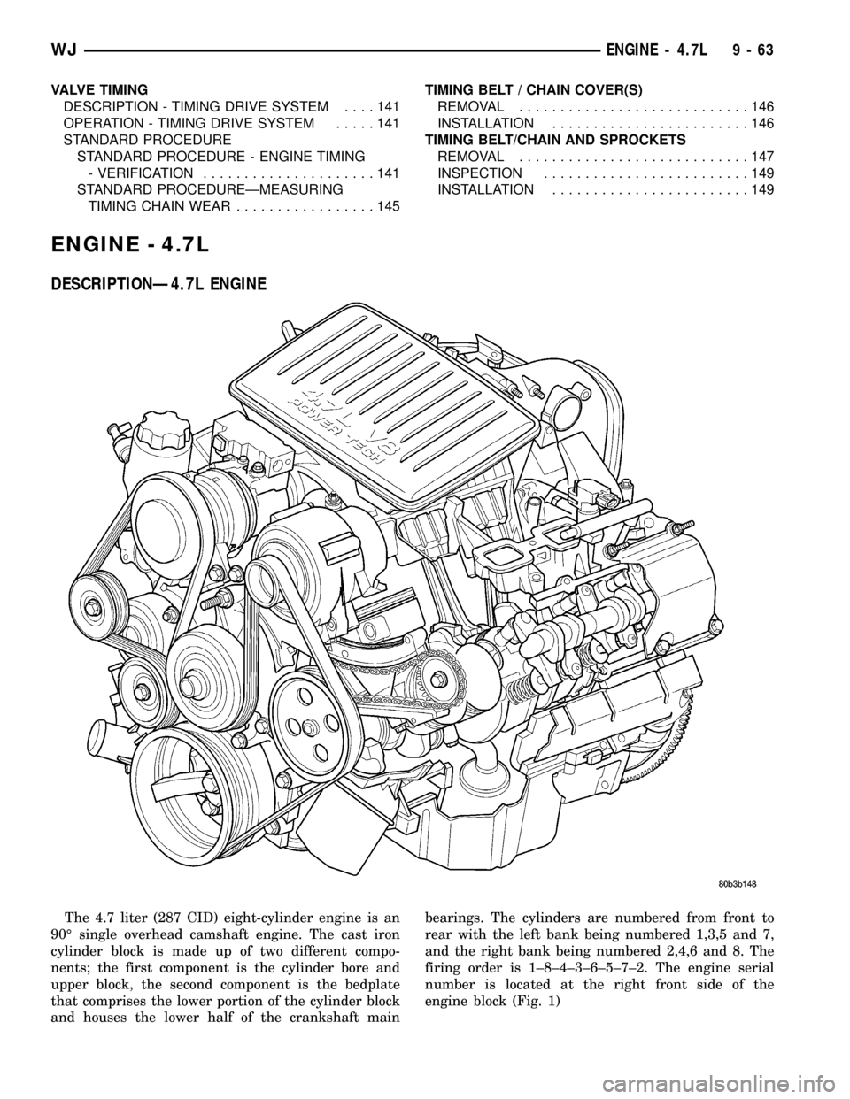
DESCRIPTIONÐ4.7L ENGINE
The 4.7 liter (287 CID) eight-cylinder engine is an
90É single overhead camshaft engine. The cast iron
cylinder block is made up of two different compo-
nents; the first component is the cylinder bore and
upper block, the second component is the bedplate
that comprises the lower portion of the cylinder block
and houses the lower half of the crankshaft mainbearings. The cylinders are numbered from front to
rear with the left bank being numbered 1,3,5 and 7,
and the right bank being numbered 2,4,6 and 8. The
firing order is 1±8±4±3±6±5±7±2. The engine serial
number is located at the right front side of the
engine block (Fig. 1)
WJENGINE - 4.7L 9 - 63