Page 1693 of 2100

7A1±6
TRANSMISSION CONTROL SYSTEM (4L30±E)
Shift Control
The transmission gear is shifted according to the shift
pattern selected by the driver. In shifting gears, the gear
ratio is controlled by the ON/ OFF signal using the shift
solenoid A and the shift solenoid B.
Band Apply Control
The band apply is controlled when in the 3±2 downshift
(engine overrun prevention) and the garage shift (shock
control).
The band apply solenoid is controlled by the signal from
the Pulse Width Modulation (PWM) to regulate the flow of
the oil.
Torque Converter Clutch Control
(Electronically Controlled Capacity Clutch
= ECCC)
The clutch apply is controlled by moving the converter
clutch valve by commanding Torque Converter Clutch
(TCC) solenoid using the PWM signal.
Line Pressure Control
The throttle signal allows the current signal to be sent to
the force motor. After receiving the current signal, the
force motor activates the pressure regulator valve to
regulate the line pressure.
On±Board Diagnostic System
Several malfunction displays can be stored in the
Powertrain Control Module (PCM) memory, and read out
of it afterward.
The serial data lines, which are required for the testing of
the final assembly and the coupling to other electronic
modules, can be regulated by this function.
Fail Safe Mechanism
If there is a problem in the transmission system, the PCM
will go into a ªbackupº mode.
The vehicle can still be driven, but the driver must use the
select lever to shift gears.
Torque Management Control
The transmission control side sends the absolute spark
advance signal to the engine control side while the
transmission is being shifted. This controls the engine
spark timing in compliance with the vehicle running
condition to reduce the shocks caused by the change of
speed.
ATF Warning Control
The oil temperature sensor detects the ATF oil
temperature to control the oil temperature warning, TCC,
and the winter mode.
Reverse Lock Out Control
With the selector lever in reverse position, the PCM will
not close the PWM solenoid until the vehicle is below 11
km/h (6.8 mph), thus preventing reverse engagement
above this speed.
Downhill Control
This mode is automatically activated from ªNORMALº
mode only when downhill conditions are recognized.
The shift pattern is identical to ªNORMALº mode except
3-4 and 4-3 shift lines at low throttle modified to get engine
braking on a larger speed range.
ECCC lines unchanged compared to ªNORMALº mode.
Uphill Control
When Uphill condition are recognized the 2-3 and 3-4 shift
and TCC apply take place only when the engine torque is
sufficient in order to avoid shift hunting.
Page 1707 of 2100

7A1±20
TRANSMISSION CONTROL SYSTEM (4L30±E)
C07RT006
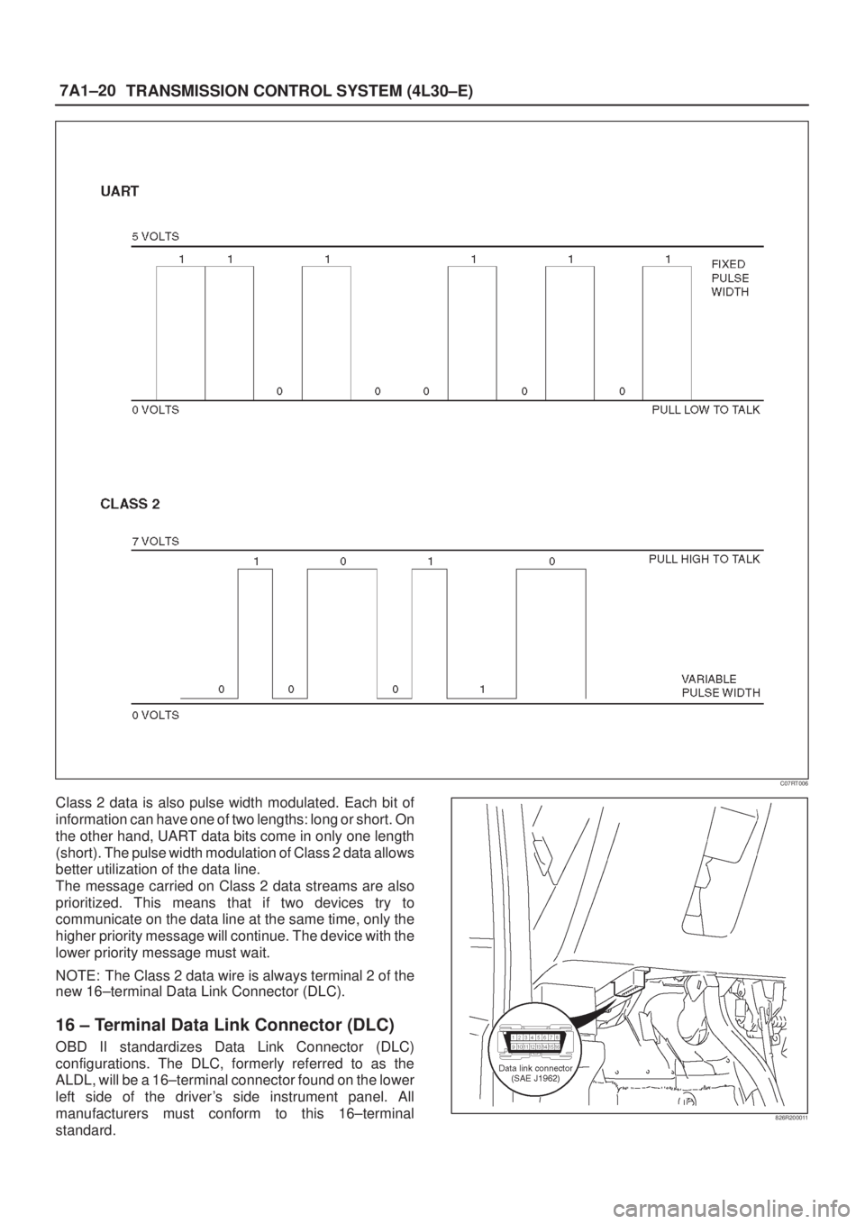
Class 2 data is also pulse width modulated. Each bit of
information can have one of two lengths: long or short. On
the other hand, UART data bits come in only one length
(short). The pulse width modulation of Class 2 data allows
better utilization of the data line.
The message carried on Class 2 data streams are also
prioritized. This means that if two devices try to
communicate on the data line at the same time, only the
higher priority message will continue. The device with the
lower priority message must wait.
NOTE: The Class 2 data wire is always terminal 2 of the
new 16±terminal Data Link Connector (DLC).
16 ± Terminal Data Link Connector (DLC)
OBD II standardizes Data Link Connector (DLC)
configurations. The DLC, formerly referred to as the
ALDL, will be a 16±terminal connector found on the lower
left side of the driver's side instrument panel. All
manufacturers must conform to this 16±terminal
standard.
826R200011
Page 1762 of 2100

TRANSMISSION CONTROL SYSTEM (4L30±E)7A1±75
DTC P1850 Brake Band Apply Solenoid Malfunction
D07R200010
Circuit Description
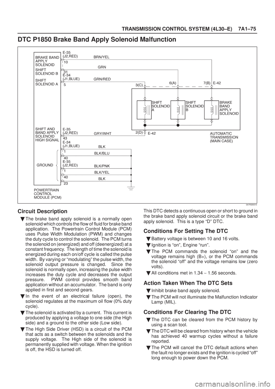
�The brake band apply solenoid is a normally open
solenoid which controls the flow of fluid for brake band
application. The Powertrain Control Module (PCM)
uses Pulse Width Modulation (PWM) and changes
the duty cycle to control the solenoid. The PCM turns
the solenoid on (energized) and off (deenergized) at a
constant frequency. The length of time the solenoid is
energized during each on/off cycle is called the pulse
width. By varying or ªmodulatingº the pulse width, the
solenoid output pressure is changed. Since the
solenoid is normally open, increasing the pulse width
increases the duty cycle and decreases the output
pressure. PWM control provides smooth band
application without an accumulator. The band is only
applied in first and second gears.
�In the event of an electrical failure (open), the
solenoid regulates at the maximum oil flow (0% duty
cycle).
�The solenoid is activated by a current. This current is
produced by applying a voltage to one side (the High
side) and a ground to the other side (Low side).
�The High Side Driver (HSD) is a circuit of the PCM
that acts as a switch between the solenoids and the
supply voltage. The High side of the solenoid is
permanently supplied with voltage. When the ignition
is off, the HSD is turned off.This DTC detects a continuous open or short to ground in
the brake band apply solenoid circuit or the brake band
apply solenoid. This is a type ªDº DTC.
Conditions For Setting The DTC
�Battery voltage is between 10 and 16 volts.
�Ignition is ªonº, Engine ªrunº.
�The PCM commands the solenoid ªonº and the
voltage remains high (B+), or the PCM commands
the solenoid ªoffº and the voltage remains low (zero
volts).
�All conditions met in 1.34 ~ 1.56 seconds.
Action Taken When The DTC Sets
�Inhibit brake band apply solenoid.
�The PCM will not illuminate the Malfunction Indicator
Lamp (MIL).
Conditions For Clearing The DTC
�The DTC can be cleared from the PCM history by
using a scan tool.
�The DTC will be cleared from history when the vehicle
has achieved 40 warmup cycles without a failure
reported.
�The PCM will cancel the DTC default actions when
the fault no longer exists and the ignition is cycled ªoffº
long enough to power down the PCM.