Page 1688 of 2100

TRANSMISSION CONTROL SYSTEM (4L30±E)7A1±1
AXIOM
TRANSMISSION
TRANSMISSION CONTROL SYSTEM (4L30±E)
CONTENTS
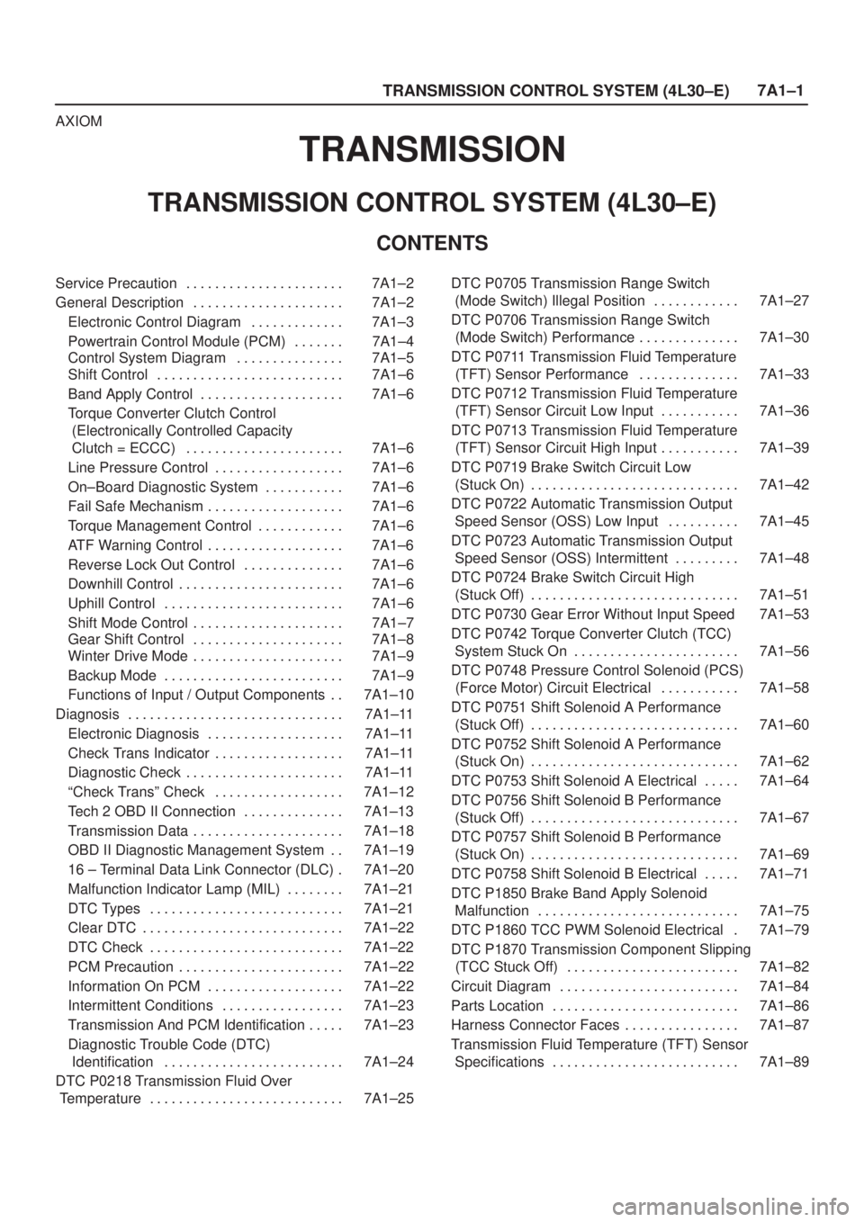
Service Precaution 7A1±2. . . . . . . . . . . . . . . . . . . . . .
General Description 7A1±2. . . . . . . . . . . . . . . . . . . . .
Electronic Control Diagram 7A1±3. . . . . . . . . . . . .
Powertrain Control Module (PCM) 7A1±4. . . . . . .
Control System Diagram 7A1±5. . . . . . . . . . . . . . .
Shift Control 7A1±6. . . . . . . . . . . . . . . . . . . . . . . . . .
Band Apply Control 7A1±6. . . . . . . . . . . . . . . . . . . .
Torque Converter Clutch Control
(Electronically Controlled Capacity
Clutch = ECCC) 7A1±6. . . . . . . . . . . . . . . . . . . . . .
Line Pressure Control 7A1±6. . . . . . . . . . . . . . . . . .
On±Board Diagnostic System 7A1±6. . . . . . . . . . .
Fail Safe Mechanism 7A1±6. . . . . . . . . . . . . . . . . . .
Torque Management Control 7A1±6. . . . . . . . . . . .
ATF Warning Control 7A1±6. . . . . . . . . . . . . . . . . . .
Reverse Lock Out Control 7A1±6. . . . . . . . . . . . . .
Downhill Control 7A1±6. . . . . . . . . . . . . . . . . . . . . . .
Uphill Control 7A1±6. . . . . . . . . . . . . . . . . . . . . . . . .
Shift Mode Control 7A1±7. . . . . . . . . . . . . . . . . . . . .
Gear Shift Control 7A1±8. . . . . . . . . . . . . . . . . . . . .
Winter Drive Mode 7A1±9. . . . . . . . . . . . . . . . . . . . .
Backup Mode 7A1±9. . . . . . . . . . . . . . . . . . . . . . . . .
Functions of Input / Output Components 7A1±10. .
Diagnosis 7A1±11. . . . . . . . . . . . . . . . . . . . . . . . . . . . . .
Electronic Diagnosis 7A1±11. . . . . . . . . . . . . . . . . . .
Check Trans Indicator 7A1±11. . . . . . . . . . . . . . . . . .
Diagnostic Check 7A1±11. . . . . . . . . . . . . . . . . . . . . .
ªCheck Transº Check 7A1±12. . . . . . . . . . . . . . . . . .
Tech 2 OBD II Connection 7A1±13. . . . . . . . . . . . . .
Transmission Data 7A1±18. . . . . . . . . . . . . . . . . . . . .
OBD II Diagnostic Management System 7A1±19. .
16 ± Terminal Data Link Connector (DLC) 7A1±20.
Malfunction Indicator Lamp (MIL) 7A1±21. . . . . . . .
DTC Types 7A1±21. . . . . . . . . . . . . . . . . . . . . . . . . . .
Clear DTC 7A1±22. . . . . . . . . . . . . . . . . . . . . . . . . . . .
DTC Check 7A1±22. . . . . . . . . . . . . . . . . . . . . . . . . . .
PCM Precaution 7A1±22. . . . . . . . . . . . . . . . . . . . . . .
Information On PCM 7A1±22. . . . . . . . . . . . . . . . . . .
Intermittent Conditions 7A1±23. . . . . . . . . . . . . . . . .
Transmission And PCM Identification 7A1±23. . . . .
Diagnostic Trouble Code (DTC)
Identification 7A1±24. . . . . . . . . . . . . . . . . . . . . . . . .
DTC P0218 Transmission Fluid Over
Temperature 7A1±25. . . . . . . . . . . . . . . . . . . . . . . . . . . DTC P0705 Transmission Range Switch
(Mode Switch) Illegal Position 7A1±27. . . . . . . . . . . .
DTC P0706 Transmission Range Switch
(Mode Switch) Performance 7A1±30. . . . . . . . . . . . . .
DTC P0711 Transmission Fluid Temperature
(TFT) Sensor Performance 7A1±33. . . . . . . . . . . . . .
DTC P0712 Transmission Fluid Temperature
(TFT) Sensor Circuit Low Input 7A1±36. . . . . . . . . . .
DTC P0713 Transmission Fluid Temperature
(TFT) Sensor Circuit High Input 7A1±39. . . . . . . . . . .
DTC P0719 Brake Switch Circuit Low
(Stuck On) 7A1±42. . . . . . . . . . . . . . . . . . . . . . . . . . . . .
DTC P0722 Automatic Transmission Output
Speed Sensor (OSS) Low Input 7A1±45. . . . . . . . . .
DTC P0723 Automatic Transmission Output
Speed Sensor (OSS) Intermittent 7A1±48. . . . . . . . .
DTC P0724 Brake Switch Circuit High
(Stuck Off) 7A1±51. . . . . . . . . . . . . . . . . . . . . . . . . . . . .
DTC P0730 Gear Error Without Input Speed 7A1±53
DTC P0742 Torque Converter Clutch (TCC)
System Stuck On 7A1±56. . . . . . . . . . . . . . . . . . . . . . .
DTC P0748 Pressure Control Solenoid (PCS)
(Force Motor) Circuit Electrical 7A1±58. . . . . . . . . . .
DTC P0751 Shift Solenoid A Performance
(Stuck Off) 7A1±60. . . . . . . . . . . . . . . . . . . . . . . . . . . . .
DTC P0752 Shift Solenoid A Performance
(Stuck On) 7A1±62. . . . . . . . . . . . . . . . . . . . . . . . . . . . .
DTC P0753 Shift Solenoid A Electrical 7A1±64. . . . .
DTC P0756 Shift Solenoid B Performance
(Stuck Off) 7A1±67. . . . . . . . . . . . . . . . . . . . . . . . . . . . .
DTC P0757 Shift Solenoid B Performance
(Stuck On) 7A1±69. . . . . . . . . . . . . . . . . . . . . . . . . . . . .
DTC P0758 Shift Solenoid B Electrical 7A1±71. . . . .
DTC P1850 Brake Band Apply Solenoid
Malfunction 7A1±75. . . . . . . . . . . . . . . . . . . . . . . . . . . .
DTC P1860 TCC PWM Solenoid Electrical 7A1±79.
DTC P1870 Transmission Component Slipping
(TCC Stuck Off) 7A1±82. . . . . . . . . . . . . . . . . . . . . . . .
Circuit Diagram 7A1±84. . . . . . . . . . . . . . . . . . . . . . . . .
Parts Location 7A1±86. . . . . . . . . . . . . . . . . . . . . . . . . .
Harness Connector Faces 7A1±87. . . . . . . . . . . . . . . .
Transmission Fluid Temperature (TFT) Sensor
Specifications 7A1±89. . . . . . . . . . . . . . . . . . . . . . . . . .
Page 1690 of 2100
TRANSMISSION CONTROL SYSTEM (4L30±E)7A1±3
Electronic Control Diagram
C07R200003
Page 1692 of 2100
TRANSMISSION CONTROL SYSTEM (4L30±E)7A1±5
Control System Diagram
C07R100005
Page 1698 of 2100

TRANSMISSION CONTROL SYSTEM (4L30±E)7A1±11
Diagnosis
Electronic Diagnosis
How To Diagnose The Problem
1. To avoid incorrect diagnostics, this book needs to be
followed accurately. Unless stated, do not jump
directly to a section that could contain the solution.
Some important information may be missed.
2. The sections in CAPITALS and bold are the main
sections that can be found in the contents.
3. The GO TO ªSECTIONº means to continue to check
going to the ªsectionº.
4. The GO THROUGH ªSECTIONº means to go
through the ªsectionº and then to go back to the place
the GO THROUGH was written.
5. BASIC ELECTRIC CIRCUITS:
You should understand the basic theory of electricity.
This includes the meaning of voltage, amps, ohms,
and what happens in a circuit with an open or shorted
wire. You should also be able to read and understand
wiring diagrams.
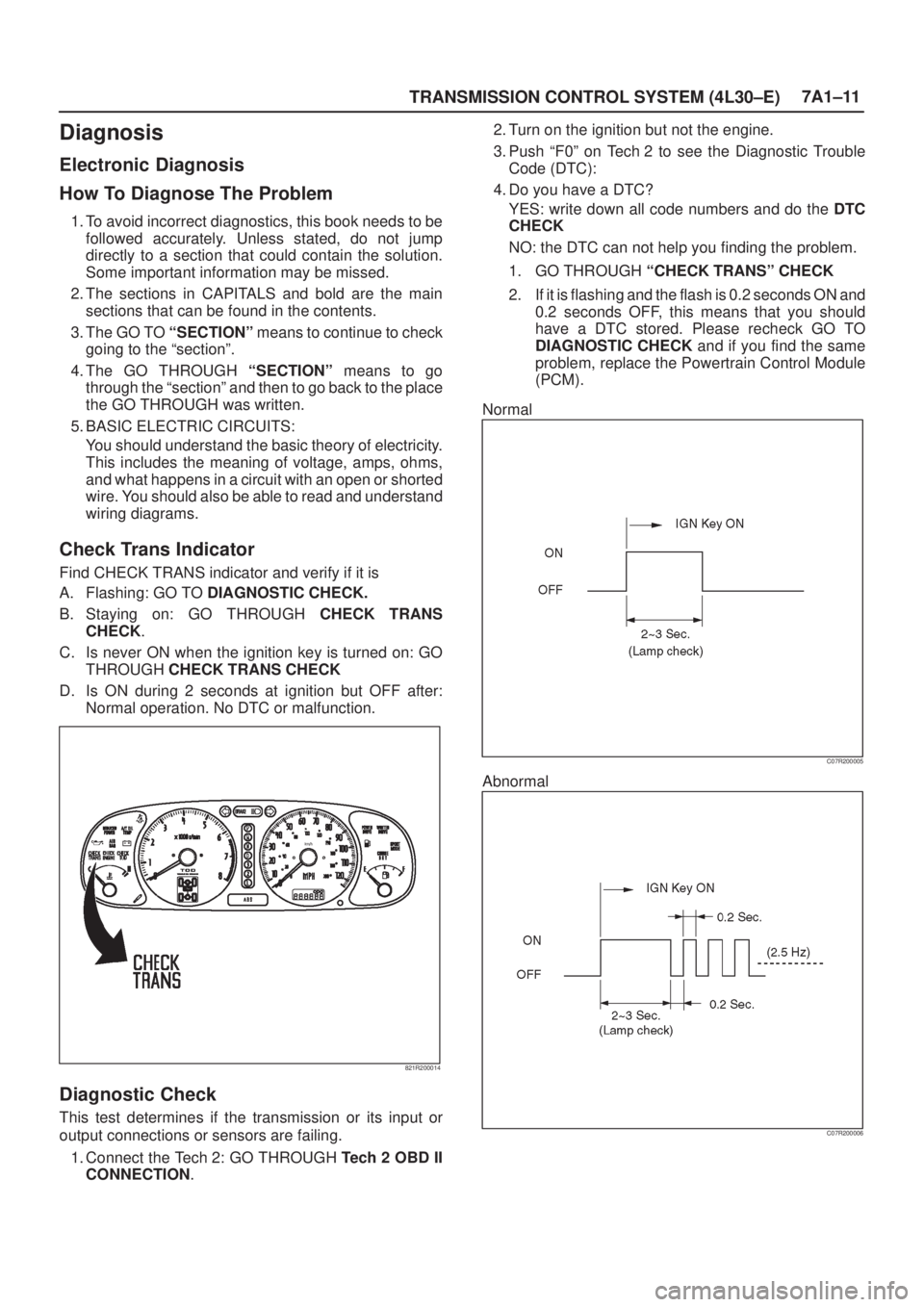
Check Trans Indicator
Find CHECK TRANS indicator and verify if it is
A. Flashing: GO TO DIAGNOSTIC CHECK.
B. Staying on: GO THROUGH CHECK TRANS
CHECK.
C. Is never ON when the ignition key is turned on: GO
THROUGH CHECK TRANS CHECK
D. Is ON during 2 seconds at ignition but OFF after:
Normal operation. No DTC or malfunction.
821R200014
Diagnostic Check
This test determines if the transmission or its input or
output connections or sensors are failing.
1. Connect the Tech 2: GO THROUGH Tech 2 OBD II
CONNECTION.2. Turn on the ignition but not the engine.
3. Push ªF0º on Tech 2 to see the Diagnostic Trouble
Code (DTC):
4. Do you have a DTC?
YES: write down all code numbers and do the DTC
CHECK
NO: the DTC can not help you finding the problem.
1. GO THROUGH ªCHECK TRANSº CHECK
2. If it is flashing and the flash is 0.2 seconds ON and
0.2 seconds OFF, this means that you should
have a DTC stored. Please recheck GO TO
DIAGNOSTIC CHECK and if you find the same
problem, replace the Powertrain Control Module
(PCM).
Normal
C07R200005
Abnormal
C07R200006
Page 1771 of 2100
7A1±84
TRANSMISSION CONTROL SYSTEM (4L30±E)
Circuit Diagram
D07R200012
Page 1836 of 2100

8D±1
WIRING SYSTEM
AXIOM
BODY AND ACCESSORIES
WIRING SYSTEM
CONTENTS
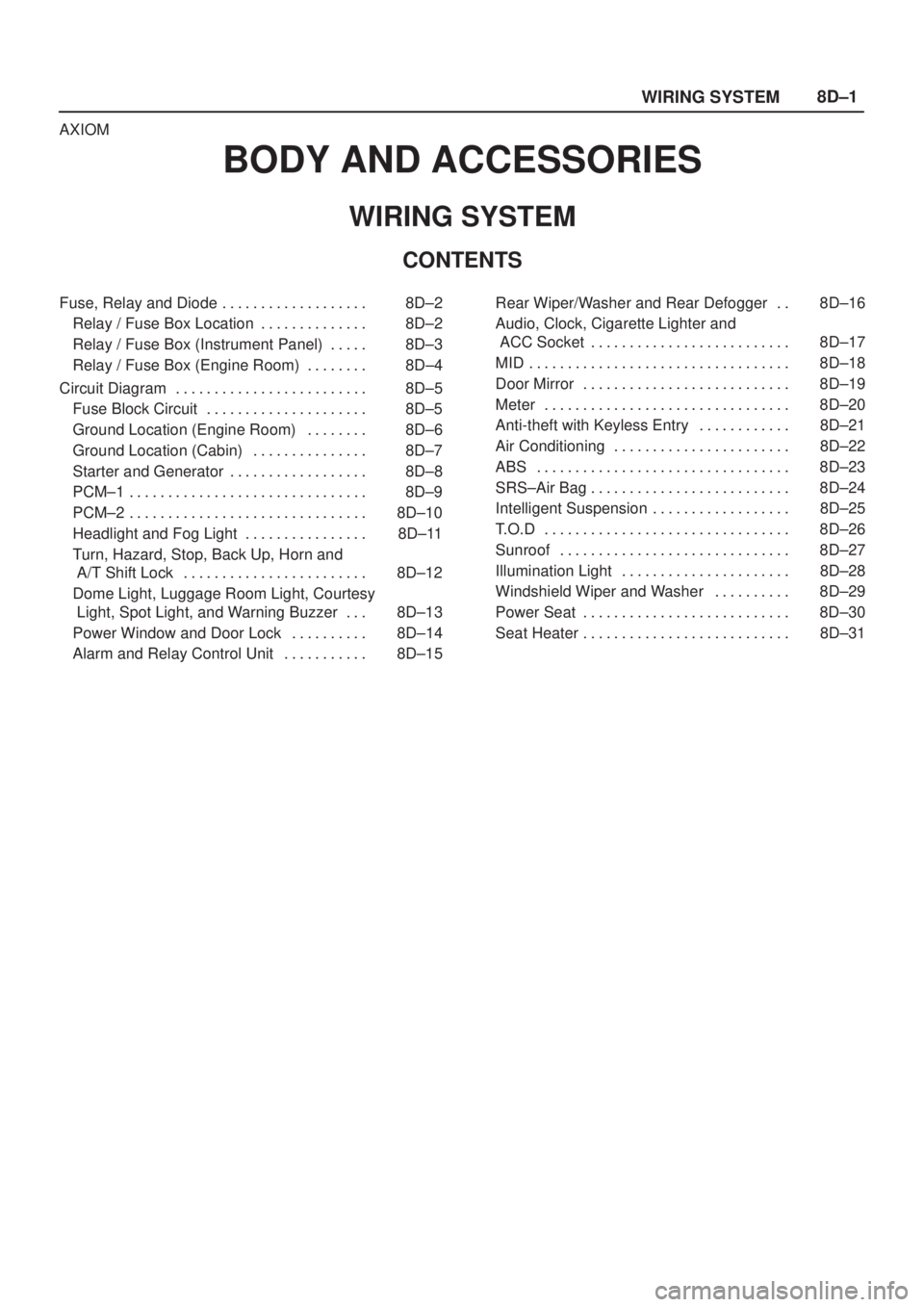
Fuse, Relay and Diode 8D±2. . . . . . . . . . . . . . . . . . .
Relay / Fuse Box Location 8D±2. . . . . . . . . . . . . .
Relay / Fuse Box (Instrument Panel) 8D±3. . . . .
Relay / Fuse Box (Engine Room) 8D±4. . . . . . . .
Circuit Diagram 8D±5. . . . . . . . . . . . . . . . . . . . . . . . .
Fuse Block Circuit 8D±5. . . . . . . . . . . . . . . . . . . . .
Ground Location (Engine Room) 8D±6. . . . . . . .
Ground Location (Cabin) 8D±7. . . . . . . . . . . . . . .
Starter and Generator 8D±8. . . . . . . . . . . . . . . . . .
PCM±1 8D±9. . . . . . . . . . . . . . . . . . . . . . . . . . . . . . .
PCM±2 8D±10. . . . . . . . . . . . . . . . . . . . . . . . . . . . . . .
Headlight and Fog Light 8D±11. . . . . . . . . . . . . . . .
Turn, Hazard, Stop, Back Up, Horn and
A/T Shift Lock 8D±12. . . . . . . . . . . . . . . . . . . . . . . .
Dome Light, Luggage Room Light, Courtesy
Light, Spot Light, and Warning Buzzer 8D±13. . .
Power Window and Door Lock 8D±14. . . . . . . . . .
Alarm and Relay Control Unit 8D±15. . . . . . . . . . . Rear Wiper/Washer and Rear Defogger 8D±16. .
Audio, Clock, Cigarette Lighter and
ACC Socket 8D±17. . . . . . . . . . . . . . . . . . . . . . . . . .
MID 8D±18. . . . . . . . . . . . . . . . . . . . . . . . . . . . . . . . . .
Door Mirror 8D±19. . . . . . . . . . . . . . . . . . . . . . . . . . .
Meter 8D±20. . . . . . . . . . . . . . . . . . . . . . . . . . . . . . . .
Anti-theft with Keyless Entry 8D±21. . . . . . . . . . . .
Air Conditioning 8D±22. . . . . . . . . . . . . . . . . . . . . . .
ABS 8D±23. . . . . . . . . . . . . . . . . . . . . . . . . . . . . . . . .
SRS±Air Bag 8D±24. . . . . . . . . . . . . . . . . . . . . . . . . .
Intelligent Suspension 8D±25. . . . . . . . . . . . . . . . . .
T.O.D 8D±26. . . . . . . . . . . . . . . . . . . . . . . . . . . . . . . .
Sunroof 8D±27. . . . . . . . . . . . . . . . . . . . . . . . . . . . . .
Illumination Light 8D±28. . . . . . . . . . . . . . . . . . . . . .
Windshield Wiper and Washer 8D±29. . . . . . . . . .
Power Seat 8D±30. . . . . . . . . . . . . . . . . . . . . . . . . . .
Seat Heater 8D±31. . . . . . . . . . . . . . . . . . . . . . . . . . .
Page 1840 of 2100
8D±5
WIRING SYSTEM
Circuit Diagram
Fuse Block Circuit
D08R200017
Page 1962 of 2100

8H±12SECURITY AND LOCKS
Key
Key Coding
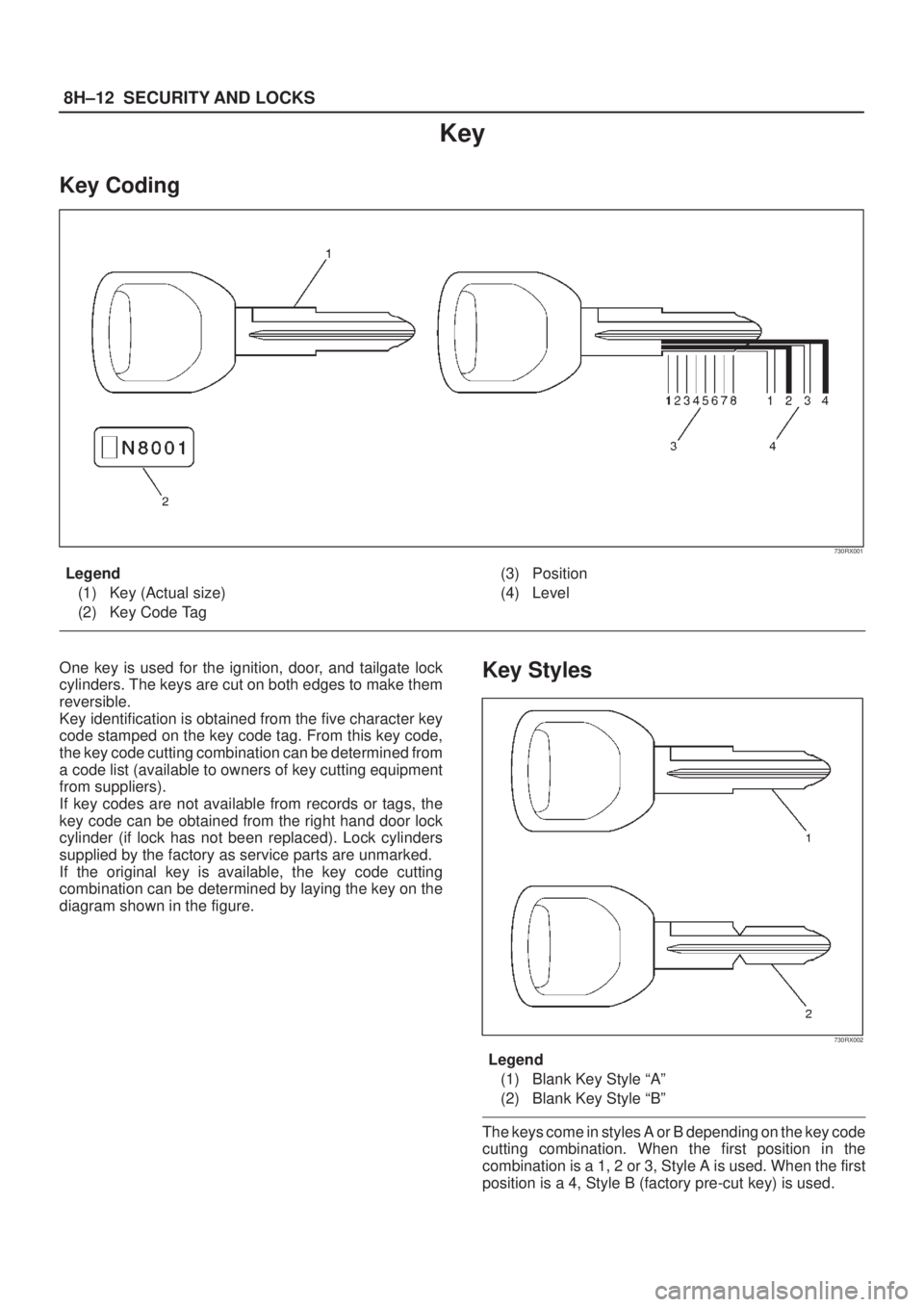
730RX001
Legend
(1) Key (Actual size)
(2) Key Code Tag(3) Position
(4) Level
One key is used for the ignition, door, and tailgate lock
cylinders. The keys are cut on both edges to make them
reversible.
Key identification is obtained from the five character key
code stamped on the key code tag. From this key code,
the key code cutting combination can be determined from
a code list (available to owners of key cutting equipment
from suppliers).
If key codes are not available from records or tags, the
key code can be obtained from the right hand door lock
cylinder (if lock has not been replaced). Lock cylinders
supplied by the factory as service parts are unmarked.
If the original key is available, the key code cutting
combination can be determined by laying the key on the
diagram shown in the figure.Key Styles
730RX002
Legend
(1) Blank Key Style ªAº
(2) Blank Key Style ªBº
The keys come in styles A or B depending on the key code
cutting combination. When the first position in the
combination is a 1, 2 or 3, Style A is used. When the first
position is a 4, Style B (factory pre-cut key) is used.