Page 1523 of 2100
6E±556
6VE1 3.5L ENGINE DRIVEABILITY AND EMISSIONS
Fuel Pump Relay
Removal Procedure
1. Remove the fuse and relay box cover from under the
hood.
2. Consult the diagram on the cover to determine which
is the correct relay.
3. Insert a small screwdriver into the catch slot on the
forward side of the fuel pump relay.
�The screwdriver blade will release the catch inside.
D08RY00291
4. Pull the relay straight up and out of the fuse and relay
box.
014RY00004
Installation Procedure
1. Insert the relay into the correct place in the fuse and
relay box with the catch slot facing forward.
2. Press down until the catch engages.
�An audible ªclickº will be heard.
014RY00004
3. Install the fuse and relay box cover.
Page 1528 of 2100

6E±561
6VE1 3.5L ENGINE DRIVEABILITY AND EMISSIONS
Catalytic Converter
Removal and Installation Procedure
Refer to Engine Exhaust in Engine section.
Air Conditioning Thermo Relay
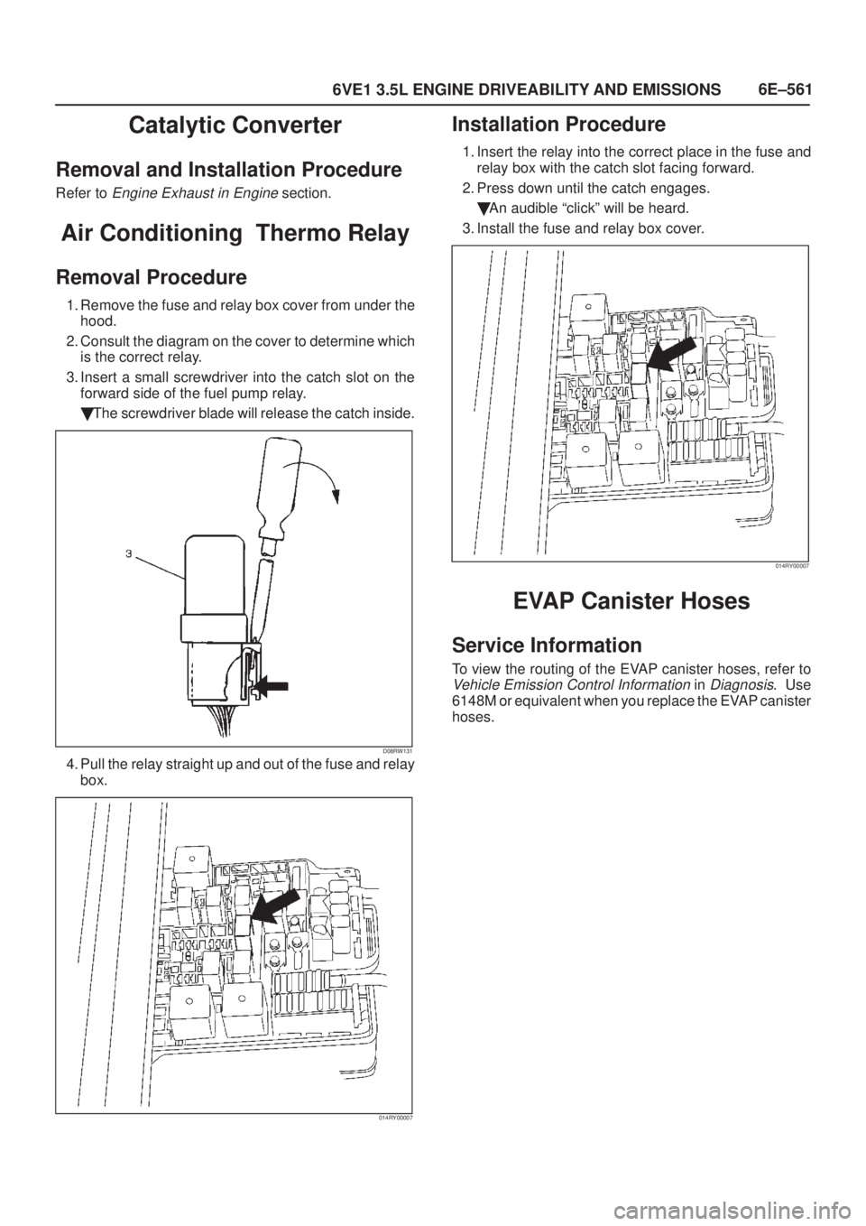
Removal Procedure
1. Remove the fuse and relay box cover from under the
hood.
2. Consult the diagram on the cover to determine which
is the correct relay.
3. Insert a small screwdriver into the catch slot on the
forward side of the fuel pump relay.
�The screwdriver blade will release the catch inside.
D08RW131
4. Pull the relay straight up and out of the fuse and relay
box.
014RY00007
Installation Procedure
1. Insert the relay into the correct place in the fuse and
relay box with the catch slot facing forward.
2. Press down until the catch engages.
�An audible ªclickº will be heard.
3. Install the fuse and relay box cover.
014RY00007
EVAP Canister Hoses
Service Information
To view the routing of the EVAP canister hoses, refer to
Vehicle Emission Control Information in Diagnosis. Use
6148M or equivalent when you replace the EVAP canister
hoses.
Page 1836 of 2100

8D±1
WIRING SYSTEM
AXIOM
BODY AND ACCESSORIES
WIRING SYSTEM
CONTENTS
Fuse, Relay and Diode 8D±2. . . . . . . . . . . . . . . . . . .
Relay / Fuse Box Location 8D±2. . . . . . . . . . . . . .
Relay / Fuse Box (Instrument Panel) 8D±3. . . . .
Relay / Fuse Box (Engine Room) 8D±4. . . . . . . .
Circuit Diagram 8D±5. . . . . . . . . . . . . . . . . . . . . . . . .
Fuse Block Circuit 8D±5. . . . . . . . . . . . . . . . . . . . .
Ground Location (Engine Room) 8D±6. . . . . . . .
Ground Location (Cabin) 8D±7. . . . . . . . . . . . . . .
Starter and Generator 8D±8. . . . . . . . . . . . . . . . . .
PCM±1 8D±9. . . . . . . . . . . . . . . . . . . . . . . . . . . . . . .
PCM±2 8D±10. . . . . . . . . . . . . . . . . . . . . . . . . . . . . . .
Headlight and Fog Light 8D±11. . . . . . . . . . . . . . . .
Turn, Hazard, Stop, Back Up, Horn and
A/T Shift Lock 8D±12. . . . . . . . . . . . . . . . . . . . . . . .
Dome Light, Luggage Room Light, Courtesy
Light, Spot Light, and Warning Buzzer 8D±13. . .
Power Window and Door Lock 8D±14. . . . . . . . . .
Alarm and Relay Control Unit 8D±15. . . . . . . . . . . Rear Wiper/Washer and Rear Defogger 8D±16. .
Audio, Clock, Cigarette Lighter and
ACC Socket 8D±17. . . . . . . . . . . . . . . . . . . . . . . . . .
MID 8D±18. . . . . . . . . . . . . . . . . . . . . . . . . . . . . . . . . .
Door Mirror 8D±19. . . . . . . . . . . . . . . . . . . . . . . . . . .
Meter 8D±20. . . . . . . . . . . . . . . . . . . . . . . . . . . . . . . .
Anti-theft with Keyless Entry 8D±21. . . . . . . . . . . .
Air Conditioning 8D±22. . . . . . . . . . . . . . . . . . . . . . .
ABS 8D±23. . . . . . . . . . . . . . . . . . . . . . . . . . . . . . . . .
SRS±Air Bag 8D±24. . . . . . . . . . . . . . . . . . . . . . . . . .
Intelligent Suspension 8D±25. . . . . . . . . . . . . . . . . .
T.O.D 8D±26. . . . . . . . . . . . . . . . . . . . . . . . . . . . . . . .
Sunroof 8D±27. . . . . . . . . . . . . . . . . . . . . . . . . . . . . .
Illumination Light 8D±28. . . . . . . . . . . . . . . . . . . . . .
Windshield Wiper and Washer 8D±29. . . . . . . . . .
Power Seat 8D±30. . . . . . . . . . . . . . . . . . . . . . . . . . .
Seat Heater 8D±31. . . . . . . . . . . . . . . . . . . . . . . . . . .
Page 1837 of 2100
8D±2
WIRING SYSTEM
Fuse, Relay and Diode
Relay / Fuse Box Location
810R200003
Legend
(1) Relay/Fuse Box (Engine Room)
(2) Relay/Fuse Box (Instrument Panel)
Page 1838 of 2100
8D±3
WIRING SYSTEM
Relay / Fuse Box (Instrument Panel)
D08RY00529
Legend
(1) Fuse/Relay Box
(2) Diode
(3) Diode
(4) Tail Relay
(5) Not Used
(6) ACC Socket Relay
(7) Power Window Relay
(8) Not Used
(9) Rear Defogger Relay
(10) Fuse ACC Socket (15A)
(11) Fuse Audio (+B) (15A)
(12) Fuse Starter (10A)
(13) Fuse Tail (15A)
(14) Fuse Room Lamp (10A)
(15) Fuse Stop Lamp (15A)
(16) Fuse Door Lock (20A)
(17) Fuse Mirror Defogger (10A)(18) Fuse Rear Defogger (15A)
(19) Fuse Rear Defogger (15A)
(20) Fuse Meter (15A)
(21) Fuse ENG. (15A)
(22) Fuse IG. Coil (15A)
(23) Fuse Back Up (15A)
(24) Fuse ELEC. IG. (15A)
(25) Fuse RR Wiper (10A)
(26) Fuse FRT Wiper (20A)
(27) Fuse Audio (ACC) (10A)
(28) Fuse Cigar Lighter (15A)
(29) Fuse Anti-theft (10A)
(30) Fuse SRS (10A)
(31) Fuse (Not Used)
(32) Circuit Breaker Power Window (30A)
(33) Spare Fuse (20A)
(34) Spare Fuse (15A)
(35) Spare Fuse (10A)
Page 1839 of 2100
8D±4
WIRING SYSTEM
Relay / Fuse Box (Engine Room)
D08R200046
Legend
(1) Fuse/Relay Box
(2) Option Box
(3) Diode (Not Used)
(4) Diode
(5) Heater Relay
(6) A/C Compressor Relay
(7) Headlamp Relay RH
(8) Not Used
(9) Fog Lamp Relay
(10) Not Used
(11) Not Used
(12) Thermo Relay
(13) Headlamp Relay LH
(14) Starter Relay
(15) ECM Main
(16) Fuel Pump Relay
(17) Not Used
(18) IG.1 (+B.1 60A)
(19) Main (100A)(20) ECM (30A)
(21) ABS (50A)
(22) IG.2 (+B.2 50A)
(23) Condenser Fan (30A)
(24) Hazard (15A)
(25) Horn (10A)
(26) ACG±S (10A)
(27) Seat Heater (15A)
(28) Blower (15A)
(29) Blower (15A)
(30) A/C (10A)
(31) Headlamp±LH (20A)
(32) Headlamp±RH (20A)
(33) Fog Lamp (15A)
(34) O
2 Sensor (20A)
(35) Fuel Pump (20A)
(36) ECM (15A)
(37) TOD (15A)
(38) Intelligent Suspension Relay (30A)
(39) Condenser Fan Relay
Page 1910 of 2100

8F±34BODY STRUCTURE
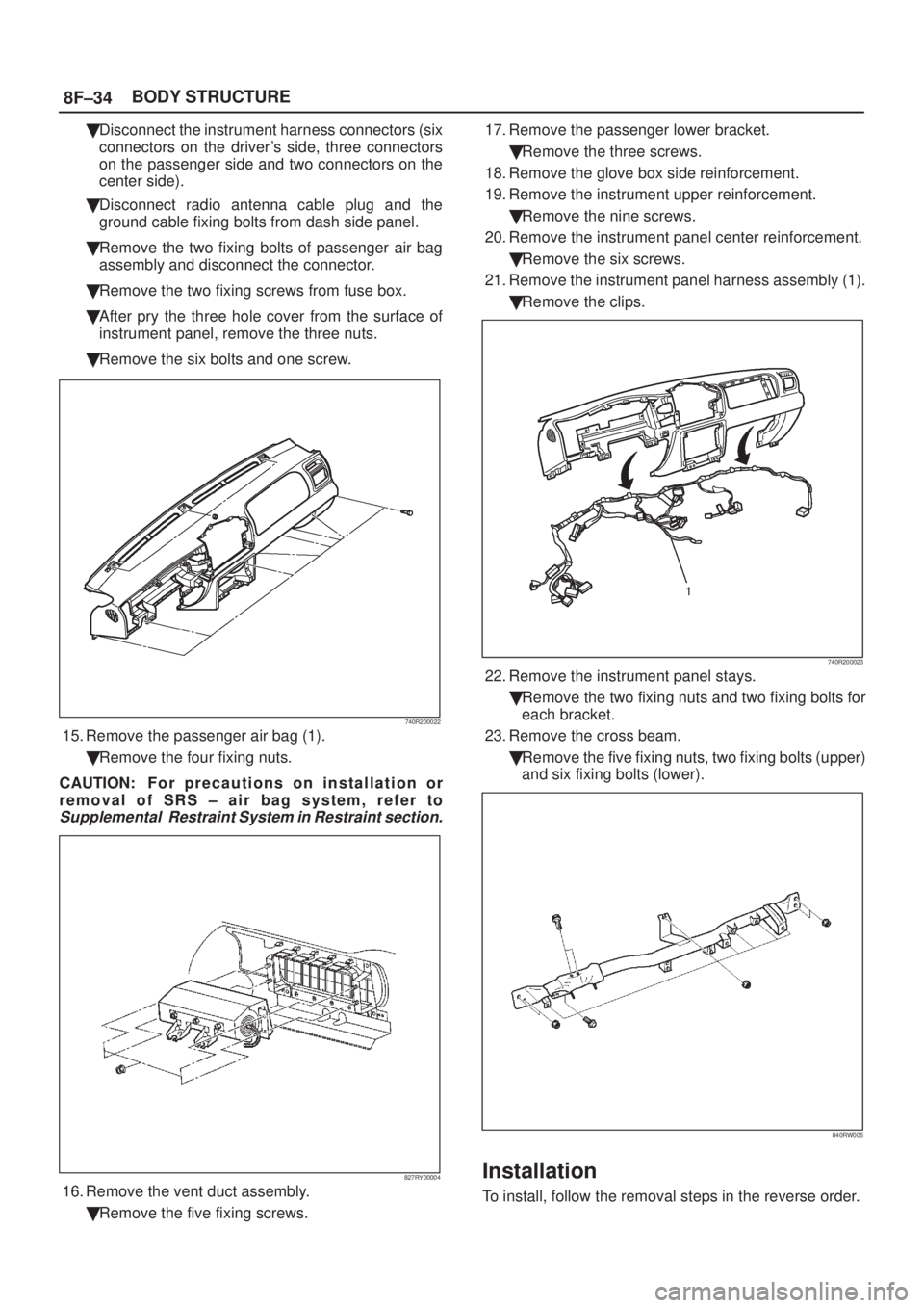
�Disconnect the instrument harness connectors (six
connectors on the driver's side, three connectors
on the passenger side and two connectors on the
center side).
�Disconnect radio antenna cable plug and the
ground cable fixing bolts from dash side panel.
�Remove the two fixing bolts of passenger air bag
assembly and disconnect the connector.
�Remove the two fixing screws from fuse box.
�After pry the three hole cover from the surface of
instrument panel, remove the three nuts.
�Remove the six bolts and one screw.
740R200022
15. Remove the passenger air bag (1).
�Remove the four fixing nuts.
CAUTION: F o r p recautions on installation or
removal of SRS ± air bag system, refer to
Supplemental Restraint System in Restraint section.
827RY00004
16. Remove the vent duct assembly.
�Remove the five fixing screws.17. Remove the passenger lower bracket.
�Remove the three screws.
18. Remove the glove box side reinforcement.
19. Remove the instrument upper reinforcement.
�Remove the nine screws.
20. Remove the instrument panel center reinforcement.
�Remove the six screws.
21. Remove the instrument panel harness assembly (1).
�Remove the clips.
740R200023
22. Remove the instrument panel stays.
�Remove the two fixing nuts and two fixing bolts for
each bracket.
23. Remove the cross beam.
�Remove the five fixing nuts, two fixing bolts (upper)
and six fixing bolts (lower).
840RW005
Installation
To install, follow the removal steps in the reverse order.
Page 2018 of 2100

SUPPLEMENTAL RESTRAINT SYSTEM 9J±4
SRS Component and Wiring Location
View
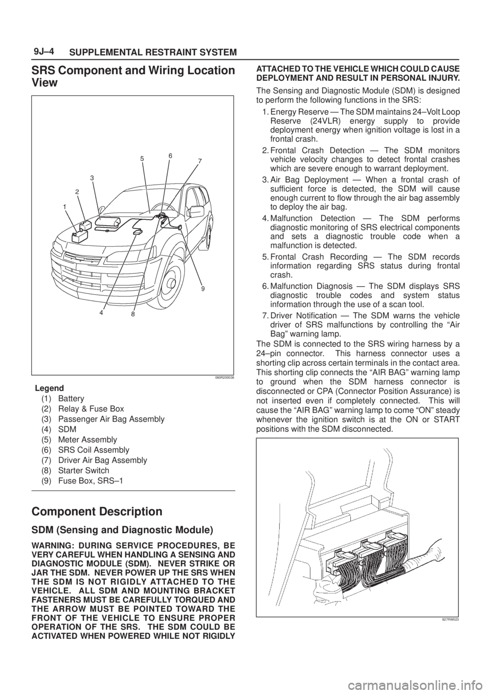
060R200036
Legend
(1) Battery
(2) Relay & Fuse Box
(3) Passenger Air Bag Assembly
(4) SDM
(5) Meter Assembly
(6) SRS Coil Assembly
(7) Driver Air Bag Assembly
(8) Starter Switch
(9) Fuse Box, SRS±1
Component Description
SDM (Sensing and Diagnostic Module)
WARNING:DURING SERVICE PROCEDURES, BE
VERY CAREFUL WHEN HANDLING A SENSING AND
DIAGNOSTIC MODULE (SDM). NEVER STRIKE OR
JAR THE SDM. NEVER POWER UP THE SRS WHEN
THE SDM IS NOT RIGIDLY ATTACHED TO THE
VEHICLE. ALL SDM AND MOUNTING BRACKET
FASTENERS MUST BE CAREFULLY TORQUED AND
THE ARROW MUST BE POINTED TOWARD THE
FRONT OF THE VEHICLE TO ENSURE PROPER
OPERATION OF THE SRS. THE SDM COULD BE
ACTIVATED WHEN POWERED WHILE NOT RIGIDLYATTACHED TO THE VEHICLE WHICH COULD CAUSE
DEPLOYMENT AND RESULT IN PERSONAL INJURY.
The Sensing and Diagnostic Module (SDM) is designed
to perform the following functions in the SRS:
1. Energy Reserve Ð The SDM maintains 24±Volt Loop
Reserve (24VLR) energy supply to provide
deployment energy when ignition voltage is lost in a
frontal crash.
2. Frontal Crash Detection Ð The SDM monitors
vehicle velocity changes to detect frontal crashes
which are severe enough to warrant deployment.
3. Air Bag Deployment Ð When a frontal crash of
sufficient force is detected, the SDM will cause
enough current to flow through the air bag assembly
to deploy the air bag.
4. Malfunction Detection Ð The SDM performs
diagnostic monitoring of SRS electrical components
and sets a diagnostic trouble code when a
malfunction is detected.
5. Frontal Crash Recording Ð The SDM records
information regarding SRS status during frontal
crash.
6. Malfunction Diagnosis Ð The SDM displays SRS
diagnostic trouble codes and system status
information through the use of a scan tool.
7. Driver Notification Ð The SDM warns the vehicle
driver of SRS malfunctions by controlling the ªAir
Bagº warning lamp.
The SDM is connected to the SRS wiring harness by a
24±pin connector. This harness connector uses a
shorting clip across certain terminals in the contact area.
This shorting clip connects the ªAIR BAGº warning lamp
to ground when the SDM harness connector is
disconnected or CPA (Connector Position Assurance) is
not inserted even if completely connected. This will
cause the ªAIR BAGº warning lamp to come ªONº steady
whenever the ignition switch is at the ON or START
positions with the SDM disconnected.
827RW023