Page 821 of 2100

6A±11
ENGINE MECHANICAL (6VE1 3.5L)
Condition CorrectionPossible cause
Engine overheatingLevel of Engine Coolant too lowReplenish
Fan clutch defectiveReplace
Incorrect fan installedReplace
Thermostat defectiveReplace
Engine Coolant pump defectiveCorrect or replace
Radiator cloggedClean or replace
Radiator filler cap defectiveReplace
Level of oil in engine crankcase too
low or wrong engine oilChange or replenish
Resistance in exhaust system
increasedClean exhaust system or replace
defective parts
Throttle Position Sensor adjustment
incorrectReplace with Throttle Valve ASM
Throttle Position Sensor circuit open
or shortedCorrect or replace
Cylinder head gasket damagedReplace
Engine overcoolingThermostat defectiveReplace (Use a thermostat set to
open at 82�C (180�F))
Engine lacks compressionÐÐÐÐRefer to Hard Start
OthersTire inflation pressure abnormalAdjust to recommended pressures
Brake dragAdjust
Clutch slippingAdjust or replace
Level of oil in engine crankcase too
highCorrect level of engine oil
Exhaust Gas Recirculation Valve
defectiveReplace
Page 825 of 2100
6A±15
ENGINE MECHANICAL (6VE1 3.5L)
Condition CorrectionPossible cause
Trouble in cylinder head partsCarbon deposits in combustion
chamberRemove carbon
Carbon deposit on valve, valve seat
and valve guideRemove carbon
Page 826 of 2100

6A±16
ENGINE MECHANICAL (6VE1 3.5L)
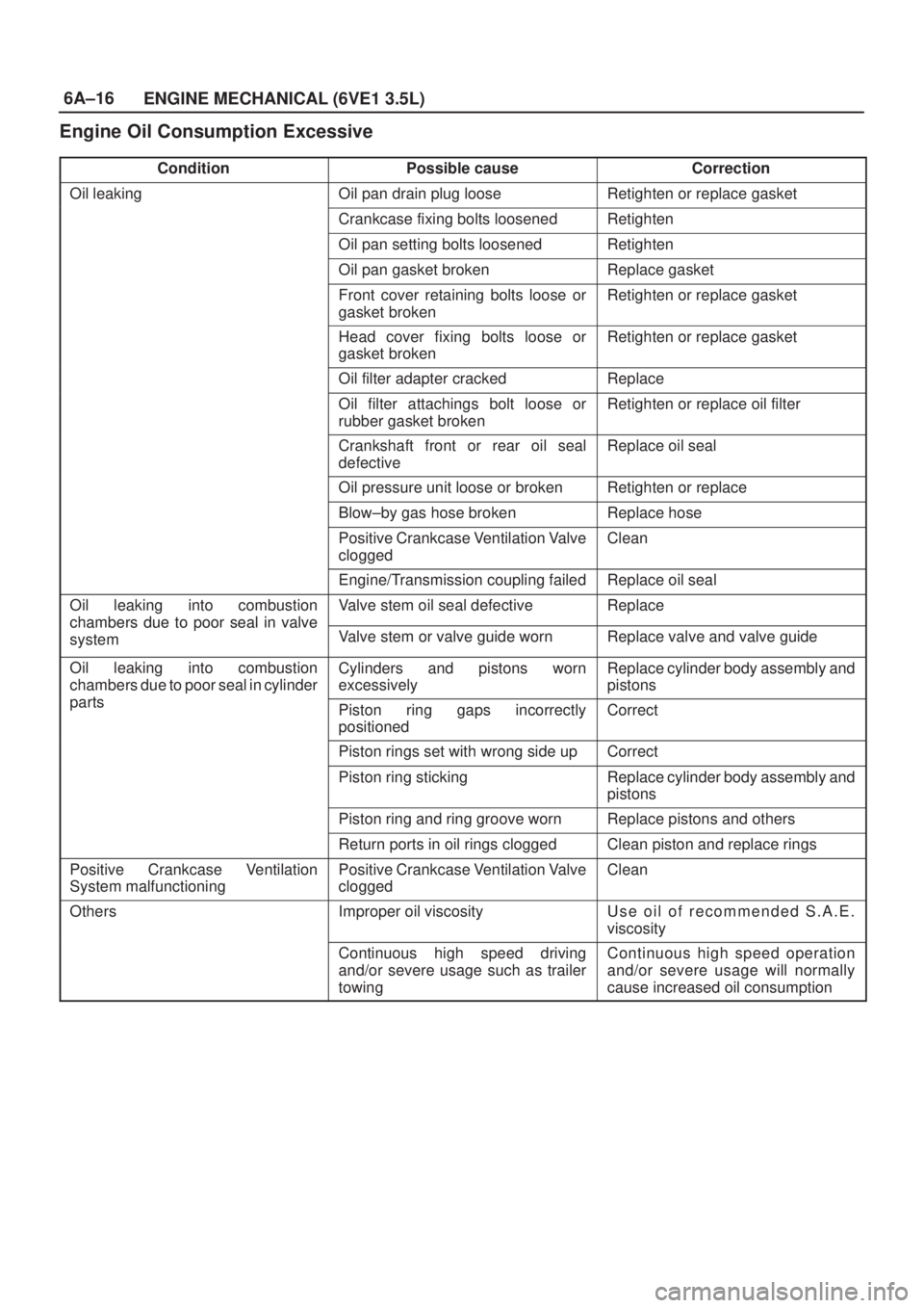
Engine Oil Consumption Excessive
ConditionPossible causeCorrection
Oil leakingOil pan drain plug looseRetighten or replace gasket
Crankcase fixing bolts loosenedRetighten
Oil pan setting bolts loosenedRetighten
Oil pan gasket brokenReplace gasket
Front cover retaining bolts loose or
gasket brokenRetighten or replace gasket
Head cover fixing bolts loose or
gasket brokenRetighten or replace gasket
Oil filter adapter crackedReplace
Oil filter attachings bolt loose or
rubber gasket brokenRetighten or replace oil filter
Crankshaft front or rear oil seal
defectiveReplace oil seal
Oil pressure unit loose or brokenRetighten or replace
Blow±by gas hose brokenReplace hose
Positive Crankcase Ventilation Valve
cloggedClean
Engine/Transmission coupling failedReplace oil seal
Oil leaking into combustion
chambers due topoor seal in valve
Valve stem oil seal defectiveReplace
chambers due to oor seal in valve
systemValve stem or valve guide wornReplace valve and valve guide
Oil leaking into combustion
chambers due to poor seal in cylinder
t
Cylinders and pistons worn
excessivelyReplace cylinder body assembly and
pistons
partsPiston ring gaps incorrectly
positionedCorrect
Piston rings set with wrong side upCorrect
Piston ring stickingReplace cylinder body assembly and
pistons
Piston ring and ring groove wornReplace pistons and others
Return ports in oil rings cloggedClean piston and replace rings
Positive Crankcase Ventilation
System malfunctioningPositive Crankcase Ventilation Valve
cloggedClean
OthersImproper oil viscosityUse oil of recommended S.A.E.
viscosity
Continuous high speed driving
and/or severe usage such as trailer
towingContinuous high speed operation
and/or severe usage will normally
cause increased oil consumption
Page 827 of 2100

6A±17
ENGINE MECHANICAL (6VE1 3.5L)
Fuel Consumption Excessive
ConditionPossible causeCorrection
Trouble in fuel systemMixture too rich or too lean due to
trouble in fuel injection systemRefer to ªAbnormal Combustionº
Fuel cut function does not workRefer to ªAbnormal Combustionº
Trouble in ignition systemMisfiring or abnormal combustion
due to trouble in ignition systemRefer to ªHard Startº or ªAbnormal
Combustionº
OthersEngine idle speed too highReset Idle Air Control Valve
Fuel system leakageCorrect or replace
Clutch slippingCorrect
Brake dragCorrect
Selection of transmission gear
incorrectCaution operator of incorrect gear
selection
Excessive Exhaust Gas
Recirculation flow due to trouble in
Exhaust Gas Recirculation systemRefer to ªAbnormal Combustionº
Lubrication Problems
ConditionPossible causeCorrection
Oil pressure too lowWrong oil in useReplace with correct engine oil
Relief valve stickingReplace
Oil pump not operating properlyCorrect or replace
Oil pump strainer cloggedClean or replace strainer
Oil pump wornReplace
Oil pressure gauge defectiveCorrect or replace
Crankshaft bearing or connecting
rod bearing wornReplace
Oil contaminationWrong oil in useReplace with correct engine oil
Oil filter cloggedReplace oil filter
Cylinder head gasket damageReplace gasket
Burned gases leakingReplace piston and piston rings or
cylinder body assembly
Oil not reaching valve systemOil passage in cylinder head or
cylinder body cloggedClean or correct
Engine Oil Pressure Check
1. Check for dirt, gasoline or water in the engine oil.
a. Check the viscosity of the oil.
b. Check the viscosity of the oil.
c. Change the oil if the viscosity is outside the
specified standard.
d. Refer to the ªMaintenance and Lubricationº section
of this manual.
2. Check the engine oil level.
The level should fall somewhere between the ªADDº
and the ªFULLº marks on the oil level dipstick.
If the oil level does not reach the ªADDº mark on the
oil level dipstick, engine oil must be added.3. Remove the oil pressure unit.
4. Install an oil pressure gauge.
5. Start the engine and allow the engine to reach normal
operating temperature (About 80�C).
6. Measure the oil pressure.
Oil pressure should be:
392±550 kPa (56.9±80.4 psi) at 3000 rpm.
7. Stop the engine.
8. Remove the oil pressure gauge.
9. Install the oil pressure unit.
10. Start the engine and check for leaks.
Page 829 of 2100
6A±19
ENGINE MECHANICAL (6VE1 3.5L)
Cylinder Head Cover LH
Removal
1. Disconnect battery ground cable.
2. Remove engine cover from the dowels on the
common chamber.
F06RY001
3. Disconnect positive crankcase ventilation hose.
4. Remove ground cable fixing bolt on cylinder head
cover.
5. Ignition coil connector and ignition coil.
�Disconnect the three connectors from the ignition
coils.
�Remove harness bracket bolt on cylinder head
cover.
�Remove fixing bolts on ignition coils.
060RY022
Legend
(1) Ignition Coil Connector
(2) Bolt
(3) Ignition Coil Assemblies
6. Disconnect fuel injector harness connector then
remove fuel injector harness bracket bolt.
7. Remove eight fixing bolts, then the cylinder head
cover.
010RW001
NOTE: Where do you refer the tech in case of bolt
removal difficulties.
Page 830 of 2100

6A±20
ENGINE MECHANICAL (6VE1 3.5L)
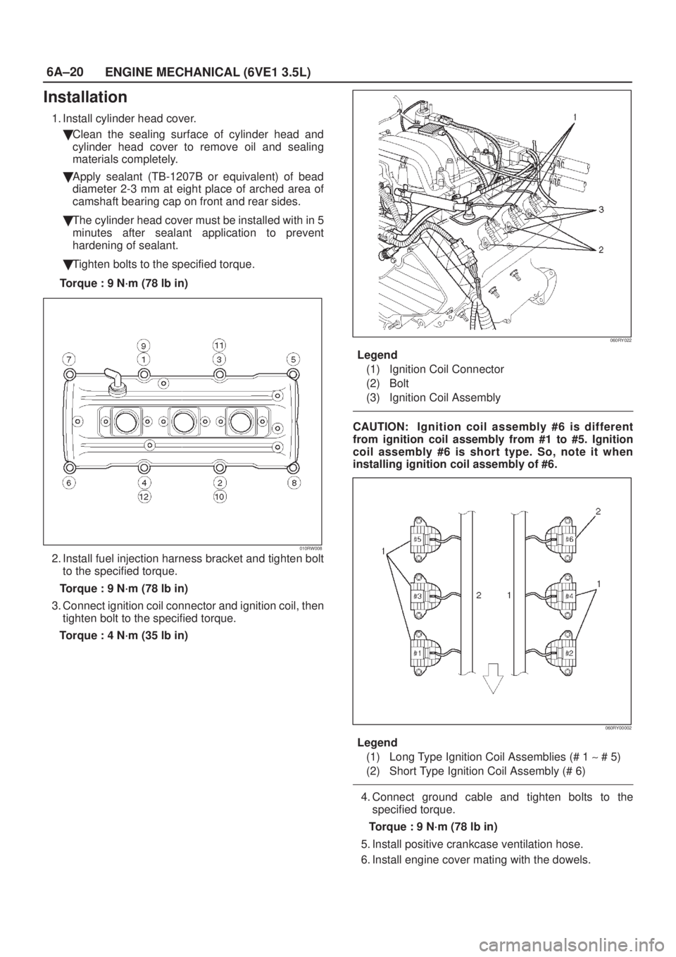
Installation
1. Install cylinder head cover.
�Clean the sealing surface of cylinder head and
cylinder head cover to remove oil and sealing
materials completely.
�Apply sealant (TB-1207B or equivalent) of bead
diameter 2-3 mm at eight place of arched area of
camshaft bearing cap on front and rear sides.
�The cylinder head cover must be installed with in 5
minutes after sealant application to prevent
hardening of sealant.
�Tighten bolts to the specified torque.
Torque : 9 N´m (78 lb in)
010RW008
2. Install fuel injection harness bracket and tighten bolt
to the specified torque.
Torque : 9 N´m (78 lb in)
3. Connect ignition coil connector and ignition coil, then
tighten bolt to the specified torque.
Torque : 4 N´m (35 lb in)
060RY022
Legend
(1) Ignition Coil Connector
(2) Bolt
(3) Ignition Coil Assembly
CAUTION: Ignition coil assembly #6 is different
from ignition coil assembly from #1 to #5. Ignition
coil assembly #6 is short type. So, note it when
installing ignition coil assembly of #6.
060RY00002
Legend
(1) Long Type Ignition Coil Assemblies (# 1 ~ # 5)
(2) Short Type Ignition Coil Assembly (# 6)
4. Connect ground cable and tighten bolts to the
specified torque.
Torque : 9 N´m (78 lb in)
5. Install positive crankcase ventilation hose.
6. Install engine cover mating with the dowels.
Page 831 of 2100

6A±21
ENGINE MECHANICAL (6VE1 3.5L)
Cylinder Head Cover RH
Removal
1. Disconnect battery ground cable.
2. Remove engine cover from the dowele on the
common chamber.
F06RY001
3. Disconnect ventilation hose from cylinder head cover.
4. Disconnect three ignition coil connectors from ignition
coils and remove harness bracket bolts on cylinder
head cover then remove ignition coil fixing bolts on
ignition coils and remove ignition coils.
5. Disconnect fuel injector harness connector then
remove fuel injector harness bracket bolt.
6. Remove eight fixing bolts then the cylinder head
cover.
010RW002
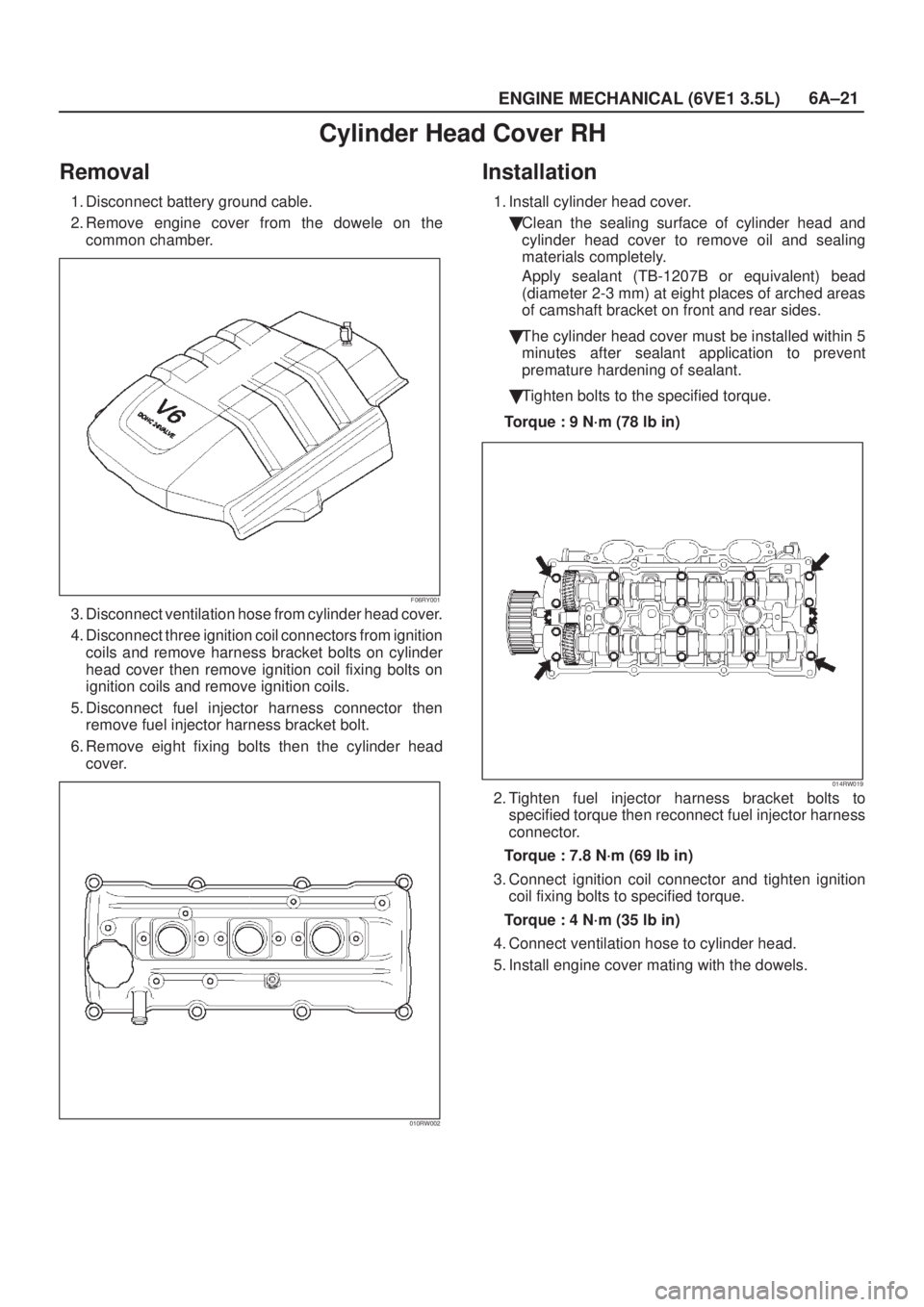
Installation
1. Install cylinder head cover.
�Clean the sealing surface of cylinder head and
cylinder head cover to remove oil and sealing
materials completely.
Apply sealant (TB-1207B or equivalent) bead
(diameter 2-3 mm) at eight places of arched areas
of camshaft bracket on front and rear sides.
�The cylinder head cover must be installed within 5
minutes after sealant application to prevent
premature hardening of sealant.
�Tighten bolts to the specified torque.
Torque : 9 N´m (78 lb in)
014RW019
2. Tighten fuel injector harness bracket bolts to
specified torque then reconnect fuel injector harness
connector.
Torque : 7.8 N´m (69 lb in)
3. Connect ignition coil connector and tighten ignition
coil fixing bolts to specified torque.
Torque : 4 N´m (35 lb in)
4. Connect ventilation hose to cylinder head.
5. Install engine cover mating with the dowels.
Page 838 of 2100

6A±28
ENGINE MECHANICAL (6VE1 3.5L)
Installation
NOTE: For correct belt installation, the letter on the belt
must be able to be read as viewed from the front of the
vehicle.
014RW005
Legend
(1) Crankshaft Timing Pulley
(2) RH Bank Camshaft Drive Gear Pulley
(3) Water Pump Pulley
(4) Idle Pulley
(5) LH Bank Camshaft Drive Gear Pulley
(6) Tension Pulley
(7) Alignment Mark on Oil Pump.
(8) Alignment Mark on Timing Belt
014RW006
Legend
(1) Timing Belt
(2) Engine Rotation Direction
(3) Cylinder Head Side
1. Install timing belt.
1. Align groove of crankshaft timing pulley (2) with
mark on oil pump (1).
Align the mark on the crankshaft timing pulley (3)
with alignment mark (white dotted line) on the tim-
ing belt (4).
Secure the belt with a double clip or equivalent
clip.
NOTE: When timing marks are aligned, No.2 piston will
be on Top Dead Center.
014RW003
Legend
(1) Alignment Mark on Oil Pump
(2) Groove on Crankshaft Timing Pulley
(3) Alignment Mark on Crankshaft Timing Pulley
(4) Alignment Mark on Timing Belt
2. Align the alignment mark on the RH bank
camshaft drive pulley (2) to the alignment mark of
the cylinder head cover RH (3).
The camshaft pulley is not 1:1 with the camshafts.
It is necessary to rotate the camshaft pulley until
the camshaft lobes are in the position as shown
in the diagram on page 6A±34.
The camshaft pulley alignment mark should also
align with alignment mark on the cylinder head
cover.
It may require up to four revolutions of the
camshaft pulley to achieve alignment of all marks.