6E±592
6VE1 3.5L ENGINE DRIVEABILITY AND EMISSIONS
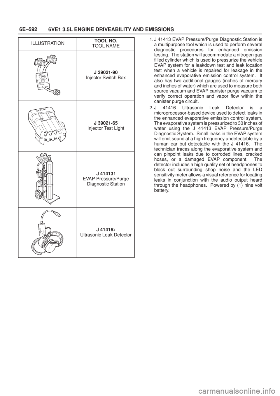
ILLUSTRATIONTOOL NO.
TOOL NAME
J 39021-90
Injector Switch Box
J 39021-65
Injector Test Light
J 41413�
EVAP Pressure/Purge
Diagnostic Station
J 41416�
Ultrasonic Leak Detector
1. J 41413 EVAP Pressure/Purge Diagnostic Station is
a multipurpose tool which is used to perform several
diagnostic procedures for enhanced emission
testing. The station will accommodate a nitrogen gas
filled cylinder which is used to pressurize the vehicle
EVAP system for a leakdown test and leak location
test when a vehicle is repaired for leakage in the
enhanced evaporative emission control system. It
also has two additional gauges (inches of mercury
and inches of water) which are used to measure both
source vacuum and EVAP canister purge vacuum to
verify correct operation and vapor flow within the
canister purge circuit.
2. J 41416 Ultrasonic Leak Detector is a
microprocessor-based device used to detect leaks in
the enhanced evaporative emission control system.
The evaporative system is pressurized to 30 inches of
water using the J 41413 EVAP Pressure/Purge
Diagnostic System. Small leaks in the EVAP system
will emit sound at a high frequency undetectable by a
human ear but detectable with the J 41416. The
technician traces along the evaporative system and
can pinpoint leaks due to corroded lines, cracked
hoses, or a damaged EVAP component. The
detector includes a high quality set of headphones to
block out surrounding shop noise and the LED
sensitivity meter allows a visual reference for locating
leaks in conjunction with the audio output heard
through the headphones. Powered by (1) nine volt
battery.
6G±2
ENGINE LUBRICATION (6VE1 3.5L)
General Description
C06RW003
Legend
(1) Oil Strainer
(2) Oil Pump
(3) Relief Valve
(4) Oil Pressure Switch
(5) Oil Filter
(6) Safety Valve
(7) Oil Gallery
(8) Crankshaft Bearing
(9) Crankshaft(10) Connecting Rod Bearing
(11) Connecting Rod
(12) Piston
(13) Oil Gallery; Cylinder Head
(14) Camshaft
(15) Camshaft Journal
(16) Front Journal; Camshaft Drive Gear
(17) Rear Journal; Camshaft Drive Gear
(18) Oil Pan
SUPPLEMENTAL RESTRAINT SYSTEM 9J±34
Steering Column
Service Precaution
WARNING: S A F E T Y P R ECAUTIONS MUST BE
FOLLOWED WHEN HANDLING A DEPLOYED AIR
BAG ASSEMBLY. AFTER DEPLOYMENT, THE AIR
BAG ASSEMBLY SURFACE MAY CONTAIN A SMALL
AMOUNT OF SODIUM HYDROXIDE, A BY±PRODUCT
OF THE DEPLOYMENT REACTION, THAT IS
IRRITATING TO THE SKIN AND EYES. MOST OF THE
POWDER ON THE AIR BAG ASSEMBLY IS
HARMLESS. AS A PRECAUTION, WEAR GLOVES
AND SAFETY GLASSES WHEN HANDLING A
DEPLOYED AIR BAG ASSEMBLY, AND WASH YOUR
HANDS WITH MILD SOAP AND WATER
AFTERWARDS.
WARNING: W H E N C A R RY I N G A L I V E A I R B A G
ASSEMBLY, MAKE SURE THE BAG AND TRIM
COVER ARE POINTED AWAY FROM YOU. NEVER
CARRY AIR BAG ASSEMBLY BY THE WIRES OR
CONNECTOR ON THE UNDERSIDE OF MODULE. IN
THE CASE OF AN ACCIDENTAL DEPLOYMENT, THE
BAG WILL THEN DEPLOY WITH MINIMAL CHANCE
OF INJURY. WHEN PLACING A LIVE AIR BAG
ASSEMBLY ON A BENCH OR OTHER SURFACE,
ALWAYS FACE BAG AND TRIM COVER UP, AWAY
FROM THE SURFACE. NEVER REST A STEERING
COLUMN ASSEMBLY ON THE STEERING WHEEL
WITH THE AIR BAG ASSEMBLY FACE DOWN AND
COLUMN VERTICAL. THIS IS NECESSARY SO THAT
A FREE SPACE IS PROVIDED TO ALLOW THE AIR
BAG ASSEMBLY TO EXPAND IN THE UNLIKELY
EVENT OF ACCIDENTAL DEPLOYMENT.
OTHERWISE, PERSONAL INJURY COULD RESULT.
NOTE: In the event deployment has occurred, inspect
coil assembly wire for any signs of scorching, melting or
any other damage due to excessive heat. If the coil has
been damaged, replace it.
Removal
1. Disable the SRS. (Refer to ªDisabling The SRSº in
this section.)
2. Remove the air bag assembly (4) from steering wheel
(2) by removing two bolts (5). Lift air bag assembly
out of steering wheel.
3. Disconnect the 2±pin yellow connector (7) and
remove air bag assembly.
4. Disconnect horn lead connector (8).
5. Remove the steering wheel attachment nut (3).
6. Move the tires to the straight ahead position before
removing the steering wheel and removing wheel with
J±29752.
7. Apply a setting mark (6) across the steering wheel
and shaft so parts can be reassembled in their
original position.
8. Feed wiring though the wheel and remove wheel.9. Remove the steering lower cover.
10. Remove the driver knee bolster assembly.
11. Remove the steering column cover (1).
12. Disconnect the wiring harness connectors (10)
located at the base of steering column.
CAUTION: Never apply force to the steering wheel
in direction of the shaft by using a hammer or other
impact tools in an attempt to remove the steering
wheel. The steering shaft is designed as an energy
absorbing unit.
13. Remove the combination switch assembly with SRS
coil (9).
NOTE: S R S c o i l i s a p a r t o f combination switch
assembly, which cannot be replaced separately.
Therefore, be sure not to remove the SRS coil from the
combination switch assembly.
14. Remove the snap ring.
15. Remove the cushion rubber.
16. Disconnect shift lock cable (A/T only)
17. Disconnect the starter switch harness connector (12)
located base of steering column.
18. Remove steering lock cylinder assembly (11).
19. Remove steering column assembly (13).
431R200004

General Description
C06RW003
Legend
(1) Oil Strainer
(2) Oil Pump
(3) Relief Valve
(4) Oil Pressure Switch
(5) Oil Filter
(6) Safety Valve
(7) Oil Gallery
(8) Cran")
