Page 1839 of 2100
8D±4
WIRING SYSTEM
Relay / Fuse Box (Engine Room)
D08R200046
Legend
(1) Fuse/Relay Box
(2) Option Box
(3) Diode (Not Used)
(4) Diode
(5) Heater Relay
(6) A/C Compressor Relay
(7) Headlamp Relay RH
(8) Not Used
(9) Fog Lamp Relay
(10) Not Used
(11) Not Used
(12) Thermo Relay
(13) Headlamp Relay LH
(14) Starter Relay
(15) ECM Main
(16) Fuel Pump Relay
(17) Not Used
(18) IG.1 (+B.1 60A)
(19) Main (100A)(20) ECM (30A)
(21) ABS (50A)
(22) IG.2 (+B.2 50A)
(23) Condenser Fan (30A)
(24) Hazard (15A)
(25) Horn (10A)
(26) ACG±S (10A)
(27) Seat Heater (15A)
(28) Blower (15A)
(29) Blower (15A)
(30) A/C (10A)
(31) Headlamp±LH (20A)
(32) Headlamp±RH (20A)
(33) Fog Lamp (15A)
(34) O
2 Sensor (20A)
(35) Fuel Pump (20A)
(36) ECM (15A)
(37) TOD (15A)
(38) Intelligent Suspension Relay (30A)
(39) Condenser Fan Relay
Page 1850 of 2100
8D±15
WIRING SYSTEM
Alarm and Relay Control Unit
D08R200024
Page 1999 of 2100

EXTERIOR/INTERIOR TRIM8J±21
Power Window System
General Description
The power window system consists of power window
switches and power window motors on driver and
passenger sides and power window relay. With the starter
switch in ªONº position, the battery voltage is supplied
through power window relay to the power window
switches on driver and passenger sides. Selection of up
or down switch changes the motor rotating direction to
open or close the window.
When the power window ªLOCKº switch on the driver side
is pressed, the power source for the other switches are
disconnected causing the power window operation to
seize.
Power Window Switch Driver Seat
Side
Removal
1. Disconnect the battery ground cable.
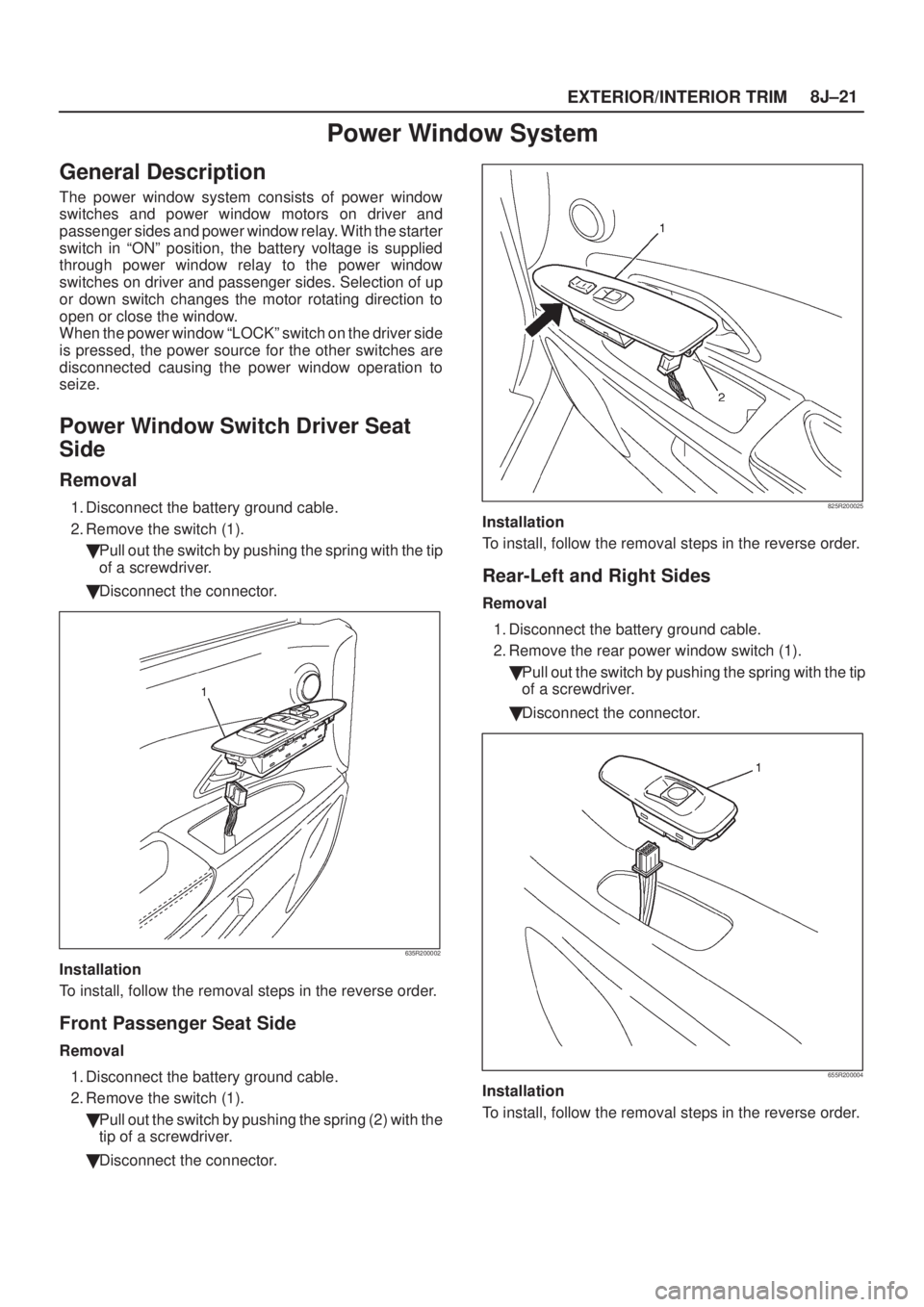
2. Remove the switch (1).
�Pull out the switch by pushing the spring with the tip
of a screwdriver.
�Disconnect the connector.
635R200002
Installation
To install, follow the removal steps in the reverse order.
Front Passenger Seat Side
Removal
1. Disconnect the battery ground cable.
2. Remove the switch (1).
�Pull out the switch by pushing the spring (2) with the
tip of a screwdriver.
�Disconnect the connector.
825R200025
Installation
To install, follow the removal steps in the reverse order.
Rear-Left and Right Sides
Removal
1. Disconnect the battery ground cable.
2. Remove the rear power window switch (1).
�Pull out the switch by pushing the spring with the tip
of a screwdriver.
�Disconnect the connector.
655R200004
Installation
To install, follow the removal steps in the reverse order.
Page 2018 of 2100

SUPPLEMENTAL RESTRAINT SYSTEM 9J±4
SRS Component and Wiring Location
View
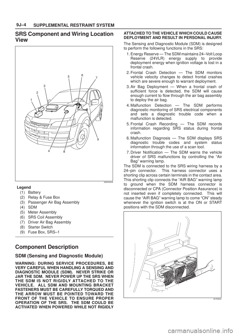
060R200036
Legend
(1) Battery
(2) Relay & Fuse Box
(3) Passenger Air Bag Assembly
(4) SDM
(5) Meter Assembly
(6) SRS Coil Assembly
(7) Driver Air Bag Assembly
(8) Starter Switch
(9) Fuse Box, SRS±1
Component Description
SDM (Sensing and Diagnostic Module)
WARNING:DURING SERVICE PROCEDURES, BE
VERY CAREFUL WHEN HANDLING A SENSING AND
DIAGNOSTIC MODULE (SDM). NEVER STRIKE OR
JAR THE SDM. NEVER POWER UP THE SRS WHEN
THE SDM IS NOT RIGIDLY ATTACHED TO THE
VEHICLE. ALL SDM AND MOUNTING BRACKET
FASTENERS MUST BE CAREFULLY TORQUED AND
THE ARROW MUST BE POINTED TOWARD THE
FRONT OF THE VEHICLE TO ENSURE PROPER
OPERATION OF THE SRS. THE SDM COULD BE
ACTIVATED WHEN POWERED WHILE NOT RIGIDLYATTACHED TO THE VEHICLE WHICH COULD CAUSE
DEPLOYMENT AND RESULT IN PERSONAL INJURY.
The Sensing and Diagnostic Module (SDM) is designed
to perform the following functions in the SRS:
1. Energy Reserve Ð The SDM maintains 24±Volt Loop
Reserve (24VLR) energy supply to provide
deployment energy when ignition voltage is lost in a
frontal crash.
2. Frontal Crash Detection Ð The SDM monitors
vehicle velocity changes to detect frontal crashes
which are severe enough to warrant deployment.
3. Air Bag Deployment Ð When a frontal crash of
sufficient force is detected, the SDM will cause
enough current to flow through the air bag assembly
to deploy the air bag.
4. Malfunction Detection Ð The SDM performs
diagnostic monitoring of SRS electrical components
and sets a diagnostic trouble code when a
malfunction is detected.
5. Frontal Crash Recording Ð The SDM records
information regarding SRS status during frontal
crash.
6. Malfunction Diagnosis Ð The SDM displays SRS
diagnostic trouble codes and system status
information through the use of a scan tool.
7. Driver Notification Ð The SDM warns the vehicle
driver of SRS malfunctions by controlling the ªAir
Bagº warning lamp.
The SDM is connected to the SRS wiring harness by a
24±pin connector. This harness connector uses a
shorting clip across certain terminals in the contact area.
This shorting clip connects the ªAIR BAGº warning lamp
to ground when the SDM harness connector is
disconnected or CPA (Connector Position Assurance) is
not inserted even if completely connected. This will
cause the ªAIR BAGº warning lamp to come ªONº steady
whenever the ignition switch is at the ON or START
positions with the SDM disconnected.
827RW023