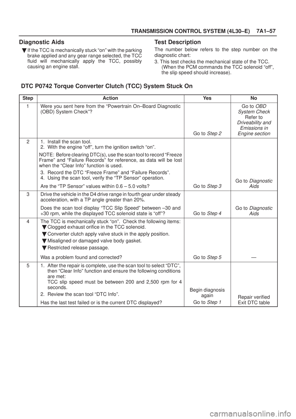
TRANSMISSION CONTROL SYSTEM (4L30±E)7A1±57
Diagnostic Aids
�If the TCC is mechanically stuck ªonº with the parking
brake applied and any gear range selected, the TCC
fluid will mechanically apply the TCC, possibly
causing an engine stall.
Test Description
The number below refers to the step number on the
diagnostic chart:
3. This test checks the mechanical state of the TCC.
(When the PCM commands the TCC solenoid ªoffº,
the slip speed should increase).
DTC P0742 Torque Converter Clutch (TCC) System Stuck On
StepActionYe sNo
1Were you sent here from the ªPowertrain On±Board Diagnostic
(OBD) System Checkº?
Go to Step 2
Go to OBD
System Check
Refer to
Driveability and
Emissions in
Engine section
21. Install the scan tool.
2. With the engine ªoffº, turn the ignition switch ªonº.
NOTE: Before clearing DTC(s), use the scan tool to record ªFreeze
Frameº and ªFailure Recordsº for reference, as data will be lost
when the ªClear Infoº function is used.
3. Record the DTC ªFreeze Frameº and ªFailure Recordsº.
4. Using the scan tool, verify the ªTP Sensorº operation.
Are the ªTP Sensorº values within 0.6 ± 5.0 volts?
Go to Step 3
Go to Diagnostic
Aids
3Drive the vehicle in the D4 drive range in fourth gear under steady
acceleration, with a TP angle greater than 20%.
Does the scan tool display ªTCC Slip Speedº between ±30 and
+30 rpm, while the displayed TCC solenoid state is ªoffº?
Go to Step 4
Go to Diagnostic
Aids
4The TCC is mechanically stuck ªonº. Check the following items:
�Clogged exhaust orifice in the TCC solenoid.
�Converter clutch apply valve stuck in the apply position.
�Misaligned or damaged valve body gasket.
�Restricted release passage.
Was a problem found and corrected?
Go to Step 5Ð
51. After the repair is complete, use the scan tool to select ªDTCº,
then ªClear Infoº function and ensure the following conditions
are met:
TCC slip speed must be between 200 and 2,500 rpm for 4
seconds.
2. Review the scan tool ªDTC Infoº.
Has the last test failed or is the current DTC displayed?
Begin diagnosis
again
Go to
Step 1
Repair verified
Exit DTC table
METER AND GAUGE8E±1
AXIOM
BODY AND ACCESSORIES
METER AND GAUGE
CONTENTS
Service Precaution 8E±1. . . . . . . . . . . . . . . . . . . . . .
General Description 8E±1. . . . . . . . . . . . . . . . . . . . .
Meter Assembly 8E±2. . . . . . . . . . . . . . . . . . . . . . . . .
General Description 8E±2. . . . . . . . . . . . . . . . . . . . .
Layout for Meters/Gauges, Warning Lights,
Indicator Lights and Illumination Lights 8E±2. . .
Table for Meter/Gauge Connector Terminal
Connections 8E±4. . . . . . . . . . . . . . . . . . . . . . . . . .
Removal 8E±6. . . . . . . . . . . . . . . . . . . . . . . . . . . . .
Installation 8E±6. . . . . . . . . . . . . . . . . . . . . . . . . . . .
Warning Light Bulb and Indicator Light Bulb 8E±6. Removal 8E±6. . . . . . . . . . . . . . . . . . . . . . . . . . . . .
Installation 8E±6. . . . . . . . . . . . . . . . . . . . . . . . . . . .
A/T Shift Indicator Light Bulb 8E±7. . . . . . . . . . . . . .
Removal 8E±7. . . . . . . . . . . . . . . . . . . . . . . . . . . . .
Installation 8E±8. . . . . . . . . . . . . . . . . . . . . . . . . . . .
Vehicle Speed Sensor 8E±9. . . . . . . . . . . . . . . . . . .
Removal 8E±9. . . . . . . . . . . . . . . . . . . . . . . . . . . . .
Installation 8E±9. . . . . . . . . . . . . . . . . . . . . . . . . . . .
Fuel Tank Unit 8E±9. . . . . . . . . . . . . . . . . . . . . . . . . .
Removal 8E±9. . . . . . . . . . . . . . . . . . . . . . . . . . . . .
Main Data and Specifications 8E±10. . . . . . . . . . . . .
Service Precaution
WARNING: THIS VEHICLE HAS A SUPPLEMENTAL
RESTRAINT SYSTEM (SRS). REFER TO THE SRS
COMPONENT AND WIRING LOCATION VIEW IN
ORDER TO DETERMINE WHETHER YOU ARE
PERFORMING SERVICE ON OR NEAR THE SRS
COMPONENTS OR THE SRS WIRING. WHEN YOU
ARE PERFORMING SERVICE ON OR NEAR THE SRS
COMPONENTS OR THE SRS WIRING, REFER TO
THE SRS SERVICE INFORMATION. FAILURE TO
FOLLOW WARNINGS COULD RESULT IN POSSIBLE
AIR BAG DEPLOYMENT, PERSONAL INJURY, OR
OTHERWISE UNNEEDED SRS SYSTEM REPAIRS.
CAUTION: Always use the correct fastener in the
proper location. When you replace a fastener, use
ONLY the exact part number for that application.
ISUZU will call out those fasteners that require a
replacement after removal. ISUZU will also call out
the fasteners that require thread lockers or thread
sealant. UNLESS OTHERWISE SPECIFIED, do not
use supplemental coatings (Paints, greases, or other
corrosion inhibitors) on threaded fasteners or
fastener joint interfaces. Generally, such coatings
adversely affect the fastener torque and the joint
clamping force, and may damage the fastener. When
you install fasteners, use the correct tightening
sequence and specifications. Following these
instructions can help you avoid damage to parts and
systems.
General Description
The circuit consists of the starter switch, meter assembly,
vehicle speed sensor, transmission switch, lighting
switch, turn signal switch, thermo unit, oil pressure unit,
Powertrain Control Module (PCM), fuel tank unit, 4WD
switch, oil pressure switch, parking brake switch, brake
fluid switch, seat belt switch, illumination controller, meter
and ambient sensor.
METER AND GAUGE8E±5
Connector A
TerminalFunction
1Ð
2Intelligent suspension indicator light
3TOD indicator light ªRearº
4Ð
5TOD indicator light ªAUTOº
6Ð
7TOD indicator light ªFrontº
8A/T shift indicator light ª3º
9A/T shift indicator light ªDº
10A/T shift indicator light ª2º
11SRS ± air bag warning light
12Ground
13Battery
14Stater switch
15A/T oil temperature warning light
16Seat belt indicator light
17Charge warning light
18Ð
19Ð
20Ð
21A/T shift indicator light ªLº
22ABS warning light
23Ð
24Ð
25Reduced power warning light
26Oil pressure warning light
27Check trans warning light
28MIL(check engine) warning light
29Check TOD
30Engine coolant temperature gauge
Connector B
TerminalFunction
1A/T shift indicator light ªRº
2A/T shift indicator light
3A/T shift indicator light ªNº
4A/T shift indicator light ªPº
5Illumination light
6Engine revolution pulse
7Speed sensor pulse
8Turn signal indicator light (LH)
9Brake warning light
10High beam indicator light (+)
11High beam indicator light (±)
12Turn signal indicator light (RH)
13Turn signal indicator light
14Ð
15Illumination light
16Ground
Connector C
TerminalFunction
1Starter switch
2Ð
3Fuel gauge
4Low fuel warning light
5Cruise set indicator light
6Ð
7Ð
8Ð
9Ð
10Sport mode indicator light
11Ð
12Winter drive indicator light
13Power drive indicator light
14Ð