Page 157 of 230
WHAT TO DO IN AN EMERGENCY 3- 7
Remove the spare tire and take out the jack and tool bag from the trunk. NOTE: The jack is located beneath the lug- gage mat in the vehicle trunk.
D060B01E-AAT 1. Obtain Spare Tire and Tool
I100A03L
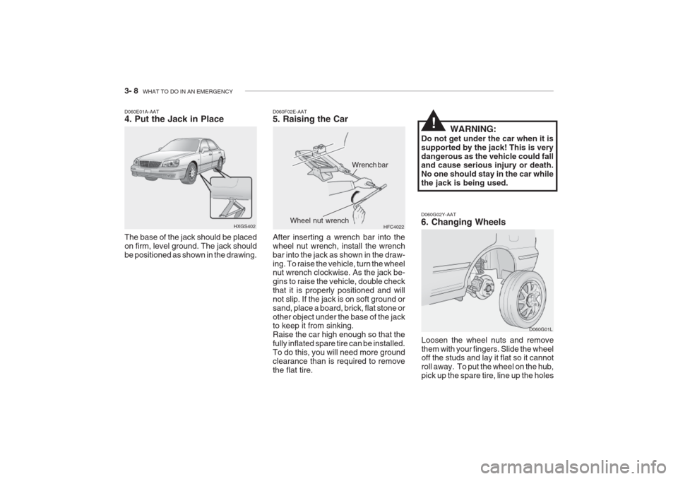
D060C01A-AAT 2. Block the Wheel Block the wheel that is diagonally op- posite from the flat to keep the vehiclefrom rolling when the car is raised onthe jack.HXG549JD060D01A-AAT 3. Loosen Wheel Nuts
HXGS413
The wheel nuts should be loosened slightly before raising the car. To loosenthe nuts, turn the wrench handle coun-terclockwise. When doing this, be sure that the socket is seated completely over the nut so it cannot slip off. Formaximum leverage, position thewrench so the handle is to the right asshown in the drawing. Then, whileholding the wrench near the end of the handle, pull up on it with steady pres- sure. Do not remove the nuts at thistime. Just loosen them about one-halfturn.
Jack
Spare tire
Flat tire
Page 158 of 230

3- 8 WHAT TO DO IN AN EMERGENCY
D060G02Y-AAT 6. Changing Wheels
Loosen the wheel nuts and remove them with your fingers. Slide the wheel off the studs and lay it flat so it cannot roll away. To put the wheel on the hub,pick up the spare tire, line up the holes D060G01L
D060F02E-AAT 5. Raising the Car After inserting a wrench bar into the wheel nut wrench, install the wrenchbar into the jack as shown in the draw-ing. To raise the vehicle, turn the wheel nut wrench clockwise. As the jack be- gins to raise the vehicle, double checkthat it is properly positioned and willnot slip. If the jack is on soft ground orsand, place a board, brick, flat stone orother object under the base of the jack to keep it from sinking. Raise the car high enough so that thefully inflated spare tire can be installed.To do this, you will need more groundclearance than is required to removethe flat tire.
HFC4022
Wrench bar
Wheel nut wrench
D060E01A-AAT 4. Put the Jack in Place The base of the jack should be placed on firm, level ground. The jack shouldbe positioned as shown in the drawing. HXGS402 WARNING:
Do not get under the car when it issupported by the jack! This is verydangerous as the vehicle could fall and cause serious injury or death. No one should stay in the car whilethe jack is being used.
!
Page 160 of 230

3- 10 WHAT TO DO IN AN EMERGENCY
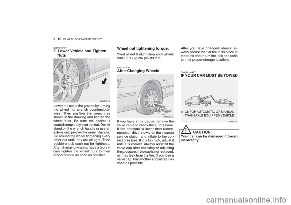
Lower the car to the ground by turning the wheel nut wrench counterclock-wise. Then position the wrench as shown in the drawing and tighten the wheel nuts. Be sure the socket isseated completely over the nut. Do notstand on the wrench handle or use anextension pipe over the wrench handle.Go around the wheel tightening every other nut until they are all tight. Then double-check each nut for tightness.After changing wheels, have a techni-cian tighten the wheel nuts to theirproper torque as soon as possible.
D060I01E-GAT 8. Lower Vehicle and Tighten
Nuts
HXGS414Wheel nut tightening torque: Steel wheel & aluminium alloy wheel: 900-1,100 kg.cm (65-80 lb.ft)
D060J01E-AAT After Changing Wheels
If you have a tire gauge, remove the valve cap and check the air pressure. If the pressure is lower than recom- mended, drive slowly to the nearestservice station and inflate to the cor-rect pressure. If it is too high, adjust ituntil it is correct. Always reinstall thevalve cap after checking or adjusting tire pressure. If the cap is not replaced, air may leak from the tire. If you lose avalve cap, buy another and install it assoon as possible. D060J01LAfter you have changed wheels, al-ways secure the flat tire in its place inthe trunk and return the jack and toolsto their proper storage locations.
D080A01A-AAT IF YOUR CAR MUST BE TOWED
CAUTION:
Your car can be damaged if towed incorrectly! o OK FOR AUTOMATIC OR MANUAL
TRANSAXLE EQUIPPED VEHICLE
D080A01L
!
Page 202 of 230

DO-IT-YOURSELF MAINTENANCE 6- 25
G290A02L-GAT
HEADLIGHT AIMING ADJUST- MENT
HID Type (If installed)
WARNING:
If you need headlight aiming ad- justment, have your vehicle in- spected by your Hyundai Dealer. Don't attempt to replace or inspect the HID headlight bulb to prevent danger of an electric shock.
Vertical Aiming HorizontalAiming
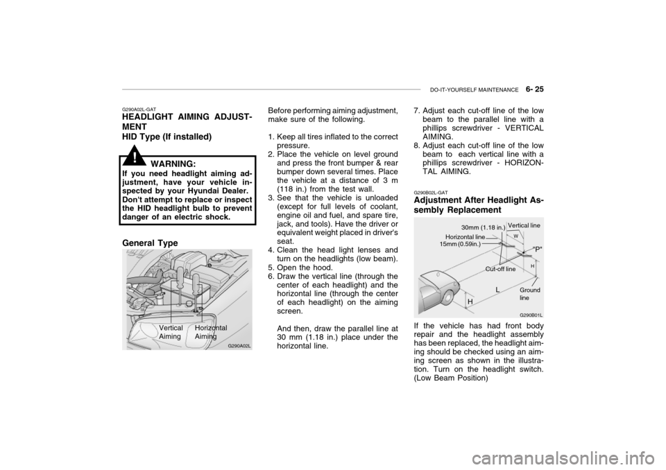
Before performing aiming adjustment, make sure of the following.
1. Keep all tires inflated to the correct pressure.
2. Place the vehicle on level ground
and press the front bumper & rear bumper down several times. Place the vehicle at a distance of 3 m (118 in.) from the test wall.
3. See that the vehicle is unloaded (except for full levels of coolant,engine oil and fuel, and spare tire,jack, and tools). Have the driver or equivalent weight placed in driver's seat.
4. Clean the head light lenses and
turn on the headlights (low beam).
5. Open the hood.
6. Draw the vertical line (through the center of each headlight) and the horizontal line (through the center of each headlight) on the aimingscreen. And then, draw the parallel line at 30 mm (1.18 in.) place under the horizontal line.
!
G290B02L-GAT
Adjustment After Headlight As- sembly Replacement
G290B01L
LW
H
H Cut-off line
Ground line
If the vehicle has had front body repair and the headlight assembly has been replaced, the headlight aim-ing should be checked using an aim- ing screen as shown in the illustra- tion. Turn on the headlight switch.(Low Beam Position)
"P"
Horizontal line15mm (0.59in.)
30mm (1.18 in.) Vertical line
7. Adjust each cut-off line of the low
beam to the parallel line with a phillips screwdriver - VERTICALAIMING.
8. Adjust each cut-off line of the low
beam to each vertical line with a phillips screwdriver - HORIZON- TAL AIMING.
G290A02L
General Type
Page 216 of 230

8. CONSUMER INFORMATION
Vehicle Identification Number (VIN) .............................................. 8-2
Engine Number .............................................................................. 8-2
Recommended Inflation Pressures ................................................ 8-2
Snow Tires ...................................................................................... 8-3
Tire Chains ..................................................................................... 8-4
Tire Rotation ................................................................................... 8-4
Tire Balancing ................................................................................. 8-4
Tire Traction ................................................................................... 8-5
When to Replace Tires .................................................................. 8-5
Spare Tire and Tools ..................................................................... 8-5
8
Page 217 of 230
8- 2 CONSUMER INFORMATION
I010B01A-AAT
Engine Number
I010A01A-GAT VEHICLE IDENTIFICATION NUM- BER (VIN) The vehicle identification number (VIN) is the number used in register-ing your car and in all legal matters pertaining to its ownership, etc. It can be found on the identification plate attached to the engine side of the firewall between the engine andpassenger compartment.
The engine number is stamped on
the engine block as shown in the drawing. I020A01A-AAT
TIRE INFORMATION
The tires supplied on your new
Hyundai are chosen to provide thebest performance for normal driving.
I030A01L-GAT
RECOMMENDED INFLATION PRESSURES
The tire label located on the driver's
door edge gives the tire pressures recommended for your car.
I010A01L
I010B02L
I030A01L
I010B01L
2.5L 3.0/3.5L
Page 218 of 230

CONSUMER INFORMATION 8- 3
CAUTION:
Always observe the following:
o Check pressures when the tires are cold. That is, after the car has been parked for at least threehours and hasn't been driven more than 1.6 km or one mile since starting up.
o Check the pressure of your spare tire each time you check thepressure of other tires.
o Never overload your car. Be es- pecially careful about overload-ing if you equip your car with a luggage rack or car top carrier. I040A01S-GAT SNOW TIRES If you equip your car with snow tires, they should be the same size and have the same load capacity as the original tires. Snow tires should beinstalled on all four wheels; other- wise, poor handling may result. Snow tires should carry 28 kPa (4 psi) more air pressure than the pres- sure recommended for the standard tires on the tire label on the driver'sdoor edge, or up to the maximum pressure shown on the tire sidewall whichever is less.Do not drive faster than 120 km/h (75mph) when your car is equipped withsnow tires.
6.0x15 6.0x16
TIRE SIZE
RIM
SIZE PRESSURE, kPa (PSI)
205/65R15 94V205/60R16 96V REAR
210(30) 210(30) FRONT
240(35) 240(35)
NORMAL LOAD MAXIMUM LOAD
REAR
240(35)240(35)
FRONT
220(32)230(33)
These pressures were chosen to pro-
vide the most satisfactory combina-tion of ride comfort, tire wear and stability under normal conditions. Tire pressures should be checked at least monthly. Proper tire inflation pressures should be maintained for these reasons:
o Lower-than-recommended tire pressures cause uneven tread wear and poor handling.
o Higher-than-recommended tire pressures increase the chance ofdamage from impacts and causeuneven tread wear.
!
Page 220 of 230

CONSUMER INFORMATION 8- 5
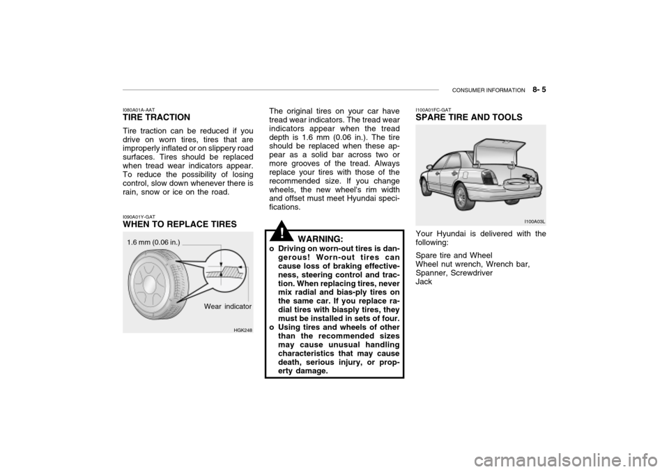
I100A01FC-GAT SPARE TIRE AND TOOLS Your Hyundai is delivered with the following: Spare tire and Wheel Wheel nut wrench, Wrench bar, Spanner, Screwdriver Jack I100A03L
The original tires on your car have tread wear indicators. The tread wear indicators appear when the treaddepth is 1.6 mm (0.06 in.). The tire should be replaced when these ap- pear as a solid bar across two ormore grooves of the tread. Always replace your tires with those of the recommended size. If you changewheels, the new wheel's rim width and offset must meet Hyundai speci- fications.
!
I080A01A-AAT
TIRE TRACTION
Tire traction can be reduced if you
drive on worn tires, tires that are improperly inflated or on slippery road surfaces. Tires should be replacedwhen tread wear indicators appear. To reduce the possibility of losing control, slow down whenever there israin, snow or ice on the road.
I090A01Y-GAT
WHEN TO REPLACE TIRES
Wear indicator
1.6 mm (0.06 in.)
HGK248WARNING:
o Driving on worn-out tires is dan- gerous! Worn-out tires can cause loss of braking effective- ness, steering control and trac-tion. When replacing tires, never mix radial and bias-ply tires on the same car. If you replace ra-dial tires with biasply tires, they must be installed in sets of four.
o Using tires and wheels of other than the recommended sizesmay cause unusual handling characteristics that may causedeath, serious injury, or prop- erty damage.