Page 50 of 140

CONTROLS AND EQUIPMENT
1- 42 SB380A1-E PARKING BRAKE The parking brake must always be set when the vehicle is to be left unattended. When the parking brake is applied, and the ignition key is at the "ON" position, the parking brake warning lamp will be illuminated. Before driving the vehicle, the parking brake must be fully released and the warning lamp extinguished.
o To set the parking brake, apply the foot brake
and pull the parking brake lever up with the button depressed. Release the button when the brake is fully applied.
o To release the parking brake, apply the foot
brake and pull up the parking brake lever slightly. Depress the button and lower the lever.
SB370A1-E INTERIOR REAR VIEW MIRROR The interior mirror is of the day/night type to enable the glare of headlamps from following vehicles to be eliminated during night time driv- ing. The tab located at the bottom of the mirror should be set to the position nearest the windscreen for normal day time driving, and flipped towards the rear of the vehicle to eliminate glare during night time driving. To adjust the field of vision, the mirror may be moved by hand upon the mount- ing. NOTE: The mirror should always be adjusted prior to setting the vehicle in motion.
B520A01GK
B520B01O-GAT DAY/NIGHT REAR VIEW MIRROR (Electric type) (Not all models) The electric type day/night inside rearview mirror automatically controls the glare of headlights of the car behind you. Adjust the rearview mirror to the desired position.
B520B01GK
Sensor
HGK178
Page 65 of 140

CONTROLS AND EQUIPMENT1- 57
B970C02E-AAT Automatic Operation
HGK020
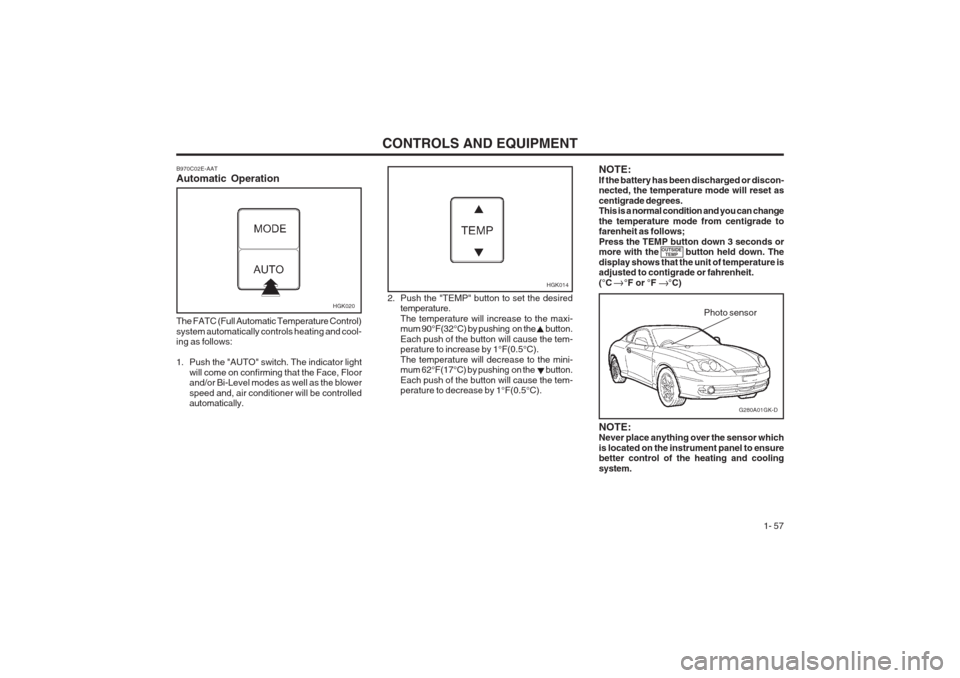
The FATC (Full Automatic Temperature Control) system automatically controls heating and cool- ing as follows:
1. Push the "AUTO" switch. The indicator light will come on confirming that the Face, Floor and/or Bi-Level modes as well as the blower speed and, air conditioner will be controlled automatically. 2. Push the "TEMP" button to set the desired
temperature. The temperature will increase to the maxi- mum 90°F(32°C) by pushing on the button. Each push of the button will cause the tem- perature to increase by 1°F(0.5°C). The temperature will decrease to the mini- mum 62°F(17°C) by pushing on the button. Each push of the button will cause the tem- perature to decrease by 1°F(0.5°C).
G280A01GK-D
Photo sensor
HGK014
NOTE: Never place anything over the sensor which is located on the instrument panel to ensure better control of the heating and cooling system.
NOTE:If the battery has been discharged or discon- nected, the temperature mode will reset as centigrade degrees. This is a normal condition and you can change the temperature mode from centigrade to farenheit as follows; Press the TEMP button down 3 seconds or more with the button held down. The display shows that the unit of temperature is adjusted to contigrade or fahrenheit. (°C °F or °F °C)
OUTSIDE
TEMP
Page 114 of 140

OWNER MAINTENANCE 6-9
SG070A1-E AIR CLEANER ELEMENT REPLACE- MENT
Prior to installing a sparking plug, the gap be- tween the centre and outer electrodes must be checked and adjusted as necessary. Adjustment is facilitated by bending the outer electrode towards or away from the centre elec- trode. Under no circumstances should attempts be made to adjust the position of the centre electrode.
4. Insert the sparking plug into the cylinder head and screw by the wrench and until the plug contacts the seating area. Tighten the plug with the socket by a further 1/2 to 3/4 of a turn only. 5. Replace the plug lead ensuring that the cap is
pushed firmly into place. Confirm that the capis correctly seated by lightly pulling upon it.
Recommended Spark Plugs To replace the air cleaner element, remove theair intake ducting from the air flow sensor body and unfasten the spring clips holding the air flow sensor top to the body. Lift out the air flow sensor followed by the air cleaner element. Replace- ment of the element is the reverse of the above. CAUTION: The air flow sensor is a precision engineered electronic measuring device and therefore care should be exercised that the air flow sensor is not damaged during replacement of the element. To ensure maximum filtration performance and continued engine performance, only genuine Hyundai replacements should be used.
NOTE:When replacing the spark plug, always use the genuine parts recommended.
RC10YC4(CHAMPION) BKR5ES-11(NGK) RC10PYPB4(CHAMPION) PFR5N-11(NGK)1.6/2.0L
2.7L*
* Platimun coated.
HGK213
HGK258HGK257
Page 127 of 140
OWNER MAINTENANCE
6-22
G200C01GK-GAT FUSE PANEL DESCRIPTION Engine Compartment HGK205-EPROTECTED COMPONENTS
GeneratorGeneratorCondenser FanRadiator FanEngine Control, ECM. ATM ControlIgnition, Start Relay ABSABSBlowerInjector O 2 Sensor, ECM
DRL Front fog LightTCM, ECMHorn. A/conditionerHead Light (High) Head Light (LOW)
FUSE RATING
100A50A30A30A30A30A 30A30A 30A 15A10A15A15A 10A 15A15A15A
DESCRIPTION
BATT BATT
COND RADECUIGN
ABS 1 ABS 2
BLOWER
INJ
SNSR DRL
F/FOG ECU
HORN,A/CON H/LP (H1)
H/LP (LO)
NOTE:
Not all fuse panel descriptions in this manual may be applicable
to your vehicle. It is accurate at the time of printing. When youinspect the fuse box on you r vehicle, refer to the fuse box label.
Not all models
Page 128 of 140
OWNER MAINTENANCE 6-23
DESCRIPTION
IG COILAMP
B/UP LAMP A/BAG IND
A/BAG
HTD MIR HAZARD
R/WIPER TAIL-RH
F/WIPER A/C SW
RR DEFOG STOP
TAIL-LH
A/CON ECU
CLUSTER ROOM LP
P/WINDOW T/GATE IGN
RR FOG
C/LIGHT S/ROOF S/HTR
ABS
AUDIO
G200D01GK-GAT Inner Panel
HGK204-E
PROTECTED COMPONENTS
Ignition Coil, ECM
AMP. Multi Gauge UnitB/Up Lamp Air Bag Indicator Air BagOutside Mirror DefrosterHazard Warning Light Rear Window Wiper Taillight Front Window WiperA/Conditioner Rear Window Defroster Stop Light Tail light A/Conditioner
ECM, Multi Gauge Unit, TCM Cluster Map Light, Clock, Audio Power WindowHatchback door Open A/Con, A.Q.S Sensor Rear FogC/Lighter, Outside MirrorSunroofSeat Warmer ABS. TCS Audio, Clock
FUSERATING
20A20A 10A 10A15A10A 10A 15A 10A20A 10A 30A 15A 10A 10A 10A10A 10A30A15A10A10A 15A 15A 20A 10A10A