Page 285 of 1139

PGM-FI System
a
a
DTC Troubleshooting (cont'd)
DTC P0335: CKP Sensor No Signal
DTC P0336: CKP Sensor Intermittent
Interruption
'1. Reset the ECM (see page 1 '1-4).
2. Sta rt the engine.
ls DTC P0335 and/or P0336 indicated?
YES Go to step 3.
NO Intermittent failure, system is OK at this time.
Check for poor connections or loose terminals at
the CKP sensor and at the ECM.I
3. Turn the ignition switch OFF.
4. Disconnect the CKP sensor 3P connector.
5. Turn the ignition switch ON {ll).
6. Measure voltage between CKP sensor 3P connector
terminal No.3 and body ground.
CKP SENSOR 3P CONNECTOF
(YEL/BLK}
Wire sade of female terminals
Is there battery voltage?
YES- Go to step 7.
NO Repair open ln the wire between PGM-Fl main
relay 1 and the CKP sensor.!
IGP
123
11-78
7. Measure voltage between CKP sensor 3P connector
terminal No, 1 and body ground
CKP SENSOR 3P CONNECTOR
Wire side of female tef minals
ls there about 5 V?
YES Go to step L
NO Go to step 10.
8. Measure voltage between CKP sensor 3P connector
terminals No.2 and No. 3.
CKP SENSOR 3PCONNECTOR
,llYtLL"l
(LGl{BRN/YELI
Wire side of female terminals
ls there battery voltage?
YES Go to step 9.
NO Repair open in the wire between the CKP
sensor and G 101 .I
9. Substitute a known-good CKP sensor and recheck.
ls DTC P0335 and/or P0336 indicated?
YES Update the ECM if it does not have the latest
software. or substitute a known good ECM, then
recheck {see page 1 1-6). lf the symptom/indication
goes away with a known-good ECM, replace the
original ECM.I
NO Replace the original CKP sensor.l
Page 288 of 1139

DTC P0563: ECM Power Source Circuit
U nexpected Voltage
1. Reset the ECI\4 {see page l1-4}.
2. Turn the ignition switch OFF.
3. Wait 5 seconds.
4. Turn the ignition switch ON {lll.
ls DTC P0563 indicated?
YES Go to step 5.
NO-lntermiltent failure, system is OK at this time.
Check for poor connections or loose terminals at
the No. 6 ECU (ECM) {15 A) fuse in the under-hood
fuse/relay box and at the ECM.I
Turn the ignition switch OFF.
Disconnect ECI\4 connector E {31P).
Turn the ignition switch ON (ll).
lvleasure voltage between ECM connector terminal
E7 and body ground.
6.
7.
8.
ECM CONNECTOR E {31P}
Wire side ol remale terminals
ls there battery voltage?
YES Go to step 12.
NO Go to step 9.
MRLY
9.
10.
Remove the glove box (see page 20-63).
Remove the PGM-FI main relay 1 (A7.
Check for continuity between ECM connector
terminal E7 and body ground.
ECM CONNECTOR E 131P)
MRLY{RED/YEL)
Wire side of {emale terminals
ls there continuity?
YES-Repair short in the wire between the ECM
{E7) and the PGM-Fl main relay 1 ,I
NO Replace the PGM-Fl main relay 1.1
Turn the ignition suitch OFF.
Reconnect ECM connector E (31P).
11.
tt.
'13.
(conl'd)
11-81
Page 289 of 1139

PGM-FISystem
DTC Troubleshooting (cont'dl
14. Measure voltage between ECM connector terminal
E7 and body ground.
ECM CONNECTOR E 13lPI
MRLYIBEO/YEL)
Wire side of female terminals
ls there battery voltage?
YES Go to step 15.
NO-Update the ECM if it does not have the latest
software, or substitute a known-good EClvl, then
recheck (see page 11-6). lf the symptom/indication
goes away with a known-good ECM, replace the
original ECM.I
Disconnect ECI\4 connector A (31P).
Turn the ignition switch ON (ll).
Measure voltage between body ground and ECIM
connector terminals 43 and 42 individually.
ECM CONNECTOR A {3.IP)
IGP2 IGP1(YEI./BLX) (YEL/BLKI
Wire side of female lerminals
ls there battery voltage?
YES-Go to step 18.
NO Update the ECM if it does not have the latest
software, or substitute a known-good ECM, then
recheck (see page 11-6). lf the symptom/indication
goes away with a known-good ECM, replace the
original ECM/PCl\4.1
15.
to.
17.
11-82
18.
19.
Remove the glove box (see page 20-63).
Remove the PGM-FI main relay '1 {A).
Measure voltage between body ground and ECM
connector terminals A3 and A2 individually.
ECM CONNECTOR A {31PI
IGP2 IGP1(YEL/BLK) (YEL/BLK)
Wire side of female terminals
I s there battery v oltage?
YES Repair shortto power in the wire between
the ECI\4 (A2.A3) and the PGM-Fl main relay 1.1
NO Replacethe PGM Fl main relay 1.!
20.
Page 291 of 1139

PGM-FI System
(
(
DTG Troubleshooting (cont'dl
DTC Pl157: Ay'F Sensor (Sensor 1) Range/
Performance Problem
1. Resetthe ECIM (see page 11-4).
2. Start the engine.
ls DTC Pl157 indicated?
YES-Go to step 3.
NO Intermittent failure, system is OK at this time.
Check for poor connections or loose terminals at
the Ay'F sensor (Sensor 1 ) and at the ECN4.I
Turn the ignition switch OFF.
Disconnect the Ay'F sensor (Sensor 1) 4P connector
and ECM connector A (31P).
Connect A,/F sensor (Sensor 1) 4P connector
terminals No. 1 and No. 2 with a jumper wire.
A/F SENSOR (SENSOR 1) 4P CONNECTOR
AFS+ {BLU)
Wire side of female terminals
3.
JUMPER WIRE
11-84
L
6. Check for continuity between ECM connector
terminals 46 and A16.
ECM CONNECTOR A {3IP)
Wire side of female terminals
ls there continuity?
YES Go to step 9.
NO Go to step 7.
Connect A/F sensor (Sensor 1) 4P connecror
terminal No. 1 to body ground with a jumper wire.
A/F SENSOR {SENSOR 1I 4P CONNECTOR
7.
Wire side ot female terminals
Page 293 of 1139

PGM-FI System
(
a
DTC Troubleshooting (cont'd)
6. Substitute a known-good Ay'F sensor (Sensor 1)and
recheck.
Is DTC P1158 ind icated?
YES Update the ECM if it does not have the latest
software, or substitute a known-good ECM, then
recheck (see page 1 1-6). if the symptom/indication
goes away with a known-good ECM, replace the
original ECM.I
NO- Replace the Ay'F sensor (Sensor 1). t
11-86
DTC Pl159: A,/F Sensor (Sensor 1) AFS +
Terminal Low Voltage
1. Resetthe ECM (see page 11-4).
2. Sta rt the engine.
ls DTC P1159 ind icated?
YES-Go to step 3.
NO-lntermiftent failure. system is OK at this time.
Check for poor connections or loose terminais at
the A,/F sensor (Sensor 1) and at the ECM.I
3. Turn the ignition switch OFF.
4. Disconnect the Ay'F sensor (Sensor 1) 4P connector
and EcM connector A (31P).
5. Check for continuity between ECM connector
terminal 46 and body ground.
ECM CONNECTOR A {31PI
Wire side of female terminals
ls there continuity?
YES-Repair short in the wire between the Ay'F
sensor (Sensor 1) and the ECM (AO).I
NO Go to step 6.
Page 295 of 1139

PGM-FI System
DTC Troubleshooting (cont'dl
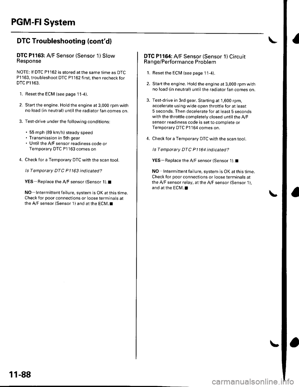
DTC Pl163: Ay'F Sensor (Sensor 1 ) SlowResponse
NOTE: lf DTC P1162 is stored at the same time as DTC
P1163. troubleshoot DTC P1162 first, then recheckfor
DTC P1163.
1. Reset the ECM (see page 1 1-4).
2. Start the engine. Hold the engine at 3,000 rpm with
no load (in neutral) until the radiator fan comes on.
3. Test-drive under the following conditions:
. 55 mph (89 km/h) steady speed' Transmission in sth gear' Until the Ay'F sensor readiness code or
Temporary DTC Pl163 comes on
4. Check for a Temporary DTC with the scan tool.
ls Temporary DTC P 1163 indicated?
YES Replace the Ay'F sensor (Sensor 1).I
NO Intermittent failu re, system is OK at this time.
Check for poor connections or loose terminals at
the A'lF sensor (Sensor 1 ) and at the ECM. t
11-88
DTC Pl164: A,/F Sensor (Sensor 1) Circuit
Range/Performance Problem
1. Resetthe ECI\4 (see page 1t-4).
2. Start the engine. Holdtheengineat3,000 rpmwith
no load (in neutral) until the radiator fan comes on,
3. Test-drive in 3rd gear. Starting at 1,600 rpm,
accelerate using wide open throttle for at least
5 seconds. Then decelerate for at least 5 seconds
with the throttle completely closed until the A,/F
sensor readiness code is set to complete or
Temporary DTC P1 164 comes on.
4. Check for a Temporary DTC with the scan tool.
ls Temporary DTC P1164 indicated?
YES- Replace the A,,/F sensor (Sensor 1). I
NO Intermittent failure, system is OK at this time.
Check for poor connections or loose terminals at
the Ay'F sensor relay, at the Ay'F sensor (Sensor 1),
and at the EcM.l
Page 297 of 1139

PGM-FI System
DTC Troubleshooting (cont'dl
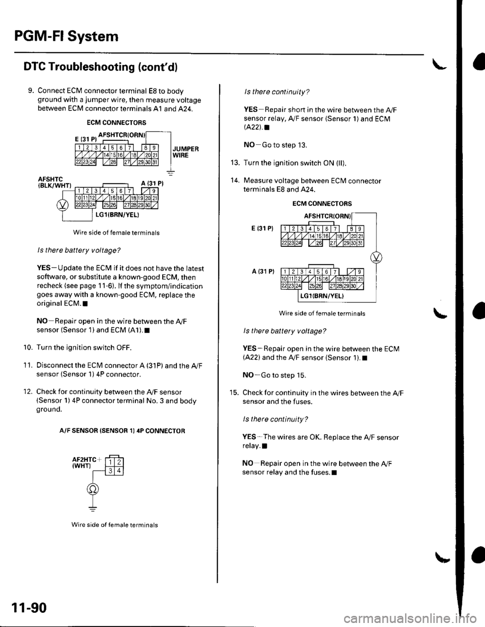
9. Connect ECM connector terminal EStobodyground with a jumper wire, then measure voltage
between ECM connector terminals A1 and 424.
ECM CONNECTORS
Wire side of female terminals
ls there battery voltage?
YES- Update the ECM if it does not have the latest
soflware, or substitute a known-good ECM, then
recheck (see page 1 1-6). lf the symptom/indication
goes away with a known-good ECM, replace the
original ECM. t
NO Repair open in the wire between the Ay'F
sensor (Sensor 1) and ECM (A1). t
Turn the ignition switch OFF.
Disconnecl the ECfM connector A (31P) and the Ay'F
sensor (Sensor 1) 4P connector.
Check for continuity between the Ay'F sensor(Sensor 1) 4P connector terminal No. 3 and bodyground.
A/F SENSOR (SENSOR 1) 4P CONNECTOR
10.
11.
12.
11-90
Wire side ot Iemale terminals
t5.
14.
ls there continuity?
YES Repair short in the wire between the A|/F
sensor relay, A,/F sensor {Sensor 1) and ECM
lA22J.a
NO Go to step 13.
Turn the ignition switch ON (ll).
Measure voltage between ECM connector
terminals E8 and A24.
ECM CONNECTORS
E {31 P)
a {31 P)
Wire side of female terminals
ls there battety voltage?
YES-Repair open in the wire between the ECM(A22) and the IVF sensor (Sensor 1). I
NO-Go to step 15.
Check for continuity in the wires between the Ay'F
sensor and the fuses.
ls there continuity?
YES-The wires are OK. Replace the A,/F sensor
relay.l
NO Repair open in the wire between the Ay'F
sensor relay and the fuses.l
Page 299 of 1139

PGM-FI System
I
a
DTC Troubleshooting (cont'dl
DTC Pl297: ELD Circuit Low Voltage
1. Reset the ECM {see page 11-4).
2. Start the engine.
3. Turn on the headlights.
ls DTC P1297 indicated?
YES Go to step 4.
NO Intermittent failure, system is OK at this time.
Check for poor connections or loose terminals at
the ELD and at the ECM.I
4. Turn the ignition switch and the headlights OFF.
5. Disconnectthe ELD 3P connector.
6. Turn the ignition switch ON {ll).
7. Measure voltage between body ground and ELD 3P
connector terminal No. 3.
ELO 3P CONNECTOB
{GRN/REDI
Wire side of female terminals
ls there about 5 V?
YES Replace the ELD. t
NO-Go to step 8.
Z3ELD
11-92
8. Turn the ignition switch OFF.
9. Disconnect ECM connector E {31P).
10. Check for continuity between body ground and
ECM connector terminal E15.
ECM CONNECTOR E 131PI
I l2l3456178I
totd/ 12021,2 2al2/tA31
ELD(GRN/RED}7\'
Wire side of female terminals
ls there continuity?
YES-Repair short in the wire between the ECM(E 15) and the ELD. r
NO- U pdate the ECM if it does not have the latest
software, or substitute a known-good ECM, then
recheck (see page 1 1-6). lf the symptom/indication
goes away with a known-good ECM, replace the
original ECM.I