2002 HONDA CIVIC turn signal bulb
[x] Cancel search: turn signal bulbPage 25 of 1139

t
v
2-13
o
o
a
ItemMeasurementOualilicationSpecitication
ELECTRICAL
RATINGS
Battery12V 36 AH/5 hours
Sta rter12 V-.1.1 kW, 1.2 kW
Alternator12V 95A,90A
FusesUnder-hood fuse80 A, 60 A, 50 A, 40 A, 30 A, 20 A, 15 A, 10 A, 7.5 A
Under'dash Iuse30 4,20 a, 15 A, 10 A,7.5 A
Light bulbsHeadlight high
beam
'12 v.' 60 w
Headlight low
beam
12V 55W
Frontturn signal
liqhts
12V 21W
Front parlinq lights12V 5W
Bear turn signal
lights
12V " 21W
FronVrear side
marker lights
12V 5W
Brale/taillighls12V 21/5W
High moLrnt brake
light
12V 5W
Back up lights12V 21W
License plate light12V 5W
Ceiling light'12 v'.8 w
Cargo area light12V 5W
Spotlights12V 5W
Gauge lights
Indicator lightsLED
Side turn signal
light
12V 5W
Page 219 of 1139

Fuel and Emissions Systems
System Descriptions
Electronic Control System
The functions of the fuel and emlssion control systems are managed by the engine control module (ECM).
Fail-safe Function
When an abnormality occurs in the signal from a sensor, the ECI\4 ignores that signal and assumes a pre-programmed
value for that sensor that allows the enqine to continue to run.
Back-up Function
When an abnormality occurs in the ECM, the injectors are controlled by a back-up circuit independent of the system to
permit minimal driving.
Self-diagnosis
When an abnormality occurs in the signal from a sensor, the ECM supplies ground for the malfunction indicator lamp
{MlL) and stores the diagnostic trouble code {DTC) in erasable memory. When the ignition is first turned on, the EClvl
supplies ground to the l\4lL for 15 to 20 seconds to check the M lL bulb condition.
Two Driving Cycle Detection Method
To prevent false indications, the "two driving cycle detection method" is used for some self-diagnostic functions.
When an abnormality occurs, the ECM stores it in its memory. When the same abnormality recurs afterthe ignition
switch is turned OFF and ON (ll) again, the ECM turns on the MlL.
\
11-12
\.
\{
Page 509 of 1139

EPS Components
aGeneral Troubleshooting Information
EPS Indicator
Under normal conditions, the EPS indicator comes on when
the ignitlon switch is turned to the ON (ll) position, then goes
off after the engine is started. This indicates that the bulb and
its circuit are operating correctly.
lf there is any trouble in the system after the engine is started,
the EPS indicator will stay on, and the power assist is turned
off.
When EPS indicator light comes on, the control unit
memorizes the DTC. In this case, the control unit will not
activate the EPS system after the engine starts again, but it
keeps the EPS indicator on.
When DTC 12, 16, 17, 18 or 67 is stored in the control unit, the
EPS indicator will stay on until the DTC is erased. When a
problem is detected and the EPS indicator comes on, there are
cases when the indicator stays on untilthe ignition switch is
turned 0FF, and cases when the indicator goes off
automatically when the system returns to normal. Even though
the system is operating normally, the EPS indicator will come
on under the following conditions:
Condition '1:
. The vehicle was traveling at least 12.4 mph (20 km/h), then. A rapid change in vehicle speed was detected, then. The vehicle (or the vehicle speed sensor signal) stopped for
at least 5 seconds. The engine speed was still 'l,640rpmorhigherforatleastS
seconds
Condition 2:
After the vehicle (or the vehicle speed sensor signal) has
stopped for at least 10 seconds, yet the engine speed was still
1,640 rpm or higherfor at least 20 seconds.
Condition 3:
When the engine speed is 280 rpm or less, and the vehicle is traveling at
a speed of 6,2 mph (10 km/h) or more for 3 seconds.
To determine the actual cause ofthe problem, question the
customer about the conditions during which the problem
occured, taking the above conditions into consideration.
Diagnostic Trouble Code (DTCI
. lf the CPU cannot be activated, or itfails,the EPS indicator
comes on, but the DTC is not memorized.. The memory can hold any number of DTCS. However, when
the same DTC is detected more than once, the most recent
DTC is written over the prior DTC, therefore only one
occurrence is memorized.. The DTCS are indicated repeatedly untilthe ignition switch is
turned OFF.. lf the DTC is not memorized,the EPS indicator blinks.
. The DTCS are memorized in the EEPRO| (non-volatile
memory) therefore the memorized DTCS cannot be erased
by disconnecting the battery. Perform the specified
procedures to clear DTCS.
Self-diagnosis
Self-diagnosis can be classified into two categories:.Initial diagnosis: performed right after the engine
starts and until the EPS indicator goes off.. Regular diagnosis: performed right after the initial
diagnosis until the ignition switch is turned OFF.
The EPS control unit performs the following functions
when a problem is detected by self-diagnosis;
'1. Turns on the EPS indicator.
2. Memorizes the DTC.
3. Stops power assist and manual steering operation
begrns.
NOTE:. When DTC 23 (a problem with the circuit for
engine speed signal) is detected, the power
assist will return to normal when the vehicle
speed is 0.62 mph (1 km/h) or above.. Fot DfCs 22,23, 64, or 66 the EPS indicator goes
off automatically when the system relurns to
normal. For all other codes, the EPS indicator
goes off when the system is OK after the ignition
switch is turned from OFF to ON (ll).
Restriction on Power Assist Operation
Repeated extreme steering force. such as turning the
steering wheel continuously back-and-forth with the
vehicle stopped, causes an increase of power
consumption in the EPS motor. The increase of electric
current causes the motor to heat up. Because this heat
adversely affects the system, the control unit monitors
the electric current of the motor.
When the control unit detects heat build-up in the motor,
it reduces the electric current to the motor gradually to
protect the system, and it restricts the power assist
operation. The EPS indicator does not come on during
this function.
When steering torque is not applied to the steering
wheel, or when the ignition is turned off, and the motor
cools, the control unit will restore the power assist
gradually until it's fully restored (after approximately 15
minutes maximum).
17-18
Page 831 of 1139

\Body Electrical
Body ElectricalSpecialToolsGeneral Troubleshooting tntorrnaiion.'......
Relay and Control Unit Locations .....
Connectors and Harnesses
Fuse/Relay Boxes ...............................
Power Distribution .............................
Ground Distribution ...........................
Under-dash Fuse/Relay Box ..............
Battery ..............
Relays ................
*lgnition Switch ..............
*Gauges
Component Location Index .......................Self-diagnostic Procedure ..........................Circuit DiagramGauge Bulb Replacement ..........................Gauge Assembly ReplacementCoolant Temperature
Gauge Troubleshooting .... ....................Vehicle Speed Signal CircuitTroubleshootingVSS Replacement
Exterior LightsComponent Location Index .......................Circuit DiagramDaytime Running Lights ControiUnit Input Test (Canada) ........................Headlight Ad,ustment .................. .. .....Headlighr Replacement ..............................Combination Light SwitchTest/ReplacementBulb ReplacementTaillight Replacement ..........................High Mount Brake Light Replacement ......License Plate Light Replacement ..............Side Marker Light Replacement ................Brake Pedal Position Switch Test ..............Side Turn Signal Light Replacement ........
Turn Signal/HazardFlasher SystemComponent Location Index .......................Circuit DiagramTurn Signal/Hazard Relay lnputTest ........Hazard Warning Switch Test
22,3
22-7
22-13
22-44
22-46
22-4A
22-49
22-50
22-51
22-53
22-5422-5622-5422 6322-64
22-64
22-6522 61
22-6822--71
22-7 622-7422-79
22-AO22-4122-8222-4222-4322-4322-4422-84
22-8�522 A622-8722-88
22-10422-105
22-10622-107
Entry Lights control systemComponent Location Index ....................... 22-89Circuit Diagram ......... 22 90lgnition Key Switch Test .....................,...... 22-9'llgnition Key Light Test ............................... 22-91Control Unit Input Test ..........,.................... 22 92
Interior LightsComponent Location Index ....................... 22-94Circuit Diagram ......... 22-95Ceiling LighVSpotlightsTesVReplacement ................................... 22-96Rear Ceiling Light TesVReplacem ent ........ 22-96Cargo Area Light Test/Replacem ent ......... 22-97Hatch Latch Switch Test ..,..,....................... 22-97
*Audio SystemComponent Location Index ....................... 22-98Circuit Diagram ......... 22,99Audio Unit Removal/lnstallation ............... 22-1OOAudio Unit Connector Replacement ......... 22-101Speaker Replacement ................................ 22-102Roof Antenna Rep1acement ....................-.. 22-103
Rear Window DefoggerComponent Location Index ...........Circuit Diasram .. ....... .. ..... ....... ...:::::.::.::.Function TestDefogger Wire Repair .................................Noise Condenser CapacityTest ................
MoonroofComponent Location Index ....................... 22-1OBCircuit Diagram ......... 22-109Moonroof Control Unit Input Test ............. 22-'l10Switch TesVReplacement ........,.....,........... 22-1 12Motor Test ................. 22-112Limit Swilch Test ...... 22-'l'13Auto-stop Switch Test ................................ 22-1 13
Power MirrorsComponent Location Index ....................... 22-114Circuit Diagram ......... 22-115Function Test ............. 22-116Power Mirror Switch Test .......................... 22-ll7Power Mirror Actuator Test ....................... 22-117Power Mirror Actuator Replacement ........ 22-11A
* HornsComponent Location Index ....................... 22-120Circuit Diagram ......... 22-121Horn TesVReplacement ...........................-. 22-122Horn Switch Test .,.... 22-122
\
Page 894 of 1139

Gauge Bulb Replacement
CRUISEHIGH BEAM INOICATOR LIGHT {1.4 W)ITOR LIGHT {I.4 W)LEFT TURN SIGNAL INDICATOR LIGHT l1.il wl
GAUG€ LIGHT {1.4 WI
IMMOBILIZEN INDICATORLTGHT {1.4 Wl
GAUGE LIGHT {1.4 W}
RIGHTTURN SIGNAL INDICATOR LIGHT {1.4 WI
22-63
Page 899 of 1139

Exterior Lights
Gomponent Location Index
UNDER.HOODFUSE/RELAY BOX
\/
HEADLIGHTSReplacement, page 22 79Adjustment. page 22-78Eulb Replacement, page 22-81
HEADLIGHT RELAY 1Test, page 22-51
HEADLIGHT RELAY 2Test, page 22-5'l
0/
FRONT SIDE MARKER LIGHTBulb Replacement, page 22 83
BRAKE PEDAL POSITIONswtTcHTest, page 22-84Adjustment, page l9'6
SIDE TURN SIGNAL LIGHTReplacement, page 22-84
FRONT TURN SIGNALLIGHTBulb Beplacement, page 22 81
PARKING LIGHTBulb Replacement, page 22-81
22-68
Page 912 of 1139

Bulb Replacement
Headlight:
1. Disconnect the 3P connector (A) from the headlight.
Headlight {high/low): 60/55 W
f-rI-'-+lA- )/
Remove the rubber cover (B).
Pull the retaining spring (C) away from the bulb (D),
then remove the bulb.
Install a new bulb in the reverse order of removal.
Make sure the notches in the bulb align with the
tabs ln the headlight.
2.
Front Turn Signal Light:
Parking Light:
1. Remove the inner fender (see page 20-102).
2. Disconnectthe connectors (A) from the lights.
21W
5W
4.
Front turn signal light:
Parking light:
Turn the bulb sockets (B) 45'counterclockwise to
remove them from the headlight housing.
Installthe new bulb(s) in the reverse order of
removat.
22-81
Page 913 of 1139

Exterior Lights
1.
2.
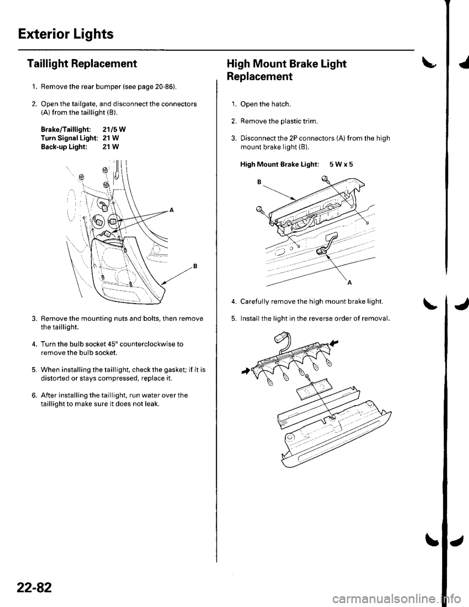
Taillight Replacement
Remove the rear bumper (see page 20-86).
Open the tailgate, and disconnect the connectors(A) from the taillight (B).
Brako/Taillight; 2115W
Turn Signal Light: 21 W
Back-up Light: 21W
Remove the mounting nuts and bolts, then remove
the taillight.
Turn the bulb socket 45' counterclockwise to
remove the bulb socket.
When installing the taillight. check the gasket; if it is
distorted or stays compressed, replace it.
After installing the taillight. run water over the
taillight to make sure it does not leak.
=\
ili--- _ \
rB , \.
---'a t
\
22-82
High Mount Brake Light
Replacement
1. Open the hatch.
2. Remove the plastic trim.
3. Disconnectthe 2P connectors (A)from the high
mount brake light (B).
High Mounl Brake Light: 5 W x 5
Carefully remove the high mount brake light.
lnstall the light in the reverse order of removal.5.
'