2002 HONDA CIVIC PGM-FI System
[x] Cancel search: PGM-FI SystemPage 269 of 1139

PGM-FI System
(
(
DTC Troubleshooting (cont'd)
DTC P0123: TP Sensor Circuit High Voltage
1. Turn the ignition switch oN (ll)
2. Check the throttle position with the scan tool.
ls there about 10% or 0.5 V when the throttle is
fully closed and about 90% or 4.5 V when the
throttle is f ully opened?
YES lntermittent failure. system is OK at this time.
Check for poor connections or loose terminals at
the TP sensor and at the ECM, I
NO Go to step 3.
3. Turn the ignition switch OFF.
4. Disconnect the TP sensor 3P connector.
5. Turn the ignition switch ON (ll).
6. At the wire harness side, measure voltage between
the TP sensor 3P connector terminals No. 1 and
No.3.
TP SENSOR 3P CONNECTOR
W;re side of female terminals
ls thete about 5 V?
YES-Replace the throttle body (the TP sensor is
not available separately). I
NO Go to step 7.
11-62
7. Measure voltage between ECM connector
terminals A10 and A20.
ECM CONNECTOR A 131PI
Wire side of female terminals
Is there about 5 V?
YES- Repair open in the wire between the ECM(A10) and the TP sensor. t
NO Update the ECM if it does not have the latest
soflware, or substitute a known-good ECM, then
recheck (see page 11-6). lf the symptom/indicationgoes away with a known-good ECM, replace the
original ECM.I
Page 271 of 1139

PGM-FI System
aDTG Troubleshootang (cont'dl
DTC P0128: Cooling System Malfunction
NOTE; lf the DTCS listed below are stored at the same
time as DTC P0128. troubleshoot those DTCS first, thenrecheck for P0128.
P0107, P0108, P1128, P1129: N4anifold absolutepressure (MAP) sensor
P] I06, P1 107, P1 108: Barometric pressure (BARO)
sensor
P1259: VTEC system
P01 16, P01 17, P01 18: Engine coolant temperature (ECT)
sensor
P01 12, P01 13: Intake air temperature (lAT) sensor
P0500: Vehicle speed sensor {VSS)P0335, P0336: Crankshaft position (CKP) sensor
P0300: Random misfire
P0301, P0302, P0303, P0304: No. 1, No. 2, No.3 or No.4
cylinder misfire
P0505: ldle control system malfunction
P1519: ldle air control (lAC)valve
DTC P0128 can occasionally set when the hood is
opened while the engine is running.
1. Check the engine coolant level
Is the engine coolant level low?
VES Refill the engine coolant. lf necessary, repair
the coolant leakage.l
NO Go to step 2.
2. Turn the ignition switch ON (ll), and make sure the
A,/C is off.
11-64
\
3. Check the radiator fan.
Does the tadiator fan keep running?
YES Checkthe rad iato r fan circuit (see page 10-
14), the radiator fan switch circuit (Short) (see page
10-'16), and the radiator fan switch (see page 10-17).
Also, inspect the ECT and IAT circuits and terminal
connections. lf the circuits, the switch, and the
connections are OK, update the ECI\4 if it does not
have the latest software. or substitute a known-good ECM, then recheck (see page 1 1-6). lf the
symptom/indication goes away with a known-good
ECM, replace the original ECM.I
NO Replace the thermostat (see page 10-8).1
Page 273 of 1139

PGM-FISystem
aDTC Troubleshooting (cont'dl
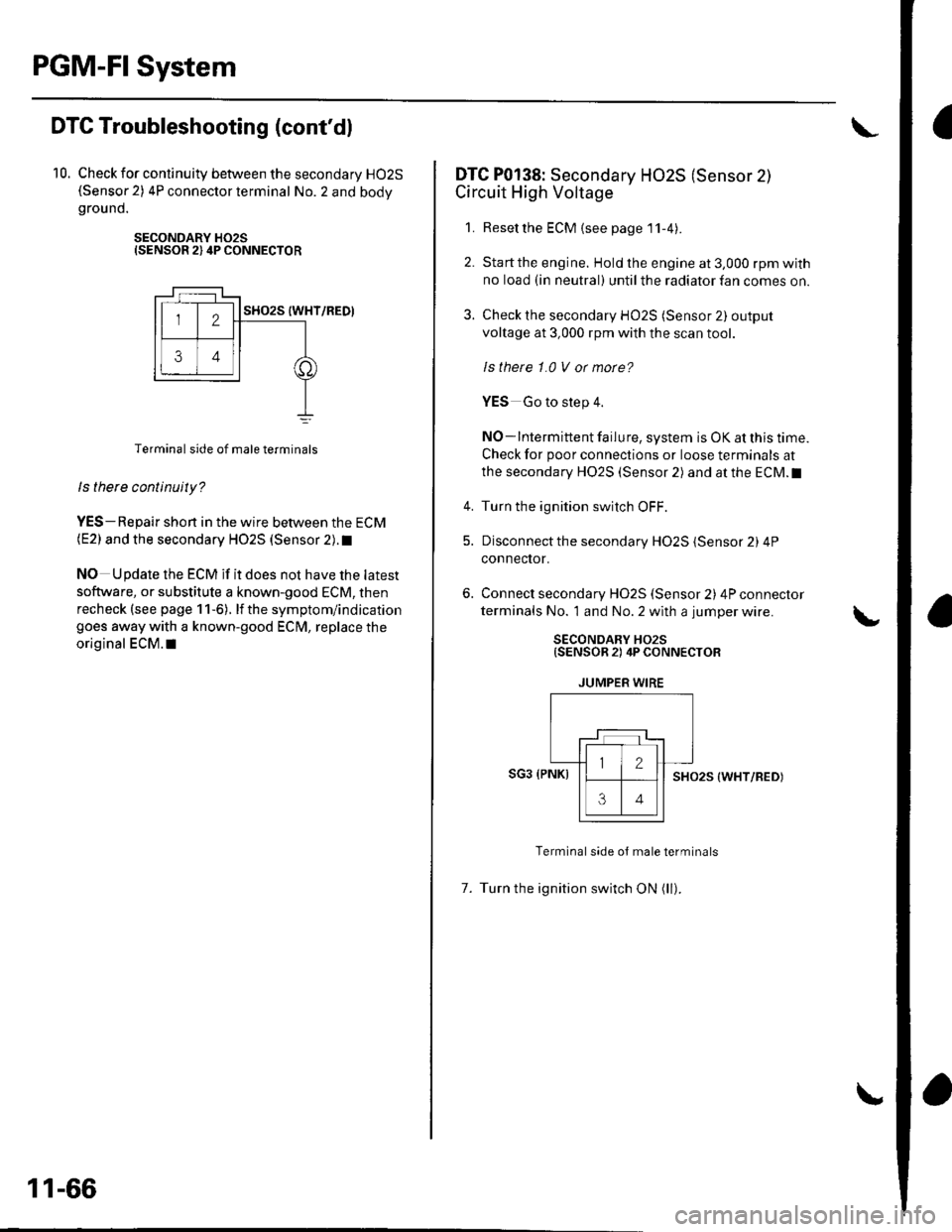
10. Check for continuity between the secondary HO2S(Sensor 2) 4P connector terminal No. 2 and bodygrou nd.
SECONDARY H02SISENSOR 2) 4P CONNECTOR
Terminal side of male terminals
ls there continuity?
YES-Repair shon in the wire between the ECM(E2) and the secondary HO2S (Sensor 2). t
NO Update the ECM if it does not have the latest
software, or substitute a known-good ECM, then
recheck (see page 1 1-6). lf the symptom/indication
goes away with a known-good ECM, replace the
original ECM.I|
11-66
DTC P0138: Secondary HO2S (Sensor 2)
Circuit High Voltage
1. Resetthe ECM {see page'11-4).
2. Startthe engine. Hold the engine at 3,000 rpm with
no load (in neutral) until the radiator fan comes on.
3. Check the secondary HO2S (Sensor 2) output
voltage at 3,000 rpm with the scan tool.
ls thete 1.0 V or morc?
YES Go to step 4.
NO-lntermittent failure, system is OK at this time.
Check for poor connections or loose terminals at
the secondary HO2S (Sensor 2) and at the ECM.I
4. Turn the ignition switch OFF.
5. Disconnect the secondary HO2S (Sensor 2) 4P
connector.
Connect secondary H02S (Sensor 2) 4P connector
terminals No. 1 and No. 2 with a jumper wire.
SECONDARY HO2S{SENSOR 2) 4P CONNECTOR
JUMPER WIRE
SG3 (PNKISHO25 (WHT/RED)
Terminal side oJ male terminals
7. Turn the ignition switch ON (ll).
Page 275 of 1139

PGM-FISystem
3.
DTC Troubleshooting (cont'dl
DTC P0141: Secondary HO2S (Sensor 2l
Heater Circuit Malfunction
1. Reset the ECM (see page 1 l-4)
2. Start the engine.
ls DTC P0141 indicated?
YES-Go to step 3.
NO-lntermittent failure, system is OK at this time.
Check for poor connections or loose terminals at
the secondary HO2S (Sensor 2) and at the ECM.I
Turn the ignition switch OFF.
Disconnect the secondary H02S (Sensor 2) 4P
connecror.
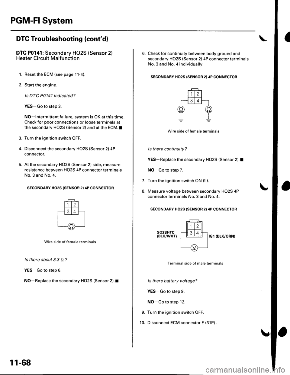
At the secondary HO2S (Sensor 2) side, measure
resistance between H02S 4P connector terminals
No.3 and No. 4.
SECONDARY HO2S (SENSOR 21 4P CONNECTOR
Wire side ol lemale terminals
ls there about 3.3 Q ?
YES Go to step 6.
NO- Replace the secondary HO2S (Sensor 2). t
5.
11-68
6. Check for continuity between body ground and
secondary H02S (Sensor 2) 4P connector terminals
No.3 and No. 4 individually.
SECONDARY HO2S {SENSOR 21 4P CONNECTOR
Wire side of female terminals
ls there continuity?
YES- Replace the secondary HO2S (Sensor 2).1
NO-Go to step 7.
Turn the ignition switch ON (ll).
Measure voltage between secondary H02S 4P
connector terminals No. 3 and No. 4,
SECONDARY HO2S (SENSOR 2l ilP CONNECTOR
t
7.
8.
9.
10.
s02sHTc{BLK/WHTIIG1 (BLK/ORN}
Terminal side of male terminals
ls there battery voltage?
YES Go to step 9.
NO Go to step 12.
Turn the ignition switch OFF.
Disconnect ECM connector E {31P)
Page 277 of 1139

PGM-FI System
DTC Troubleshooting (cont'dl
DTC P0171: Fuel System Too Lean
DTC P0172: Fuel System Too Rich
NOTE: lf some of the DTCS listed below are stored at
the same time as DfC PO17'l and/ot PO172,
troubleshoot those DTCS first, then recheck for P0171
andlot P0112.
P0107, P0108. P1 128. P1 129: Manifold absolute
pressure (MAP) sensor
P1 162. P1 166, P 1 167: 4,,/F sensor (Sensor 1 ) heater
P0137, P0138: Secondary HO2S (Sensor 2)
P014'l: Secondary HO2S (Sensor 2) heater
P1259: VTEC system
1. Check the fuel pressure (see page 11-'145).
ls luel pressure OK?
YES Go to step 2.
NO Check these items:
. lf the pressure is too high, replace the fuel
pressure regulator (see page 11-152).1. lf the pressure istoo low.checkthefuel pump,
the fuel feed pipe, the fuel filter, and replace the
fuel pressure regulator (see page 11-152).I
2. Start the engine. Hold the engine at 3,000 rpm with
no load (in neutral) until the radiator fan comes on.
11-70
3. Turn the ignition switch OFF.
4. With a vacuum pump, apply vacuum to the
evaporative emission (EVAP) canister purge valve
(A) from the evaporative emission (EVAP) canister
side.
' A973AX-041-XXXXX
Does it hold vacuum?
YES-Check the engine valve clearances and adjust
if necessary, lf the valve clearances are OK, replace
the injectors (see page 1 1-1 1 1).1
NO-Replace the EVAP canister purge valve.l
Page 279 of 1139

PGM-FI System
IDTC Troubleshooting (cont'dl
DTC P0301: No. 1 Cylinder Misfire
DTC P0302: No. 2 Cylinder Misfire
DTC P0303: No. 3 Cylinder Misfire
DTC P0304: No. 4 Cylinder Misfire
1. After checking and recording the freeze data, reset
the ECM (see page 1 1-4). lf there is no freeze data of
the misfire, just clear the DTC.
2. Start the engine, and listen for a clicking sound
from the injector at the problem cylinder.
Does the injector click?
YES-Go to step 3.
NO-Go to step 30.
3. Turn the ignition switch OFF.
4. Exchange the ignition coil from the problem
cylinder with one from another cylinder,
5. Test-drive the vehicle for several minutes in the
range of the freeze data or under va rious
conditions if there was no freeze data.
6. Check for a DTC or a Temporary DTC with the scan
root.
ls DTC or Tempotaty DTC P0301, P0302, P0303
or P0304 ind icated?
YES Go to step 7.
NO Intermittent misfire due to poor contact at the
ignition coil connectors {no misfire at this time).
Make sure the coil connections are secure.l
11-72
8.
9.
1.
11.
Determine which cylinder(s) had the misfire.
Does the misf ire occur in the cylinder where the
ignition coil was exchanged?
YES Replace the faulty ignition coil.!
NO-Go to step 8.
Turn the ignition switch OFF.
Exchange the spark plug from the problem cylinder
with one from another cylinder.
Test-drive the vehicle for several minutes in the
range of the freeze data or under various
conditions if there was no freeze data.
Check for a DTC or Temporary DTC with the scan
Tool.
ls DTC ot Tempotary DTC P0301, P0302, P0303
or P0304 ind icated?
YES Go to step 12.
NO Intermittent misfire due to spark plug fouling,
etc. (no misfire at this time).1
Determine which cylinder(s) had the misfire.
Does the misl ire occur in the cylinder where the
spark plug was exchanged?
YES Replace the faulty spark plug.l
NO Go to step 13.
Turn the ignition switch OFF.
Exchange the lnjector from the problem cylinder
with one from another cylinder.
Let the engine idle for 2 minutes.
10.
14.
t5.
Page 281 of 1139

PGM-FI System
aDTC Troubleshooting (cont'dl
26. Check for continuity between body ground and
ECM connector terminal (see table).
ECM CONNECTOR A {31PI
PROB LE IVI
CYLINDER
DTCECM
TERMINAL
WIRE
COLOR
No. 1P0301430YEUGRN
No.2P0302A.29BLU/RED
No.3P0303428WHT/BLU
No,4P0304421BRN
ls there continuity?
YES Repair shon in the wire between the EClvl
and the ignition coil.l
NO-Go to step 27.
27. Connect ignition coil 3P con nector term inal No. 1to
body ground with a jumper wire (see table).
IGNITION COII 3PCONNECTOR
Wire s de of femaleterminals
PROBLEM
CYLINDER
DTCWIRE COLOR
No. 1P0301YEUGR N
No. 2P0302BLU/RED
No. 3P0303WHT/BLU
No. 4P0304BRN
11-74
28. Check for continuity between body ground and
ECM connector terminal (see table).
ECM CONNECTOR A {31P}
PROBLEM
CYLINDER
DTCECM
TERI\4INAL
WIRE
COLOR
No. 1P0301A30YEL/GRN
No. 2P0302429BLU/RED
No. 3P0303A.28WHT/BLU
No. 4P0304A.21BRN
ls there continuity?
YES-Go to step 29.
NO Repair open in the wire between the ECM and
the ignition coil.l
29. Check the engine compression
ls the compression OK?
YES-Update the ECM if it does not have the latest
software, or substitute a known-good ECM, then
recheck (see page 11-6). lf the symptom/indication
goes away with a known-good ECM, replace the
original ECI\4.I
NO- Repair the engine.l
Disconnect ECM connector B (24P).
Turn the ignition switch ON (ll).
30.
Page 283 of 1139
![HONDA CIVIC 2002 7.G Workshop Manual PGM-FI System
a
I
DTC Troubleshooting (contdl
45. Measure voltage between injector 2P connector
terminal No. 1 and body ground.
INJECTOR 2P CONNECTOR
tll-z]
,o, ,"=rrrr*, -lt-
oI
Wire side of female HONDA CIVIC 2002 7.G Workshop Manual PGM-FI System
a
I
DTC Troubleshooting (contdl
45. Measure voltage between injector 2P connector
terminal No. 1 and body ground.
INJECTOR 2P CONNECTOR
tll-z]
,o, ,"=rrrr*, -lt-
oI
Wire side of female](/manual-img/13/5744/w960_5744-282.png)
PGM-FI System
a
I
DTC Troubleshooting (cont'dl
45. Measure voltage between injector 2P connector
terminal No. 1 and body ground.
INJECTOR 2P CONNECTOR
tll-z]
,o, ,"=rrrr*, -lt-
oI
Wire side of female terminals
ls there battery voltage?
YES-Go to step 46.
NO-Repair open in the wire between the injector
and the PGM-Fl main relay l.l
Turn the ignition switch OFF.
Check for continuity between body ground and
ECM connector terminal (see table).
46.
47.
ECM CONNECTOR B {24P)
Wire side of female terminals
ls there continuity?
YES-Repair short in the wire between the ECM
and the ;njector.I
NO-Go to step 48.
PROBLEM
CYLINDER
DTCECM
TERMINAL
WIRE
COLOR
No. 1P030'1B5BRN
No.2P0302B4RED
No.3P0303B3BLU
No. 4P030482YEL
11-76
48. Connect injector 2P co nnector term inal No.2 to
body ground with a jumper wire {see table).
INJECTOR 2P CONNECTOR
Wire side of {emale terminals
49. Check for continuity between body ground and
ECM connector terminal (see table).
ECM CONNECTOR B I24P)
Wire side oJ temale terminals
ls therc continuity?
YES Replace the injector, then recheck.l
NO Repair open in the wire between the ECM and
the injector.I
tll-Z-l-]_r-l_rNJ
IJUMPER
IwrBE
PROBLEM
CYLINDER
DTCWIRE COLOR
No. 1P0301BRN
No.2P0302RED
No. 3P0303BLU
No. 4P0304YEL
PROBLEM
CYLINDER
DTCECM
TERMINAL
WIRE
COLOR
No. 1P0301B5BRN
No. 2P0302B4RED
No. 3P0303B3BLU
No. 4P030482YEL